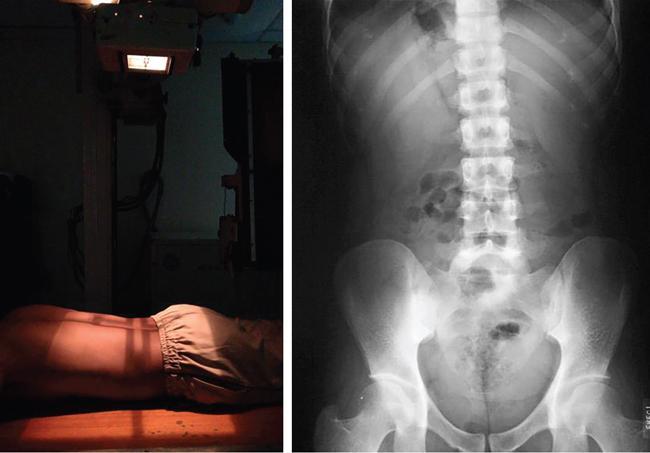
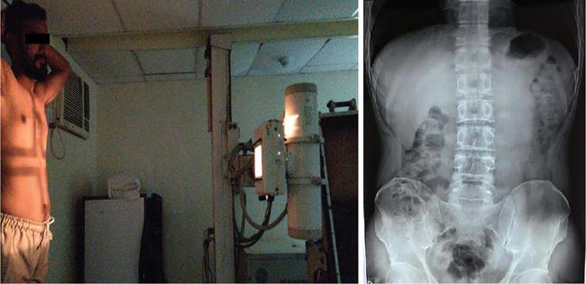
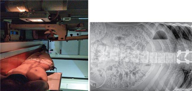
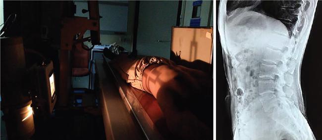
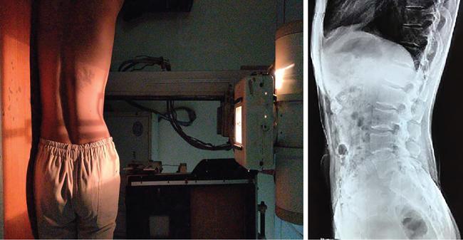
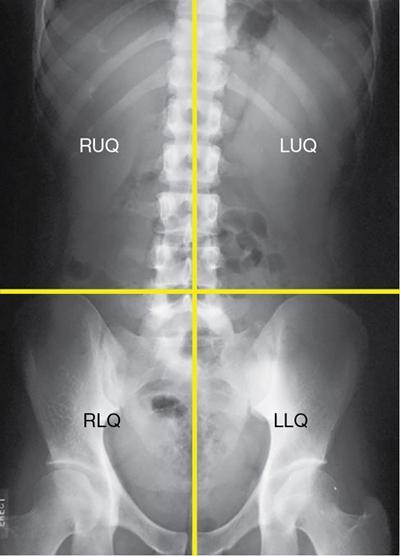
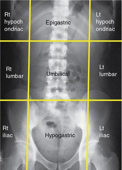
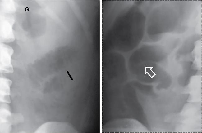
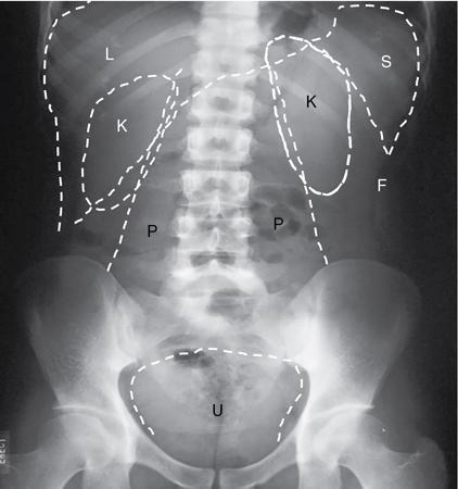
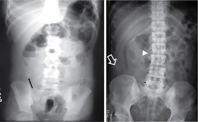
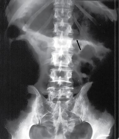
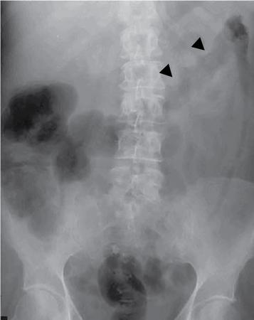
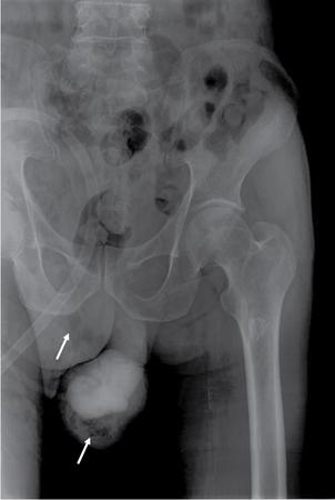
UNDERSTANDING THE ADULT ABDOMINAL RADIOGRAPH: TECHNIQUES AND INTERPRETATION Tanvi Modi Radiography of the abdomen is a common practice for the evaluation of abdominal organs. The anatomy and pathology of digestive, hepatobiliary and genitourinary systems can be assessed using radiographs, either as a stand-alone practice or as a primary imaging modality followed by contrast studies, ultrasound or cross-sectional imaging. In addition, abnormalities of the musculoskeletal or integumentary system can also be deduced on the basis of abdominal radiographs. This chapter intends to give an overview on the techniques and positioning in abdominal radiography as well as interpretation of normal and abnormal features. While superior imaging modalities such as ultrasound, computed tomography (CT), magnetic resonance imaging, capsule endoscopy and the likes have taken over abdominal imaging by and large, radiography still holds a pivotal role in certain situations and conditions, such as: The standard abdominal radiograph is taken in supine position and anteroposterior projection. This is also popularly known as the KUB (kidneys-ureters-bladder) radiograph. Previously, supine as well as erect radiographs were performed in all patients; however, this is not commonly done due to high-radiation dose. For all indications of abdominal radiography, including acute abdomen, supine radiographs are sufficient in terms of radiographic diagnosis, with the exception of perforation for which an erect chest or lateral decubitus radiograph can be performed if there is clinical suspicion. Patient should lie supine on the imaging table with median sagittal plane at right angles to the table and coincident with the midline of the table (Fig. 7.1.1.1). The body is divided into equal right and left halves by the median sagittal which passes through the sagittal suture of the skull. Pelvis should be adjusted so that the anterior superior iliac spines are equidistant from the table top. Gonadal shields, in the case of male patients, should be placed with the upper edge of the shield at the level of pubic symphysis. Although rarely used for female patients, these should be positioned between the anterior superior iliac spines and the pubic symphysis. The centre point of the image receptor should be approximately located at a point 1 cm below the line joining the iliac crests. The X-ray beam should be in a vertical direction, perpendicular to the table top and image receptor at the centre point. Collimation should be such that the soft tissue and subcutaneous region along lateral aspects of the abdominal cavity should be covered within the image. Also, the superior extent involving diaphragm and inferior extent involving the inferior pubic rami is important to look for any lower chest pathologies or any inguinal hernia. 35 × 43 cm (14 × 17 inches) in portrait orientation. On an average, abdominal radiograph exposes a patient to a dose of approximately 1.5 mSv, which is equivalent to 75 chest radiographs or 1/6th dose of a standard CT of the abdomen. The entrance skin dose is approximated to be 4 mGy. At such an effective dose, the additional lifetime risk of fatal cancer is 1 in 30,000. The exposure time is kept short. Patient is asked to exhale completely and hold their breath, with exposure taken at this point of full expiration to ensure imaging of abdominal organs in their natural positions. Modifications of this technique can be made depending on patient habitus and clinical condition. Kilovoltage peak (kVp) should be set to allow adequate visualization of abdominal soft tissue structures as well as semiopaque renal and biliary calculi. Average kVp is set at 70–85 kV. 102 cm (40 inches) Grids are commonly used to reduce scatter radiation. Placement of side marker on the image receptor at the time of radiographic exposure is essential. Bowel pattern depiction should be such that there is minimal lack of sharpness. Standard guidelines for abdominal radiography dictate that the radiograph should extend from the diaphragm up to the level of inferior pubic rami and must include the lateral abdominal wall musculature. The abdomen is divided into four quadrants on the basis of two perpendicular lines (Fig. 7.1.1.7). The vertical line passes through the mid sagittal plane and crosses the umbilicus and symphysis pubis. The horizontal line is a transverse line across the umbilicus at 90 degrees to the vertical line and is situated at the level of L4–L5 intervertebral disc. The quadrants are as follows: Another division system is dividing the abdominopelvic cavity into nine regions using two vertical and two horizontal planes (Fig. 7.1.1.8). The vertical planes, also known as the right and left lateral planes, are parallel to the midsagittal plane between midline and anterosuperior iliac spines on either side. Of the two horizontal planes, the upper transpyloric plane is at the level of lower border of L1 and the lower transtubercular plane is at the level of L5. The nine regions are: On a standard radiograph, the exposure should be such that the stomach, bowel loops, outlines of liver, spleen, kidneys, psoas muscles should be well identified. Also, lumbar transverse processes should be seen. Arch of the pubic symphysis should be visible to evaluate bladder region. A well-centred film without rotation will demonstrate bilaterally symmetrical lower ribs, iliac wings, ischial spines and obturator foramina. Different structures seen on an abdominal radiograph can be classified into five basic densities: Identification of different structures depends on the relative degree of contrast between their densities. The demarcation is clearer in chest and is diminished in abdomen due to relative similar soft tissue density of various structures. On a normal radiograph, relatively large amounts of gas in stomach and colon with minimal small bowel gas can be seen. Further, colonic gas can vary from negligible to extensive, mimicking obstruction pattern; however, usually the gas is enough to delineate colonic haustral pattern. Faecal matter gives a mottled appearance to colonic gas. Short-air fluid levels on an erect radiograph may be seen even in normal cases. The normal appearance of small bowel loops on an abdominal radiograph follows the rule of threes: Stomach is seen in the left upper quadrant and is visualized when distended with air. It is commonly seen extending from T11 to L2 level. Common feature identifying the stomach is the fundal gas which is usually seen as an air fluid level within the gastric lumen. Small bowel loops are distributed to the centre of the abdominal cavity and large bowel loops are peripheral. Duodenum is predominantly situated in right upper quadrant. It extends to left upper quadrant in the region of duodenojejunal flexure. Jejunum occupies the left upper and lower quadrants and is easily identified due to the presence of thick, numerous, closely spaced valvulae conniventes (Fig. 7.1.1.9A). The ileum occupies both lower quadrants and extends into right upper quadrant. Ileum has few and less prominent valvulae as compared to jejunum (Fig. 7.1.1.9B). Ascending and descending colon are retroperitoneal and have relatively fixed positions along lateral aspect of the abdominal cavity on either side. Transverse and sigmoid colon, on the other hand, may have a variable position due to their mobility along mesocolon and redundant pattern. These can be identified with confidence on account of haustrations and faecal matter (Fig. 7.1.1.10). Haustrations are usually well seen in ascending and transverse colon and poorly delineated beyond splenic flexure. Caecum is in the right lower quadrant, though it may be mobile or pulled up. Rectal gas is usually seen in the midline at the level of pelvis and its presence rules out large bowel obstruction. All these positions may vary due to anatomical conditions such as malrotation or pathological conditions, for example volvulus. Liver, spleen and renal outlines cannot be completely traced with precision due to the overlap by bowel loops. On a frontal projection, the liver appears as a triangular structure occupying right and left hypochondrium and epigastric region. Occasionally, the right lobe may be seen extending lower than the right renal shadow. This is a normal variant known as Reidel’s lobe. Gall bladder is situated in the posterior and inferior region of the liver and any pathology of the gall bladder should be looked for in this region. On a lateral radiograph, the gall bladder is anterior to the midcoronal plane. This helps in distinguishing gall bladder calculi from renal calculi, which will be more posteriorly situated. Spleen is seen in left upper quadrant/left hypochondrium, flushed to left lower ribs and left hemidiaphragm. Pancreas is present in the epigastric region (right and left upper quadrants) and is usually not identified in the absence of a pathology. The kidneys are bean-shaped retroperitoneal organs which are seen on either side of the vertebral column and lateral to psoas muscles. Due to the presence of liver on the right side, this kidney is slightly lower in position as compared to its contralateral counterpart. The visualization of kidneys on radiographs is facilitated by the surrounding fatty capsule. Kidneys lie between T11–12 and L2 level, with left kidney 1 cm higher than the right. Psoas muscle shadow can be normally seen along lateral aspect of lumbar spine bilaterally and is mildly concave (Fig. 7.1.1.11). Abdominal wall muscles are not routinely assessed on radiography; however, inclusion of lateral abdominal wall (muscles as well as subcutaneous plane) is a must while performing radiography. The flank stripe or the properitoneal fat stripe is a fat density linear concavity seen along lateral abdominal wall (Fig. 7.1.1.11). It is bound by the paracolic gutters and air-filled ascending and descending colon. All the solid organs in the abdomen are identified due to the fat density outlining them. Distortion of these fat lines helps in identifying organomegaly or focal mass lesions. The dome of urinary bladder is outlined by fat, which aids in differentiating its density from other soft tissue structures of the pelvis. Not all calcifications seen on abdominal radiograph are abnormal. Some may depict age-related changes such as vascular calcifications involving abdominal aorta, pelvic vessels, splenic artery in the region of left upper quadrant. Within the pelvis, phleboliths may be seen and mistaken for urinary calculi. Assessment of lumbosacral spine, iliac bones and femoral heads can be made on the basis of plain radiography. Degenerative changes may be commonly seen. Lower ribs can also be evaluated for pathologies. Dilated small bowel loops with rounded soft tissue density in midline over umbilical region suggests obstruction secondary to umbilical hernia. Pneumoperitoneum must be looked for in all cases of acute abdomen. While erect chest and left lateral decubitus radiographs can detect even 1 mL of free air, there are multiple signs on supine radiograph to suggest this diagnosis, for example Rigler’s sign, falciform ligament sign, football sign (Figs. 7.1.1.24 and 7.1.1.25). Retroperitoneal perforation may demonstrate air outlining psoas muscles and retroperitoneal organs. Small amount of free air may persist in the abdominal cavity up to 3 weeks after surgery, although it usually resolves within a week. Clinical history is important in such cases. Air foci within the bowel wall may represent bowel ischaemia/strangulation. Linear gas patterns in right hypochondrium may be due to two causes, that is pneumobilia and pneumoporta. The former can be seen normally postbiliary surgery, sphincterotomy, ERCP or in the case of abnormal fistulous communication between bowel and biliary tree (Fig. 7.1.1.26A). Pneumoporta (Fig. 7.1.1.26B) is a red flag and warrants further investigation to look for conditions such as mesenteric ischaemia and toxic megacolon. Pneumobilia is more centrally located whereas air shadows in pneumoporta are seen reaching up to periphery of liver. Air foci over renal shadows (Fig. 7.1.1.27), gall bladder or pancreas, in the absence of recent procedural history, suggest fulminant infection and mandate urgent intervention. Central midline calcific foci between T9 and T12 vertebrae can be attributed to calcific pancreatitis (Fig. 7.1.1.28). In the left upper quadrant, areas of calcification seen involving a shrunken spleen may be seen in autosplenectomy. In right upper quadrant, calcified gall stones may be seen. These tend to be small, multiple, uniformly circumscribed and ring-like in appearance with central translucency (Fig. 7.1.1.29A). Mercedes Benz sign, a triradiate pattern of gas lucency, is associated with gallstones. In contrast, renal calculi are more commonly solitary, irregular, of homogenous density, conform to renal calyceal or pelvic outline (Fig. 7.1.1.29B) and are sometimes of staghorn configuration. On lateral view, the gall stones are more anteriorly located as compared to renal calculi, which may be partly superimposed on lumbar vertebrae. Ureteric calculi tend to overlap bony structures such as lumbar transverse processes (Fig. 7.1.1.29B) or sacroiliac joints. Extensive or patchy, curvilinear calcification of gall bladder wall is known as porcelain gall bladder which is often associated with malignant transformation. Calcification involving adrenal glands may be secondary to infection or haematoma, or a congenital condition known as Wolman’s disease where there is bilateral involvement. Discontinuous discrete midline tram track calcification in the abdomen may indicate atherosclerotic changes in abdominal aorta and branch vessels. However, when the calcification is in a globular pattern and seen below the level of L2 vertebra, aortic aneurysm should be suspected (Fig. 7.1.1.30). Appendicoliths, though not commonly seen, may sometimes be detected in right iliac region. Pelvic calcifications: vesical calculi, distal ureteric or vesicoureteric junction calculi, calcified fibroids, ovarian dermoid with tooth-like calcifications (Fig. 7.1.1.31) may be the cause of abdominal pain and should be diligently looked for. Vesical calculi are usually more large and central in location whereas calcification due to fibroids may be more lateral. Schistosomiasis is another cause of bladder wall calcification, as is calcification of bladder tumours. Phleboliths tend to be bilaterally symmetrical, with a lucent centre unlike ureteric calculi. While it is believed that phleboliths are located below the level of ischial spines and ureteric calculi above, this is not always true and should be confirmed with CT. Fluid may collect adjacent to properitoneal fat line, forming a linear soft tissue density separating the fat line from the ascending or descending colon. Hellmer’s sign demonstrates medial displacement of lateral edge of liver (hepatic angle), due to fluid collection or ascites. Gross ascites may appear as generalized abdominal haziness or diffuse increased density of pelvis. Abscesses can involve any solid organ and in such cases may be difficult to demonstrate on plain radiography alone. Enlargement of organ or faint gas densities within can be suggestive of the same. In the case of peritoneal abscess, mottled density due to air, fluid and necrotic contents point towards this diagnosis, especially in right iliac fossa in association with appendicitis. Retroperitoneal abscess, similar to any retroperitoneal mass, may cause displacement of retroperitoneal structures (Fig. 7.1.1.32). Subdiaphragmatic abscesses may show concomitant ipsilateral pleural effusion (Fig. 7.1.1.33). These should be differentiated from Chilaiditi syndrome. Fluid and soft tissue lesions present with the same density on radiographs. While it is difficult to characterize the lesion and organ of origin, clues for the same can be provided by organomegaly (Fig. 7.1.1.34), distortion of fat surrounding solid organs, displacement of bowel loops or solid organs. For example, a retroperitoneal lesion may cause anterior or inferior displacement of kidney, a pelvic mass may cause upward displacement of small bowel loops. Different densities such as fat or calcification may help in identifying organ of origin (e.g. fat and tooth densities seen in ovarian dermoid). Convexity of margins of psoas muscle on an abdominal radiograph can be due to haematoma, abscess or intramuscular tumour. Radiographs are performed for the initial diagnosis of foreign body in the abdomen including type, number of foreign bodies, location, size and shape (Fig. 7.1.1.35). Radiolucent foreign bodies such as wood, plastic, chicken bones will not be easily identified on radiography. Low kVp (65–70 kVp) can increase contrast and help identify these objects. In addition to an abdominal radiograph, chest radiography is also performed to exclude aspiration or oesophageal location of foreign body. Ingested or introduced foreign bodies may cause complications such as obstruction, perforation, fistula formation and sepsis. Hence, once their presence is confirmed, follow up radiography must be performed until they are eliminated. One must look for fractures/dislocation injuries involving the vertebrae or pelvic bones, especially after history of trauma. Lucent expansile lesions or sclerotic bony deposits which represent neoplasms, absent pedicle sign in cases of metastasis, metabolic bony changes such as rugger jersey appearance, Paget’s disease, arthropathies such as ankylosing spondylitis with bamboo spine appearance and sacroiliitis (Fig. 7.1.1.36) are some of the conditions which may be diagnosed based on an abdominal radiograph. Overlap of bowel loops over iliac blades may lead to a misdiagnosis of lucent lesions and should be evaluated with caution. Basal pneumonia may be the cause of acute abdominal pain and should be looked for in abdominal radiography. Similarly, pleural effusion, pericardial effusion, calcified pleural plaques, achalasia, interstitial fibrosis are few other findings that can be seen in lower chest on an abdominal radiograph. Basilar atelectasis can give a deceptive appearance of pneumoperitoneum (Fig. 7.1.1.37). Surgical clips, commonly in right hypochondrium after cholecystectomy, drainage tubes, ventriculoperitoneal shunts, femoral line catheters, IVC filters, stents (vascular, renal, biliary) (Fig. 7.1.1.38), stoma bags, contraceptive devices are some structures that may be seen in an abdominal radiograph. Correct knowledge of patient history and normal locations of these structures prevents misdiagnosis. Certain artefacts may be projected upon the radiograph due to surface structures such as trouser buttons, body piercing, sequins over clothing and should not be considered as a pathology. Multiple skin surface nodules in cases of neurofibromatosis, soft tissue focal swellings, such as abscesses, lipomas, haematomas, desmoid tumours and malignant lesions may be incidentally seen on radiography. These can be further evaluated using ultrasound or CT. Subcutaneous emphysema is another finding that may be seen in lower abdominal wall secondary to retroperitoneal perforation or diffusely along abdominal wall in the case of bowel perforation (Fig. 7.1.1.39). Foreign bodies such as bullets and pins may be seen lodged in abdominal wall. A systematic approach to abdominal radiographs is important for accurate diagnosis as follows: Despite the development of newer techniques for imaging of the abdomen, plain radiography still holds an important place in the initial assessment of acute abdomen. Positive and negative findings on an abdominal radiograph can direct further investigation. Ideal positioning, recognition of normal appearances and keen scrutiny for pathologies is a sine qua non for radiologists reading a plain film of the abdomen. OESOPHAGOGRAM Padma V. Badhe, Vikram Reddy, Sultan Moinuddin Shaukatali, Zillani Alam, Ravi Varma, Abhishek Bairy, Dasari Ravikiran, Revati Tekwani, Soniya Patankar, Megha Nair, Gautham Shankar Oesophagogram is the process of obtaining radiological images and simultaneous motion recording to evaluate function and disorders of pharynx, oesophagus and proximal stomach. Oesophagogram is usually done primarily to evaluate dysphagia. Some of the common indications are oesophageal motility disorders, strictures, gastro-oesophageal reflux disease (GERD) and suspected masses. It can also be used to detect uncommon anomalies like vascular rings/slings and aberrant anatomy. It also helps to evaluate further in cases where there is inability to pass upper GI scope. Double-contrast oesophagogram is mainly indicated in early mucosal disease like erosion, polyp, infection and tumours. If a motility disorder is suspected, dynamic technique (e.g. videofluoroscopy) is used for dysphagia or aspirations in cases of stroke, neuromuscular disorders, post head and neck surgery or radiation. Barium oesophagogram is contraindicated in suspected cases of perforation and tracheoesophageal fistula, aspiration, rarely if there is hypersensitivity to barium suspensions. It is also contraindicated in suspected oesophageal perforation where a water-soluble contrast agent is more suitable. However, ionic water-soluble contrast agent is better avoided in cases of aspiration or fistula with airway. The contrast examination of the pharynx is dangerous in cases of acute epiglottitis and must be ruled out on plain radiograph. An 80% w/v barium suspension is used in full column views. However, 200%–250% w/v barium suspensions is usually required for mucosal relief films. The barium sulphate mixture is fed to the patient either by spoon, by glass, or through a drinking straw, depending on its consistency. In videofluoroscopy, the pharyngeal phase of swallowing is usually safer with barium pudding than with thick barium and safer with thick barium than with thin barium. However, if the major abnormality is poor pharyngeal contraction leading to stasis in the piriform sinus (and epiglottic tilt is normal), a thin liquid is safer. Epiglottic motility is better assessed with thin barium because thick barium often obscures the epiglottic tip. Fluoroscopic equipment capable of cine fluoroscopy and capability for rapid sequence spot images (high frame rate) is needed for this examination, Barium suspension, straw, glass, Lead apron and radiation protective equipment. The patients are instructed to fast after midnight before the day of the examination. The pharynx should be made as dry as possible during the examination as high-density barium adheres to dry pharyngeal mucosa. Activities like smoking, chewing gum and lozenges must be abstained before the procedure as they impair barium coating by increasing the salivary secretion. Regular oral medications must be taken with sips of water; however, insulin must be skipped on the morning of examination. The major principles of a good oesophagogram includes mucosal coating, distension and projection. A routine oesophagogram consists of screening of the oral, pharyngeal and oesophageal phases of swallowing, single and double-contrast examination of pharynx, single contrast, double-contrast and mucosal relief views of the oesophagus. In cases of dysphagia, the examination is tailored depending on whether the symptoms are either pharyngeal or oesophageal and initial fluoroscopic findings. If patients’ symptoms are suggestive of oral or pharyngeal disorder then pharynx is evaluated first. Similarly, if patient is suspected to have thoracic oesophageal disease then, double-contrast examination of the oesophagus is performed before the pharyngeal evaluation. During an oesophagogram the positioning of the patient varies according to the type of examination (Table 7.1.2.1).
7.1: Imaging techniques of abdomen and pelvis
Introduction
Indications
Patient positioning
Technique

Centring
Angulation and collimation
Orientation and detector size
Exposure
Source image distance
Grid
Image technical evaluation
Practical points
Advantages and disadvantages of other views and methods
Other views
Normal appearance and normal variants
Gas patterns
Bowel calibre
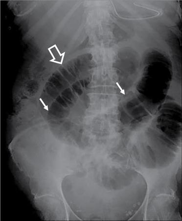
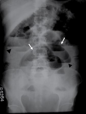
Bowel loop distribution

Normal solid organs
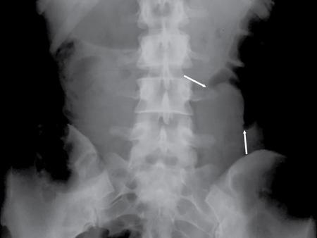
Normal muscles
Normal fat planes
Normal calcifications
Normal bony appearance
Pathological appearances
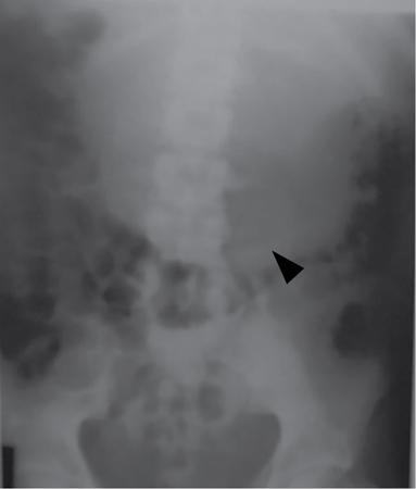
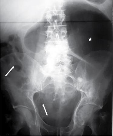
Bowel related
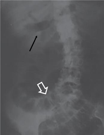
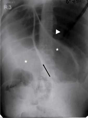
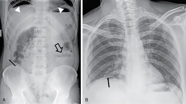
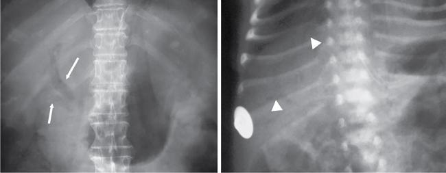
Abnormal air shadows

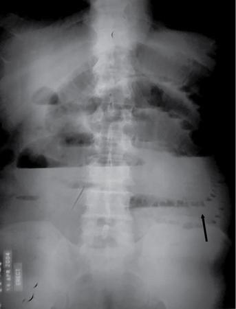
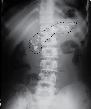
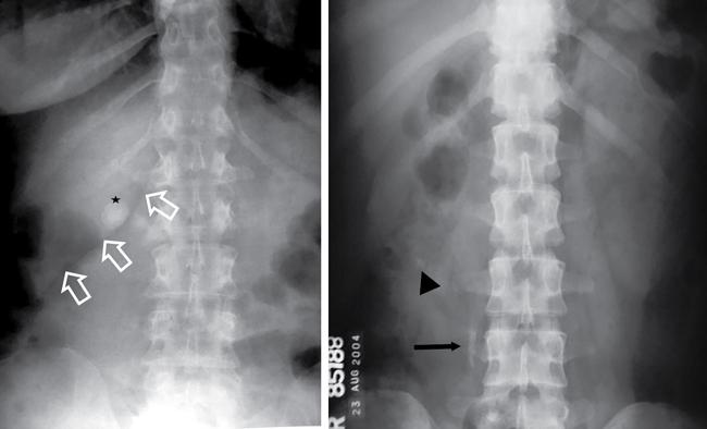
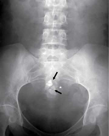
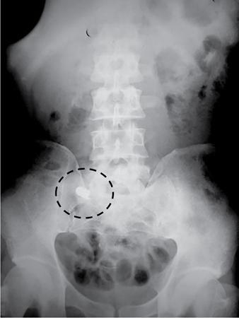
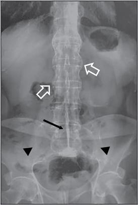
Abnormal calcifications
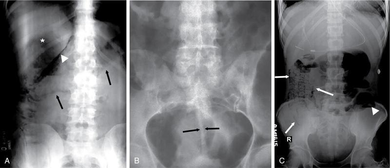
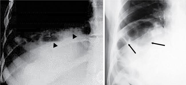
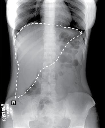
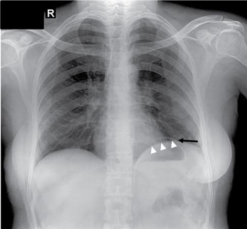
Fluid-related pathologies
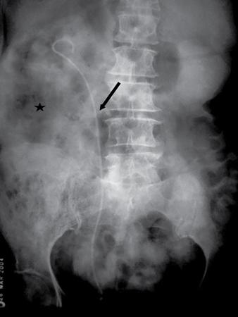
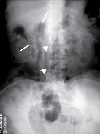
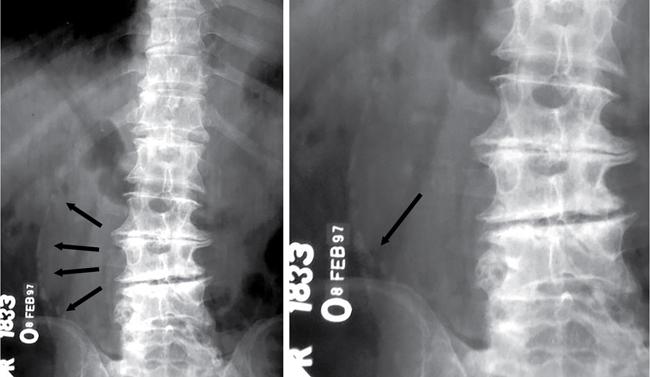
Soft tissue lesions
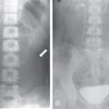
Foreign bodies
Bony pathologies
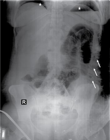
Incidental chest findings
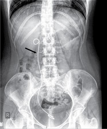
Iatrogenic structures
Subcutaneous abnormalities
Approach to reading an abdominal radiograph
Take home message
Introduction
Indications
Contraindications
Contrast media
Technique
Equipment
Patient preparation
Positioning (Table 7.1.2.1)
Imaging techniques of abdomen and pelvis
7.1.1
7.1.2