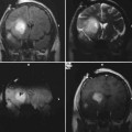
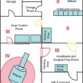
10 In this chapter we describe our technical approach to interventional magnetic resonance imaging (iMRI) guided deep brain stimulator (DBS) electrode placement, based on 53 DBS lead insertions into the subthalamic nucleus (STN) in patients with Parkinson’s disease. The conceptual foundation for the interventional MRI approach to STN-DBS derives from prior experience of our group and others with the standard technique: frame-based stereotaxy with microelectrode guidance. The criteria for successful STN lead placement have been physiologic (region in which microelectrode recording detected STN cells including cells with movement-related responses), or clinical (lead placements that resulted in successful reduction in parkinsonian symptoms). During the past 10 years, many groups have performed post hoc correlation of lead location by postoperative MRI with single unit physiology,1–4 thresholds for stimulation-induced adverse events,5–7 and clinical success.6,8–15 These studies have shown that the STN can be visualized on MRI by its T2 hypointensity, and that the dorsolateral region of the MRI-defined STN reliably contains movement-related cells. Brain coordinates predicting clinical success have been elucidated.6,8–15 This experience provided a conceptual justification for the use of imaging criteria alone to define and confirm accuracy of target placement. The technique evolved as an extension of the prior work of Hall and Truwit in high-field MRI-guided brain biopsy,16,17 described in earlier chapters. The prior biopsy work utilized a smaller “joystick” aiming device (Medtronic Navigus, Medtronic Navigation, Inc., Louisville, CO), whereas the present work employed a skull-mounted device (Medtronic NexFrame, Medtronic, Inc., Minneapolis, MN) that utilizes a “rotate/translate” mechanism, providing finer control at the expense of a less-intuitive aiming paradigm. Our approach uses a standard configuration (closed bore) 1.5 T MRI that is located in a radiology suite rather than an “intraoperative” MRI specifically configured for neurosurgery. Key features of this approach are as follows. (1) Planning, insertion, and MRI confirmation of DBS lead placement are integrated into a single procedure while the patient is on the MRI gantry. (2) The platform for inserting the DBS lead is a burr hole mounted trajectory guide rather than a traditional stereotactic frame and arc system. (3) Target coordinates are defined with respect to the MRI isocenter rather than with respect to a separate stereotactic space using fiducial markers. (4) Patients are under general anesthesia in the supine position and no microelectrode recordings (MER) or test stimulation are performed. (5) Target images are acquired after burr hole creation and intracranial air entry, reducing the potential for errors associated with “brain shift” that can occur with conventional techniques in between image acquisition and probe insertion. Specialized devices and MRI-compatible equipment used are listed in Table 10.1, and MRI protocols in Table 10.2. Patients were allowed to take their usual morning dose of antiparkinsonian medications. After premedication with midazolam and fentanyl, general anesthesia was induced with propofol in a room adjacent to the MRI suite. Anesthesia was maintained with sevoflurane and intermittent fentanyl and vecuronium boluses. Ventilation was adjusted to maintain end-tidal CO2 between 35 and 40 mm Hg. After placement of an intraarterial catheter into the wrist, patients’ heads were placed into a carbon fiber headholder designed to mount directly to the MRI gantry. The frontal area was shaved using clippers. An array of four flexible surface coils positioned at the sides, top, back, and front of the head, was used for MR signal reception (Fig. 10.1).
Implantation of Deep Brain Stimulator Electrodes Using Interventional MRI
Description of Procedure
Patient Preparation and Positioning
Item | Manufacturer | Description |
Philips Intera 1.5 T Intraoperative MRI | Philips Healthcare, Andover, MA | Bore dimensions: length 157 cm, diameter 60 cm. Used for routine diagnostic imaging, as well as interventional procedures |
Malcolm Rand Headset | Integra Life Sciences (Plainsboro, NJ) | MRI-compatible carbon-fiber headholder |
Stimloc cranial base and cap | Medtronic, Inc. (Minneapolis, MN) | For long-term cranial fixation of permanent electrodes. This device is currently being used at University of California-San Francisco for most DBS lead implants. |
NexFrame trajectory guide and alignment stem | Medtronic, Inc. | Disposable skull-mounted aiming device |
NexFrame peel-away introducer | Medtronic, Inc. | A standard peel-away introducer design intended to be used in conjunction with the NexFrame family of trajectory guides to deliver devices into the brain |
Ceramic stylet for NexFrame peel-away introducer | Medtronic, Inc. | A nonmetallic rigid stylet that fits the inner diameter of the peel away introducer, for use in inserting the introducer into the brain |
Model 3389 28 cm DBS electrode | Medtronic, Inc. | One of a family of DBS electrodes currently used for DBS implantation procedures. The length (28 cm) is shorter than that used in standard frame-based procedures. |
Titanium stylet for DBS electrode | Medtronic, Inc. | Custom MRI-compatible stylet associated with relatively low MR artifact |
Gas-powered MRI compatible cranial drill | Anspach, Inc. (Palm Beach Gardens, FL) | The nitrogen tank used to power the drill is not MRI-compatible and is kept outside of the MRI room. |
Titanium surgical instruments | KMedic Instruments (Kenosha, WI) | Set includes Adson forceps, Metzenbaum scissors, Mayo scissors, 3 mm Kerrison rongeur, Penfield dissectors, DeBakey forceps, hemostats, needle |
Trajectory Planning for Burr Hole Location
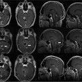
Patients were then moved into the bore of the MRI. An MRI-compatible anesthesia machine was used. A landmark was established on the frontal scalp near the presumed coronal suture and advanced to magnet isocenter. A gadolinium-enhanced volumetric gradient echo MRI was obtained (scan parameters in Table 10.2, protocol 1) parallel to the line between the anterior commissure and posterior commissure (AC-PC line). On the MRI console, approximate anatomic targets were selected bilaterally at a point 12 mm lateral, 3 mm posterior, and 4 mm inferior to the midcommissural point. (This target was used only for trajectory planning; final anatomic target selection was performed in a subsequent step described below.) Single-slice obliqued parasagittal reformatted images were reconstructed that passed through the approximate targets, but avoided the lateral ventricle. A trajectory that avoided sulci and cortical veins was then selected on the oblique image (Fig. 10.2). At the point where the trajectory crossed the scalp, a rapidly updating “MRI fluoroscopy” sequence (Table 10.2, protocol 2, described further below) was prescribed with its center at the intended entry. The surgeon reached into the bore of the magnet and manually placed an MRI visible pointer at the intended entry. The entry point was marked on the scalp with a pen, the patient moved to the back of the bore, and the skull marked percutaneously by injecting methylene blue through a 22-gauge needle at the scalp entry site.
Initial Exposure and Mounting of Trajectory Guide
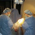
The frontal area was prepped and draped with an MRI bore drape designed to keep the surgical field sterile yet tolerate head movement between the center and back of the bore (a distance of ~1 m) (Fig. 10.3A).
Related posts:
Stay updated, free articles. Join our Telegram channel

Full access? Get Clinical Tree


