Fig. 8.1
Three small ultrasound systems ranging in price from about $50,000 to $2,100
Other key requirements for any imaging device are that it being easy to use and maintain, and that it being able to transfer images electronically. The DICOM [1] (digital imaging and communications in medicine) standard is the means by which medical imaging devices transfer images electronically. It consists of both communication protocols that allow machines to communicate with one another, and a file format that allows information about the patient, medical problem, and how the image was created, to be transmitted along with the images. The DICOM image format is similar to the Tagged Image File Format (TIFF [2]) used for nonmedical images in that information about the image and how it was created resides in “tags” located in the header. Each tag carries some specific form of patient, instrument, or image format information. For example, DICOM tag 0010, 0010 titled “PN” contains the patient name and can have a maximum length of 64 bytes [3]. The DICOM protocols and format are the standard for image transfer from medical devices, but unfortunately many inexpensive ultrasound imaging systems do not include support for DICOM. It can be added if the manufacturer is willing, since there are a number of freeware toolkits such as DCMTK [4] that can be used to help implement DICOM on a specific system.
Other transfer formats could be used including transfer of JPEG and/or AVI files, but the appropriate patient identification information would have to be transferred as a separate file, raising the issue of having unidentified or misidentified images should the identification file get corrupted or deleted. Also, such a custom transfer process could not be expected to work correctly for any devices other than the few it was created specifically for. Once implemented, a DICOM protocol should work with any other device also using DICOM.
A physical means of transporting the image data to the next step in the image transfer chain is also needed. Most systems support wired Ethernet and universal serial bus (USB). A rapidly expanding group of devices also support wireless Ethernet, often termed Wi-Fi. Wired data transfer from the imaging device is preferable because of its higher speed unless the device must be portable. In the case of a portable device, transfer via Wi-Fi or even a 3G or 4G cellular network may be acceptable. Exporting the data to a USB hard disk or other memory device, and then physically transporting the memory device to a display workstation or the next data transfer point, is an old-fashioned but reliable way to make transfers. This is an excellent backup method even if a wireless or wired network connection is normally used.
Step Two: Apply Data Compression
The next step in transporting an image or images is to apply data compression. The purpose of this step is to conserve bandwidth as the image is transmitted to the location where it will be interpreted. If that location is local and within range of Wi-Fi, then bandwidth may not be an issue, then either no compression or lossless compression may be employed. A number of lossless compression schemes exist, and they are able to achieve a modest compression level of approximately 2:1 (meaning that the compressed data is ½ of the uncompressed).
For transmission over longer distances, much greater compression is usually required as either maximum data rates may be very slow (as noted above) or high data rates could be achievable but would be very costly. Modern lossy compression schemes employing variants of MPEG-4 are extremely useful for compression of series of images such as in CT and MRI (not radiography) where one image is similar to the next. The compression efficiency is due to the fact that the compression algorithm can make use of the adjacent pixels in the same image and in adjacent images to help reconstruct what a given pixel in the image must be. Other image compression protocols such as JPEG can only use nearby pixels in the same image. Recent coder-decoders (CODECs) that are efficient in encoding series of images include MPEG-4, part 2, DivX, and XviD. These are much more effective protocols than JPEG2000 or JPEG; they can compress 40–80 MB video files down to only about 300–400 KB while producing images that are almost indistinguishable from the original [5] (Fig. 8.2). Newer CODECs such as H.264, MPEG-4 part 10 (AVC), and Dirac are more effective still, producing files about half the size of MPEG-4 part 2 [6]. The new High Efficiency Video Encoding Codec, HEVC (H.265), is expected to cut the data rate and file size by another 50 % compared with H.264 while producing little discernible reduction in quality [7]. In practical terms this level of compression could result in an entire series of CT or ultrasound images being compressed down to about 100–200 kB, half the size of a single image.


Fig. 8.2
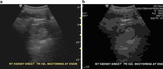
Comparison of video compression to single image compression. A transverse image of the right kidney appears nearly identical to the original when compressed by XviD to a total file size of approximately 400 kB for 40 images (a). Images of the same series when compressed individually to the same total file size using JPEG compression yield images that are not even recognizable as ultrasound images (b)
Step Three: Transmit Data
Several modes of electronic transmission are potentially available in low-resource regions. Cellular network transmission is widely available although speeds can be quite low. Cellular transmission capability can be built into the imaging device, but it is often more practical to send the data to a network gateway, an inexpensive laptop PC connected via cellular modem to the network. This prevents the imaging system from getting overloaded with transmission and retransmission tasks in the event of network instability and also allows upgrading the transmission software and hardware without changing the imaging device. It also allows for the addition of imaging devices that use the same gateway. Communication between the network gateway and the imaging devices can be by wired or wireless Ethernet. Both options are low cost and low maintenance. Wireless allows the imaging device to be moved around more conveniently while leaving the network gateway in one place.
Wired Internet service is available in many low-resource environments and is a faster alternative to cellular when the cost is reasonable. Data rates of between 125 Kbps and 1 Mbps may be expected. For really remote sites, satellite links can be used, but the cost for such a connection may be very high and is probably not sustainable in the long term. A satellite connection that can be turned on only when needed could be a solid backup system, but negotiating a plan suitable for intermittent use at a reasonable cost could be challenging. Some additional useful characteristics for a network gateway are:
1.
Ability to back up studies to CD, DVD, or USB flash drive for “sneakernet” manual transfer to a reading site should the network connection be interrupted for an extended period.
2.
Ability to connect to an external antenna and/or signal booster to increase signal for borderline signal reception areas.
3.
Low power consumption. Less than 20 W is desirable and achievable for gateway, modem, and switch/router combined.
4.
Adequate storage for queued studies awaiting transmission and as a backup location for studies. In addition to the system storage, a 500 GB – 1.5 TB USB-powered external drive is inexpensive, requires low power, and provides massive backup capability.
In addition to the Internet connection, suitable software will be needed to perform the data compression, transmission, and decompression. For regions where network instability is the rule, auto-restart of the modem software as well as selective retransmission of only those data packets that failed to be received is useful. Some modems advertise automatic restart as a feature, but most often one will have to experiment with various models to find one with appropriate software. Some modems have freeware that will perform auto-restart. Basic transmission of data can be accomplished by a number of file transmission programs. The Unix utility rsync can be used, for example, to ensure that data files not already present on the receiving system are transferred, but this utility (also available for Windows) will resend a complete file if data flow is interrupted during transfer. This is not ideal for a network subject to frequent interruptions such as many cellular networks. So a more sophisticated transfer that (1) retransmits portions of files not properly received, and (2) monitors network performance to adjust packet size and minimize packet loss during transmission, is desirable. Additional features that are useful if not critical are:
1.
A logging utility that sends the logs periodically to the receiving site for evaluation
2.
An easy-to-use graphical user interface with an equivalent command line interface that can be used remotely using minimal bandwidth—or an alternative method of issuing remote commands to the software (and receiving responses) using minimal bandwidth
3.
Detailed error messages that inform the system administrator of likely causes of transmission failures
4.
Automatic correction of common problems with data transmission
5.
Email transmission of warning messages regarding transmission failures, number of images awaiting transmission if it exceeds a certain threshold, or other system problems
Step Four: Assure Access to Images by Qualified Interpreters
The physicians or other healthcare workers assigned to interpret the images may be local, regional, or remote to the site where images are being acquired. Local interpretation can be accomplished by connecting a reading workstation to the imaging source by an Ethernet connection or wireless Ethernet connection. A wired connection is faster and with modern equipment gigabit Ethernet (approximately 1 Gbps transmission rate, known as 1000baseT1) is feasible at low cost if the distance to the workstation is short (<100 m) using Category 5, 5e, or 6 Ethernet cable. For longer distances up to 500 m or more, 1000baseSX Ethernet using fiber-optic cabling is an option but is of higher cost and may not be readily available. Other versions of gigabit Ethernet using fiber-optic cables can communicate over distances of 70 km or more.
On the software side, the transmission protocol for the local (and remote) connection should be DICOM, since the DICOM standard provides proper patient and study identification. All high performance image viewing software supports DICOM, making daily workflow much easier. This means that the imaging device should support DICOM. The degree of DICOM support is listed in a DICOM conformance statement, but at minimum the imaging device should be able to connect with a DICOM service class provider (SCP) and transmit images with a properly formatted DICOM header, correctly windowed and calibrated for image measurement on the reading viewer or workstation.
For a local reading station, having DICOM viewing software and a DICOM server to support reception and storage of the images is the optimal approach. Both the server software and the viewer can reside on the same computer. A large number of vendors supply DICOM workstation software at varying prices, and a number of freeware packages exist. Some of the freeware packages differ in that they are not cleared by the FDA, whereas others offer limited functionality and hardware support, often too limited to be of great use. Potential sources of DICOM workstation freeware for Windows include ClearCanvas [8], K-PACS [9], and Onis [10], and for the MacIntosh, OsiriX [11] is a common choice. In some cases, a viewer alone can be used, but storage of cases in this situation is either nonexistent or very limited. A number of vendors also offer DICOM toolkits to help with building new DICOM applications. It may be possible to partner with a PACS vendor and obtain donated software for specific projects.
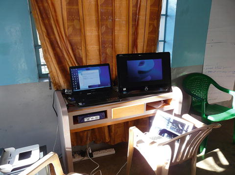
The local reading workstation may simply be a laptop running Windows or it may be a larger system with multiple monitors. Adding a single high-definition (HD) monitor to an inexpensive laptop creates a simple and cost-effective two-screen workstation with one screen for the patient list (the laptop screen) and another for the images (Fig. 8.3). A minimal system consisting of a netbook plus a 21 in. (or larger) HD monitor will perform adequately provided the system is upgraded from Windows 7 Starter (which does not support two independent monitors) to Windows 7 Home Premium or higher and the system is upgraded to 2 GB of memory. A faster system with more memory would of course be more desirable since entire image sets are often held in memory while viewing (to improve responsiveness). For viewing large radiographs, a slightly larger monitor (23–24 in.) rotated to portrait mode may be needed. A monitor with an in-plane switching (IPS) LCD panel is preferable to a “TN” type panel to avoid color and intensity shifts with changes in head position and to provide better gray scale. To add additional monitors to a laptop-based system, inexpensive USB video adapters capable of supporting 1080p or higher resolution are inexpensive and readily available.


