■
Value of a Routine Daily Chest Radiograph in the Intensive Care Unit
Determining Who Needs Imaging
Imaging of an intensive care unit (ICU) patient can be a difficult task that relies on cooperation and teamwork among many members of the clinical care team and technologist. The complexity of these critically ill patients, many of whom have numerous support devices, has led to the practice of daily routine chest radiography, especially of the mechanically ventilated, to assess for changes or complications. However, recent studies have shown that the elimination of daily routine chest radiography does not significantly affect mortality or length of stay in the hospital. According to the American College of Radiology appropriateness criteria, there is no specific need to obtain daily routine chest radiographs. Rather, imaging should be performed when there is a change in clinical status or after initial placement of an endotracheal tube, nasogastric tube, Swan-Ganz catheter, central venous catheter, chest tube, or other life support device due to the risk of complications associated with placement. Follow-up imaging of these support devices is then dependent on the clinical status or concern for new complication rather than on a routine basis.
■
Respiratory
Location of Endotracheal and Tracheostomy Tubes
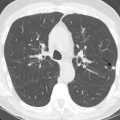
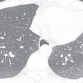
A wide variety of endotracheal tubes exist; the size is chosen based on the patient body habitus. The width is optimally one-half to two-thirds the width of the trachea. Most have an inflatable cuff that seals the trachea, prevents air leaks, and reduces the risk of aspiration. Endotracheal tube position is commonly described as the distance of the tube tip to the carina. The carina normally lies at the level of T4–T5 ( Fig. 39.1A ) or the undersurface of the aortic arch; these are useful landmarks when the carina is not well seen. Ideally, the tube is positioned in the midtrachea, and the tip lies 3 to 6 cm above the carina. Because flexion and extension of the neck may result in a roughly 2-cm descent and ascent of the tube, respectively, some variability in position is not uncommon on serial radiographs. In select circumstances, dual-chamber endotracheal tubes are used and allow selective decompression or aeration of each lung ( Fig. 39.2 ). In patients with tracheostomy tubes, the tip is ideally one-half to two-thirds of the width of the trachea and one-half to two-thirds of the distance from the stoma to the carina. The tip should not be resting against the tracheal wall.


When an endotracheal tube is advanced too inferiorly, the tip preferentially enters the right main stem bronchus because it is more vertically oriented. This may result in left lung atelectasis (see Fig. 39.1B ). When advanced farther, the tip will enter the bronchus intermedius and obstruct the right upper lobe bronchus, resulting in right upper lobe atelectasis. When the tube is not deep enough, the tip may enter the esophagus. Close attention to the relationship of the tube and tracheal air column is mandatory. When in the esophagus, the tube may be left lateral to the tracheal margins, and the stomach may be distended with air. A right posterior oblique or lateral radiograph may provide better delineation of the pertinent anatomy. If the tube is outside the confines of the tracheal air column and not within the esophagus, tracheal rupture should be considered, especially in the setting of pneumothorax, pneumomediastinum, or subcutaneous emphysema. Overinflation of the tube cuff or balloon, which may manifest as bulging of the tracheal wall, may acutely lead to tracheal perforation or chronically result in stricture or scarring.
Positioning of Chest Tubes
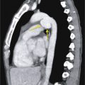
The desired position of a chest tube is heavily dependent on the goals of tube placement and the physical properties of air and fluid. Because air accumulates anteriorly and superiorly, chest tubes placed primarily for a pneumothorax should be positioned accordingly. Conversely, free fluid settles in the dependent and posterior portions of the lung, and tubes placed for pleural effusions or hemothorax are directed toward the base. Finally, loculated fluid collections may require more directed placement.
Most large-bore chest tubes have a radiopaque line denoting the point just distal to the last fenestration in the tube (see Fig. 39.2A ). This line should be in the thoracic cavity. If the side hole is outside the pleural space, tube function may be compromised, and subcutaneous emphysema may result (see Fig. 39.2B ). Tubes within the fissures may also function poorly as the pleural surfaces appose and obstruct the tube.
Location of Enteric Tubes
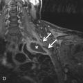
Nasogastric and orogastric tubes can be used for feeding or decompression. The side port of the tube should be below the gastroesophageal (GE) junction to ensure proper function and reduce the risk of aspiration. If the sideport is not well visualized, approximately 10 cm of the tube should be below the GE junction. Tubes used for feeding often have a weighted tip. This tip should be postpyloric.
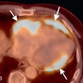
The course of any tube with the tip above the diaphragm should be closely evaluated to ensure that it is not within the trachea or esophagus ( Fig. 39.3 ). A tube with a completely vertical orientation in the abdomen may suggest perforation. In cases such as esophagectomy with gastric interposition, an intrathoracic tube location may be desired. A hiatal hernia or intrathoracic stomach may also lead to an altered tube location.


■
Cardiovascular
Ideal Location for a Central Venous Catheter
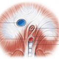
The ideal location for the tip of a central venous catheter depends on its intended use and varies according to professional societal guidelines. Although there is no consensus, the cavoatrial junction is a commonly accepted landmark signifying appropriate positioning. A catheter with a high tip may have poorer flow rates and be more prone to malfunction and thrombosis. There is also a risk of superior vena cava (SVC) erosion, especially with a short left-sided catheter, when the tip and catheter course are relatively perpendicular to the caval wall. With a low tip, there is a risk of arrhythmia, and reports of cardiac tamponade due to gradual vascular erosion have been presented, although many of these reports were older studies with more rigid catheters that are no longer commonly in use. The SVC empties into the right atrium through a thickened ring of tissue formed by the crista terminalis and dividens. The cristae represent the embryonic transition from the sinus venosus to the atrium and form the anatomic cavoatrial junction. Because this is not visible radiographically, landmarks such as the right tracheobronchial angle and carina serve as surrogates. The cavoatrial junction typically resides 3 to 4 cm below these structures. There can be great variability in apparent tip position, with severe under- or overinflation or projectional differences in radiographs.
Catheters that take a vertical course but are to the left of the spine may reside in a left or double SVC, mediastinal or internal mammary vein, or the aorta, or they may be extravascular ( Fig. 39.4 ). When the tip is directed posterolaterally, the catheter may have entered the azygos vein ( Fig. 39.5 ). Mediastinal widening, loss of the aortic silhouette, an apical cap, or mass effect on surrounding structures may be seen in cases of mediastinal hematoma. An apical cap can also be secondary to an extrapleural hematoma.


Common Complications of Central Venous Catheter Insertion
Catheters should be traced to their source to evaluate for kinking or fragmentation. Catheter pinch-off occurs with subclavian lines near the junction of the first rib and clavicle. Repetitive compression by the costoclavicular ligament and subclavius muscle results in catheter fatigue. Initially, distortion is present without luminal narrowing, although this can progress to luminal narrowing or catheter transection or fracture. The distal tip may embolize to the heart or pulmonary artery ( Fig. 39.6 ).


Following new central venous catheter insertion, the radiograph must be carefully evaluated for a pneumothorax on both sides. Although a new catheter may be present on one side, failed attempts at contralateral placement with errant needlesticks are a distinct possibility. A new pleural effusion suggests a hemothorax.
■
Pacemakers and Implantable Cardioverter-Defibrillators
Situating Pacemaker Leads
The specific model and configuration of the pacemaker will depend on the indication. The leads are typically introduced via the left subclavian vein. The initial postplacement radiograph should be closely examined for the presence of pneumothorax or hemothorax and appropriate lead course ( Fig. 39.7A ). One electrode will be directed toward the right ventricular apex. It courses along the base of the right ventricle, left of the midline on the frontal view and anteriorly and inferiorly directed on the lateral radiograph. The tip should be within 2 to 4 mm of the epicardial fat pad; further displacement of the tip may suggest myocardial perforation (see Fig. 39.7B and C ). A second lead may enter the right atrial appendage. On the frontal view, the lead terminates over the right upper heart border, often with a cranially directed curve. On the lateral view, the lead will follow the smooth anterior curve of the midportion of the heart. A third electrode placed into a coronary vein will traverse the coronary sinus and will be directed upward and laterally. On the lateral radiograph, this lead will course posteriorly.