Fig. 1.1
a A single element ultrasonic transducer generating a traveling wave, and b the same transducer receiving the waves scattered from a spherical reflector
The element of this transducer is typically made of a piezoelectric material that converts electrical energy into mechanical motion of the element and vice-versa. Thus, if the transducer is excited by an electrical pulse, as shown in Fig. 1.1a, a traveling pulse of sound will be generated in the water in the form of an acoustic wave. If this wave strikes an object such as a spherical reflector, as shown in Fig. 1.1b, then waves will be scattered from the sphere in all directions and some of that scattered acoustic energy will return to the transducer and will be converted back into electrical energy, amplified, and output as a voltage versus time pulse. Knowing the wave speed of the fluid and the time of arrival of this pulse we can easily determine the distance to the sphere, but other quantitative information such as the size of the sphere, its mechanical properties, etc. are not directly obvious from the measured signal. If one mechanically moves this single element transducer and changes its position and/or orientation, then a collection of measured signals can be obtained and used to help better determine such quantitative information. In fact, with sufficient information obtained from such mechanical motion of the transducer one can even synthesize an ultrasonic image of the sphere. However, mechanical scanning is slow and expensive to perform with a single element transducer setup. A more effective approach to conduct inspections and form images is to use an ultrasonic phased array, where the sound beam can be manipulated electronically. Even with phased arrays, however, one must overcome the indirect nature of the measurement process. Thus, the primary purpose of this book is to describe in detail how the signals and images are formed with ultrasonic phased array systems so that one can extract quantitative information from those phased array measurements and images.
In a phased array setup (Fig. 1.2), the ultrasonic transducer is composed of an array of small piezoelectric elements, where each element can be separately driven and the response of each element independently received. If each of the elements is driven in an identical fashion so that the driving electrical pulses travel in unison and all arrive at the piezoelectric elements at the same time (no relative delay between pulses) then each small element of the array acts effectively like a point source and radiates a spherical wave (the dashed lines in Fig. 1.2 represent the spherical wave fronts), and these spherical waves combine to form a traveling wave pulse, as shown in Fig. 1.2. Except in a region close to the array the sound beam of the array is similar to the beam generated by a single element transducer of the same size as that of the entire array. However, by varying the relative time delays,  , of the driving pulses (where the ensemble of delays is called a delay law), the ultrasonic phased array is able to electronically steer the sound beam generated in different directions, as shown in Fig. 1.3a without requiring any motion of the transducer itself. With an appropriate non-linear delay law, the same array can also generate a focused sound beam as shown in Fig. 1.3b. A more complex combination of these delay laws can simultaneously perform both beam steering and focusing. This flexibility of ultrasonic phased arrays to electronically control the properties of the sound beam can make the collection and use of many ultrasonic measurements rapid and cost-effective. This same flexibility also allows one to rapidly form ultrasonic images, a capability that has been used for many years in clinical applications and is seeing a much broader use recently in industrial NDE inspections.
 , of the driving pulses (where the ensemble of delays is called a delay law), the ultrasonic phased array is able to electronically steer the sound beam generated in different directions, as shown in Fig. 1.3a without requiring any motion of the transducer itself. With an appropriate non-linear delay law, the same array can also generate a focused sound beam as shown in Fig. 1.3b. A more complex combination of these delay laws can simultaneously perform both beam steering and focusing. This flexibility of ultrasonic phased arrays to electronically control the properties of the sound beam can make the collection and use of many ultrasonic measurements rapid and cost-effective. This same flexibility also allows one to rapidly form ultrasonic images, a capability that has been used for many years in clinical applications and is seeing a much broader use recently in industrial NDE inspections.
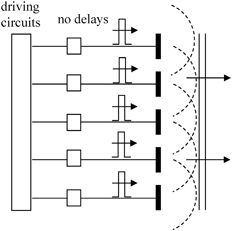
Fig. 1.2
An ultrasonic phased array, where the driving electrical pulses for each element arrive in unison, i.e. with no time delay relative to each other
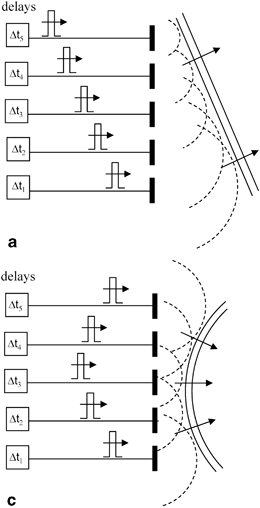
Fig. 1.3
a An ultrasonic phased array where a set of delays are used to steer the sound beam of the array and, b the case where a set of delays produce a focusing of the sound beam
Relative time delays for each element can also be used for modifying the characteristics of the signals received by an array. Fig. 1.4a shows the case where a plane wave front arrives at an array. As this wave strikes each element of the array in succession, a series of electrical pulses will be generated as shown. If relative time delays,  , are applied to these received signals so that all of the signals occur at the same time, then they can be summed to generate a single, large output signal. Note that this summed signal is similar to what would be measured by a single element transducer whose face was at normal incidence to the incoming wave so that the entire surface of the transducer was excited simultaneously by the incident wave. Thus, this reception delay law effectively acts much the same as a single element receiving transducer oriented to face the incoming wave. Similarly, in Fig. 1.4b, where the incident wave front is curved, relative time delays can be applied on reception to align all the signals from the elements so they also can be summed. This delay law is then analogous to what would happen with a focused single element transducer on reception.
 , are applied to these received signals so that all of the signals occur at the same time, then they can be summed to generate a single, large output signal. Note that this summed signal is similar to what would be measured by a single element transducer whose face was at normal incidence to the incoming wave so that the entire surface of the transducer was excited simultaneously by the incident wave. Thus, this reception delay law effectively acts much the same as a single element receiving transducer oriented to face the incoming wave. Similarly, in Fig. 1.4b, where the incident wave front is curved, relative time delays can be applied on reception to align all the signals from the elements so they also can be summed. This delay law is then analogous to what would happen with a focused single element transducer on reception.
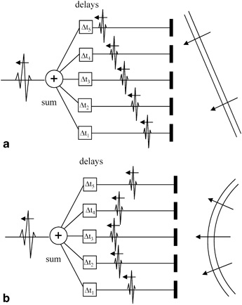
Fig. 1.4
a Applying variable time delays and a summation on reception for receiving a wave arriving at angle to the array, and b applying variable time delays and a summation on reception for receiving a curved wave front arriving at the array
Because an ultrasonic phased array can transmit/receive with each element of the array independently of the other elements, it also is possible to apply individual amplitude weights ,  , to the elements on either sound generation and reception (or both) (see Fig. 1.5). The ensemble of such amplitude weights is called an apodization law. In Chap. 3, we will describe the most common apodization laws that are used to tailor the important acoustic radiation characteristics of a phased array.
 , to the elements on either sound generation and reception (or both) (see Fig. 1.5). The ensemble of such amplitude weights is called an apodization law. In Chap. 3, we will describe the most common apodization laws that are used to tailor the important acoustic radiation characteristics of a phased array.
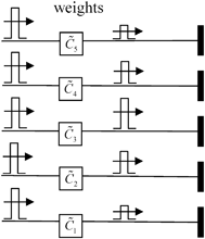
Fig. 1.5
An ultrasonic phased array where amplitude weights are applied to the driving pulses, corresponding to an apodization law applied to the sending elements
The ability to use general delay laws and apodization laws on generation and reception makes an ultrasonic phased array a very versatile and effective device for conducting ultrasonic tests. It is important that engineers and scientists who use this ultrasonic phased array technology understand the basic principles that govern the behavior of phased arrays and the important parameters that control their performance. It is also important to know how the characteristics of ultrasonic phased array systems can be exploited to help overcome the indirect nature of measured ultrasonic responses and better determine the properties of the object being examined, as discussed previously.
This book will describe in detail the fundamentals of ultrasonic phased array systems, using a combination of models and measurements to characterize the behavior of the arrays that are typically used in NDE inspections of materials and structures. Two references to those fundamental concepts we will mention often are the books listed as [1,2] in the References at the end of this Chapter. Throughout this book those two references will be listed simply as [Schmerr] and [Schmerr-Song], respectively. Since our focus is on the use of phased arrays in NDE settings the behavior of ultrasonic arrays when interacting with biological systems and medical applications of arrays will not be discussed here but the reader can find a number of other very good sources for those important topics [3,4,5]. Also, see [6] for an overview of ultrasonic NDE applications.
1.2 Linear and 2-D Arrays
The shape of the piezoelectric elements in an array can be quite general but rectangular elements are often used in practice because they are cost effective to manufacture. Figure 1.6 shows a set of identical rectangular elements where the length of each element in the x-direction,  , is much smaller than its length in the y-direction,
  . This configuration is called a linear array . The gap length,
  , between elements in the x-direction is normally the same for all pairs of elements in such an array. This gap length is also called the kerf of the array. Another important parameter is the element-to-element spacing,
  , as shown in Fig. 1.6. This parameter is called the pitch of the array. Obviously, from the geometry the pitch is
  . Because there are multiple elements in only one dimension in a linear array, time delay laws applied to the elements of a linear array can only steer the beam in the x-z plane and generate cylindrical focusing along lines parallel the y-axis that pass through various points in the x-z plane. Even with this restriction a linear array can be a very effective tool for conducting NDE inspections.
 , is much smaller than its length in the y-direction,
  . This configuration is called a linear array . The gap length,
  , between elements in the x-direction is normally the same for all pairs of elements in such an array. This gap length is also called the kerf of the array. Another important parameter is the element-to-element spacing,
  , as shown in Fig. 1.6. This parameter is called the pitch of the array. Obviously, from the geometry the pitch is
  . Because there are multiple elements in only one dimension in a linear array, time delay laws applied to the elements of a linear array can only steer the beam in the x-z plane and generate cylindrical focusing along lines parallel the y-axis that pass through various points in the x-z plane. Even with this restriction a linear array can be a very effective tool for conducting NDE inspections.
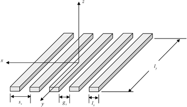
Fig. 1.6
The elements of a linear array
One common application of such linear arrays is to place the array on a low speed wedge in contact with an adjacent solid, as shown in Fig. 1.7, to generate an array-based angle beam vertical-shear (SV) wave inspection setup, where phasing of the array allows the shear wave to be steered and focused at various angles, θ, in the solid.
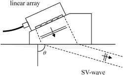
Fig. 1.7
An array-based angle beam shear wave inspection setup
Figure 1.8 shows a two-dimensional array of small, identical rectangular elements of lengths l x and l y , respectively, in the x– and y-directions and where there are uniform gap lengths  and
and  between elements in each of the x– and y-directions so that the pitches in each of these directions are given by
  ,
,  . Since time delays that vary in both the x– and y-directions can be applied to the elements of a two-dimensional array, it is possible to steer and focus the beam of a 2-D array in a very general manner.
 and
and  between elements in each of the x– and y-directions so that the pitches in each of these directions are given by
  ,
,  . Since time delays that vary in both the x– and y-directions can be applied to the elements of a two-dimensional array, it is possible to steer and focus the beam of a 2-D array in a very general manner.
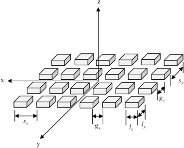
Fig. 1.8
A two-dimensional array of uniformly spaced, identical rectangular elements
1.3 Modeling Ultrasonic Phased Array Systems
This book will exam in detail all the components of an ultrasonic phased array flaw measurement system (see Fig. 1.9


Stay updated, free articles. Join our Telegram channel

Full access? Get Clinical Tree


