Fig. 5.1
Showing typical power button used on a laptop ultrasound device
Preset
The preset button or the exam button is perhaps one of the most important buttons in an ultrasound system. Selecting the right present for that particular region of the body makes scanning much easier. Built-in software assists not only with labeling and measurement but will make the video image much clearer. For example, if you were scanning a pregnant patient in the second trimester and did not select the obstetrical preset for the second trimester, you will not be able to calculate the gestational age using the fetal parameters such as BPD, FL, or AC if you were scanning the patient using abdominal settings. Also note that the acoustic output of the probe may be higher than is recommended for fetal ultrasound (Fig. 5.2a, b).

Fig. 5.2
Showing the preset button (a) also labeled as an exam button (b) on an ultrasound device
Freeze
Most modern ultrasound systems are always recording and dumping data as they record new data. So, at any point in time when you press the freeze button , the user can scroll back through the previous few frames on the internal memory of the device. Once you unfreeze, the data from the previous scan is deleted unless specifically saved by the user. The amount of data that is stored while scanning can be adjusted by the user by logging into the system configuration or system settings. Small pocket ultrasound devices may not allow you to manipulate such settings (Fig. 5.3).

Fig. 5.3
Showing the freeze button on a laptop ultrasound device. Press to freeze an image and press again to unfreeze and start real-time scanning
Gain
The gain control knob allows the user to increase or decrease the overall brightness or darkness of an image. As a rule, try to represent clear fluids or blood with the black color (anechoic). Try to optimize the image to represent the true characteristics of the organ being scanned. Turn the knob clockwise to increase the overall image gain and counterclockwise to reduce the overall brightness of the image on the monitor. The auto button in the center can automatically optimize the gain setting. It works best during spectral Doppler mode.
Keep in mind that the gain control knob will increase or decrease the brightness only during B-mode imaging. If you are using color Doppler then it will increase or decrease the sensitivity of the color Doppler display and during spectral Doppler it will enhance or reduce the brightness of the spectral Doppler tracing (Fig. 5.4).

Fig. 5.4
Showing the gain knob
Depth
Depth control lets you adjust the maximum depth of the ultrasound region being scanned and displayed on the monitor. Try to adjust the depth to show the structure of interest completely without cropping it and also add 1–2 cm margin to make sure there is no pathology around the structure. For example if you are scanning the abdominal aorta, then make sure that the posterior wall of the abdominal aorta is included as well as 1–2 cm beyond the posterior wall of the abdominal aorta (Figs. 5.5, 5.6, and 5.7).

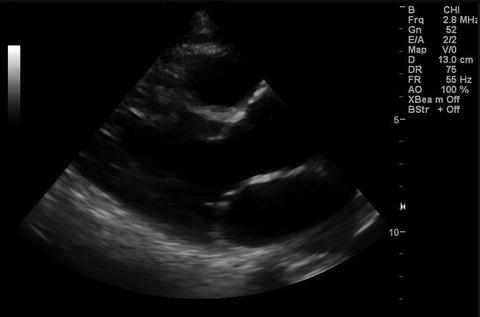

Fig. 5.5
Showing depth control buttons
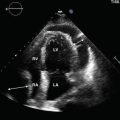
Fig. 5.6
Showing the left parasternal long axis (PLAX) view of the heart with proper depth settings. The depth setting in this example is set at 13 cm
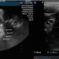
Fig. 5.7
Showing the left parasternal long axis (PLAX) view of the heart wrong depth settings. The depth is set too deep and thus the heart looks much smaller in size. Note that the depth setting in this example is set at 30 cm
Focus
The focus function allows the user to adjust the level of the focus of the ultrasound beam onto different structures during real time scanning. For example, if you were performing a scan of the abdominal aorta then make sure that the focus is at the level of the aorta in the image. Image quality at the level of the focus is the sharpest. Beyond the focus the image quality begins to degrade. Some ultrasound systems only have presets and will not allow adjustment of the focus level. You can also increase or decrease the focus points. See images below. Increasing the focus points may at times cause the frame rate (FR ) to decrease (Figs. 5.8 and 5.9).


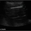
Fig. 5.8
Showing ultrasound image obtained with one focal point at the level of interest. See white arrow indicating focus level indicator
Fig. 5.9
Showing ultrasound image obtained with multiple focal points
Time Gain Compensation (TGC)/ Depth Gain Compensation (DGC)
The TGC is also designated as DGC by some manufacturers. The TGC control allows the user to select the brightness or darkness of an ultrasound image at different levels. The aim should be to have an ultrasound image that is evenly exposed or illuminated. Some individuals also use the liver as a reference to set the TGC settings. See images below (Figs. 5.10, 5.11, and 5.12).


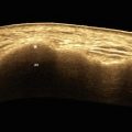
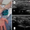
Fig. 5.10
Showing an oblique view through the right lobe of the liver with correct TGC settings
Fig. 5.11
Showing TGC/DGC control on a typical laptop ultrasound device . This function may not be available on some smaller ultrasound devices and may be controlled automatically by the device
Fig. 5.12
Showing ultrasound image obtained by incorrect TGC setting in the near field
Measurement
As mentioned earlier, it would be critical to select the appropriate preset before attempting to scan the patient. You could scroll back from the last frozen image on the display and select the optimal image frame and proceed to perform standard ultrasound measurements. These details can be found in the user’s manual of the device (Fig. 5.13).

Fig. 5.13
Showing a measurement function activation button
Storing Images/Video Loops
The image storing capability will vary depending upon the ultrasound device and the manufacturer options. Since most modern ultrasound systems are digital so you have a variety of image storage options. You could store the image or a video loops lasting few seconds on the internal hard drive of the device or a USB flash drive or burn a CD or DVD or even transmit to a server to store the image on a PACS system. You still do have the ability to print on a thermal digital printer designed specifically for ultrasound image printing (Figs. 5.14 and 5.15).


Fig. 5.14
Showing the image and or video loop save buttons. In this example they are programmable and user defined. Some ultrasound systems may have fixed save functions allocated by default
Fig. 5.15


Showing a designated printer function button (this cannot be programmed to do other save function)
Related posts:
Stay updated, free articles. Join our Telegram channel
Full access? Get Clinical Tree
