. As seen in Chap. 2, a large transducer will generate a highly directional (well-collimated) beam of sound that travels in a direction normal to the face of the transducer. We will start from the high frequency 2.31) which can be written as:
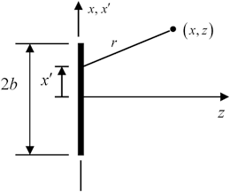
Fig. 3.1
A large single element transducer radiating into the region z > 0

(3.1)
The radius  but since the sound beam is essentially traveling in the z-direction, if we are not too close to the face of the transducer the beam will primarily be in the region where
  and r can be expanded in that small parameter. This approximation is called the paraxial approximation. In this approximation the radius is given by
 but since the sound beam is essentially traveling in the z-direction, if we are not too close to the face of the transducer the beam will primarily be in the region where
  and r can be expanded in that small parameter. This approximation is called the paraxial approximation. In this approximation the radius is given by
![$$ r=z\sqrt{1+\frac{{{(x-{x}')}^{2}}}{{{z}^{2}}}}\cong z\left[ 1+\frac{{{(x-{x}')}^{2}}}{2{{z}^{2}}} \right] $$](/wp-content/uploads/2016/05/A314073_1_En_3_Chapter_Equ2.gif)
(3.2)
so Eq. (3.2) becomes
![$$ p(\mathbf{x},\omega )=\rho c\sqrt{\frac{k}{2i\pi }}\frac{\exp (ikz)}{\sqrt{z}}\int\limits_{-b}^{+b}{{{{\bar{v}}}_{z}}({x}',\omega )\exp \left[ \frac{ik{{(x-{x}')}^{2}}}{2z} \right]d{x}'}. $$](/wp-content/uploads/2016/05/A314073_1_En_3_Chapter_Equ3.gif)
(3.3)
If we make the change of variables  and assume we have piston behavior then
 and assume we have piston behavior then
(3.4)
which can be written as the difference of two Fresnel integrals as
![$$ p(x,z,\omega )=\rho c{{v}_{0}}\sqrt{\frac{1}{2i}}\exp (ikz)\left[ F\left( \sqrt{\frac{k}{\pi z}}(x+b) \right)-F\left( \sqrt{\frac{k}{\pi z}}(x-b) \right) \right], $$](/wp-content/uploads/2016/05/A314073_1_En_3_Chapter_Equ5.gif)
(3.5)
where the Fresnel integral,  , is defined as
 , is defined as
(3.6)
The MATLAB® function fresnel_int(x) defined in Code Listing C.8 evaluates the Fresnel integral numerically. This function is used in the beam model fresnel_2D(b, f, c, e, x, z), given in Code Listing C.7, which computes the normalized pressure wave field of a large 1-D piston element transducer. The calling sequence for this function is
 , is calculated. Figure 3.2 shows a comparison of both on-axis and cross-axis pressure profiles for a 12 mm long element radiating at 5 MHz into water as computed with the Fresnel integral model and the multiple line source model. It can be seen that the Fresnel integral model accurately predicts the wave field in these plots. This is because the paraxial approximation is well satisfied for the highly directional beam emitted by an element that is large with respect to the wavelength. For the small elements present in arrays, this approximation can only be used in a much more limited sense. However, the Fresnel integral model gives us a direct way to use a model of a large, single element transducer to study the phasing effects used by arrays to steer and focus beams, as will be shown in the next section.
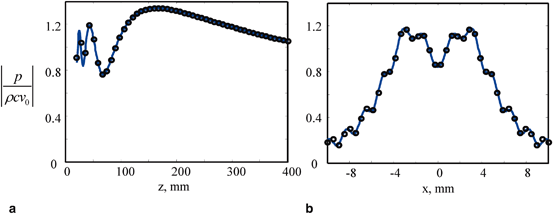
Fig. 3.2
Comparison of the multiple line source model with the Fresnel integral model for the transducer parameters; b = 6 mm, f = 5 MHz, c = 1500 m/s. a The on-axis normalized pressure versus distance z, and b the cross-axis normalized pressure at z = 60 mm versus the distance, x. Solid line—multiple line source model, Circles—Fresnel integral model
3.2 Beam Steering and Focusing of a Large Element
As discussed in Chap. 1, an array of elements can be steered and/or focused by applying an appropriate set of delays, called a delay law, to the elements. A delay in a time domain response, however, corresponds to multiplying the frequency domain response (frequency spectrum of the time domain signal) by a phase term that is linear in frequency and proportional to that delay. This is just the consequence of the properties of the Fourier transform since if a time domain function,  , has a frequency spectrum (Fourier transform),
  , then a delayed signal,
  , where
  is the delay, has a spectrum
  [Schmerr]. In an array lying on the x-axis, this delay can be expressed as a function of the discrete centroid coordinate,
  , of each element. To study the effects of different delay laws, in this section we will consider a large, single element transducer on the x-axis where we imagine applying a continuous time delay,
  , on the face,
  , of that element. In practice, it is not possible to actually apply such continuous delays to a single element but this idealized case mimics the effects of the discrete delays that are applied to arrays and provides a means to study their effects on the generated sound beam.
 , has a frequency spectrum (Fourier transform),
  , then a delayed signal,
  , where
  is the delay, has a spectrum
  [Schmerr]. In an array lying on the x-axis, this delay can be expressed as a function of the discrete centroid coordinate,
  , of each element. To study the effects of different delay laws, in this section we will consider a large, single element transducer on the x-axis where we imagine applying a continuous time delay,
  , on the face,
  , of that element. In practice, it is not possible to actually apply such continuous delays to a single element but this idealized case mimics the effects of the discrete delays that are applied to arrays and provides a means to study their effects on the generated sound beam.
3.2.1 Beam Steering
We will again start with the high frequency expression for the sound field of an element derived in the last Chapter, Eq. (2.31), which is in the form:

(3.7)
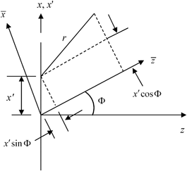
Fig. 3.3
Rotated coordinates for defining the wave field of a linearly phased element

(3.8)
which can be expanded in the exact form

(3.9)
We are using rotated coordinates since in this section we will examine delay laws that steer the beam produced by a large element to directions away from the z-axis. In this case the beam will be best described in a rotated set of coordinates. If the steered beam is well-collimated in the  -direction, then it makes sense to apply the paraxial approximation to the radius r in that direction. In our expansion of the radius in Eq. (3.2), we used the expansion
  . If we write Eq. (3.9) in a similar form as
  , where
 -direction, then it makes sense to apply the paraxial approximation to the radius r in that direction. In our expansion of the radius in Eq. (3.2), we used the expansion
  . If we write Eq. (3.9) in a similar form as
  , where
(3.10)
the appearance of  in the numerator of the
  term means that if we expand r for
  and wish to keep all quantities to
 ![$$O[ {{({x}'/\bar{z})}^{2}} ]$$](/wp-content/uploads/2016/05/A314073_1_En_3_Chapter_IEq23.gif) we must also include the next term in the expansion, namely
we must also include the next term in the expansion, namely
 in the numerator of the
  term means that if we expand r for
  and wish to keep all quantities to
 ![$$O[ {{({x}'/\bar{z})}^{2}} ]$$](/wp-content/uploads/2016/05/A314073_1_En_3_Chapter_IEq23.gif) we must also include the next term in the expansion, namely
we must also include the next term in the expansion, namely
(3.11)
Using this expansion we obtain
![$$ r\cong \bar{z}\left[ 1+\frac{{{({x}')}^{2}}{{\cos }^{2}}\Phi }{2{{{\bar{z}}}^{2}}}+\frac{{{{\bar{x}}}^{2}}}{2{{{\bar{z}}}^{2}}}-\frac{\bar{x}{x}'\cos \Phi }{{{{\bar{z}}}^{2}}}-\frac{{x}'\sin \Phi }{{\bar{z}}} \right] $$](/wp-content/uploads/2016/05/A314073_1_En_3_Chapter_Equ12.gif)
(3.12)
which, when placed into Eq. (3.7) gives
![$$ \begin{aligned} p(\mathbf{x},\omega )&=\rho c\sqrt{\frac{k}{2\pi i\bar{z}}}\exp (ik\bar{z}) \\ & \cdot \int\limits_{-b}^{+b}{{{{\bar{v}}}_{z}}({x}',0,\omega )\exp \left\{ ik\left[ \frac{{{({x}'\cos \Phi -\bar{x})}^{2}}}{2\bar{z}}-{x}'\sin \Phi\right] \right\}d{x}'}.\end{aligned} $$](/wp-content/uploads/2016/05/A314073_1_En_3_Chapter_Equ13.gif)
(3.13)
Now, suppose the velocity on the face of the element has a constant amplitude,  , (piston behavior) but also with a phase term, i.e.
 , (piston behavior) but also with a phase term, i.e.
(3.14)
which corresponds to specifying a continuous, linearly varying time delay,  , over the face of the transducer element. Then we see that this phase term just cancels the one appearing in Eq. (3.13) and if we write that equation in terms of the variable
  , it becomes
 , over the face of the transducer element. Then we see that this phase term just cancels the one appearing in Eq. (3.13) and if we write that equation in terms of the variable
  , it becomes
![$$ p(\mathbf{x},\omega )=\frac{\rho c{{v}_{0}}}{\cos \Phi }\sqrt{\frac{k}{2\pi i\bar{z}}}\exp (ik\bar{z})\int\limits_{-b\cos \Phi }^{+b\cos \Phi }{\exp \left\{ ik\left[ \frac{{{(w-\bar{x})}^{2}}}{2\bar{z}} \right] \right\}dw}. $$](/wp-content/uploads/2016/05/A314073_1_En_3_Chapter_Equ15.gif)
(3.15)
The integral of Eq. (3.15) is of the same form as Eq. (3.3) so that we can follow the same steps used with that equation to write the pressure in terms of Fresnel integrals. The result, in the  coordinates, is explicitly:
 coordinates, is explicitly:
![$$ p(\bar{x},\bar{z},\omega )=\frac{\rho c{{v}_{0}}}{\cos \Phi }\sqrt{\frac{1}{2i}}\exp (ik\bar{z})\left[ F\left( \sqrt{\frac{k}{\pi \bar{z}}}(\bar{x}+b\cos \Phi ) \right)-F\left( \sqrt{\frac{k}{\pi \bar{z}}(\bar{x}-b\cos \Phi )} \right) \right]. $$](/wp-content/uploads/2016/05/A314073_1_En_3_Chapter_Equ16.gif)
(3.16)
If we compare Eq. (3.16) with Eq. (3.5) for the radiated field of a piston transducer, we see that the linear time delay law  produces a wave field of a “virtual” rotated transducer (Fig. 3.4) of length
  having a driving velocity of
  on its face.
 produces a wave field of a “virtual” rotated transducer (Fig. 3.4) of length
  having a driving velocity of
  on its face.
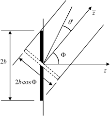
Fig. 3.4
The rotated “virtual” transducer that generates the same wave field as a linearly phased element in the paraxial approximation
Thus, a spatially varying time delay on the face of the element that is linear (in  ) of the form
 ) of the form
(3.17)
steers the entire beam of the transducer along an axis that makes an angle,  , with respect to the z-axis. We should note that the “delay” law of Eq. (3.17) actually involves both delays (for
  positive) and advances (for
  negative). It is not physically possible to generate time advances in a phased array but by simply adding a positive, constant term to Eq. (3.17) one can generate a steering law consisting of delays only.
 , with respect to the z-axis. We should note that the “delay” law of Eq. (3.17) actually involves both delays (for
  positive) and advances (for
  negative). It is not physically possible to generate time advances in a phased array but by simply adding a positive, constant term to Eq. (3.17) one can generate a steering law consisting of delays only.
3.2.2 Steering in the Far Field
In Chap. 2 we obtained explicit results for the wave field in the far field of the element. We found the far field pressure was given by Eq. (2.35):

(3.18)
where

(3.19)
and  . If we apply the velocity of Eq. (3.14) to the face of the element, then the integral yields instead
 . If we apply the velocity of Eq. (3.14) to the face of the element, then the integral yields instead
![$$ V({{k}_{x}})=2{{v}_{0}}(\omega )\frac{\sin [ ({{k}_{x}}-k\sin \Phi )b ]}{({{k}_{x}}-k\sin \Phi )}, $$](/wp-content/uploads/2016/05/A314073_1_En_3_Chapter_Equ20.gif)
(3.20)
which shows that the far field pressure is
![$$ p(\mathbf{x},\omega )=\rho c{{v}_{0}}(\omega )\sqrt{\frac{2}{\pi i}}(kb)\frac{\sin [ ({{k}_{x}}-k\sin \Phi )b ]}{({{k}_{x}}-k\sin \Phi )b}\frac{\exp (ik{{r}_{0}})}{\sqrt{k{{r}_{0}}}} $$](/wp-content/uploads/2016/05/A314073_1_En_3_Chapter_Equ21.gif)
(3.21)
and the directivity of the element is now
![$$ {{D}_{b}}(\theta )=\frac{\sin [ kb(\sin \theta -\sin \Phi ) ]}{kb(\sin \theta -\sin \Phi )}. $$](/wp-content/uploads/2016/05/A314073_1_En_3_Chapter_Equ22.gif)
(3.22)
Since the directivity is governed by the sinc function,  , which has its maximum at x = 0, it is clear from Eq. (3.22) that that maximum (and hence the entire directivity function) has been steered to the
  direction by the linear phasing of the element.
 , which has its maximum at x = 0, it is clear from Eq. (3.22) that that maximum (and hence the entire directivity function) has been steered to the
  direction by the linear phasing of the element.
We can also relate these results with those of the last section by noting that in the rotated  coordinates we have wave numbers
  where
where  . But in the paraxial approximation
  so that
  and we can write Eq. (3.21) in the rotated coordinates as
 coordinates we have wave numbers
  where
where  . But in the paraxial approximation
  so that
  and we can write Eq. (3.21) in the rotated coordinates as
![$$ p(\mathbf{x},\omega )=\rho c\frac{{{v}_{0}}(\omega )}{\cos \Phi }\sqrt{\frac{2}{\pi i}}(kb\cos \Phi )\frac{\sin [ {{k}_{{\bar{x}}}}b\cos \Phi]}{{{k}_{{\bar{x}}}}b\cos \Phi }\frac{\exp (ik{{r}_{0}})}{\sqrt{k{{r}_{0}}}}, $$](/wp-content/uploads/2016/05/A314073_1_En_3_Chapter_Equ23.gif)
(3.23)
where  and
and  is measured from the
  -axis (Fig. 3.4). Comparing Equation (3.23) with the far field expression of Eq. (2.38) for an element without steering shows that in the paraxial approximation the far field response of the linear phased element in the rotated coordinates is identical to the far field from a virtual transducer of length
  which has a velocity
  acting on its face, which is consistent with our results in the previous section.
 and
and  is measured from the
  -axis (Fig. 3.4). Comparing Equation (3.23) with the far field expression of Eq. (2.38) for an element without steering shows that in the paraxial approximation the far field response of the linear phased element in the rotated coordinates is identical to the far field from a virtual transducer of length
  which has a velocity
  acting on its face, which is consistent with our results in the previous section.
3.2.3 Beam Focusing
For a large single element piston transducer, one way that focusing can be achieved in two dimensions is to place a set of uniform normal velocity sources on a circular aperture of radius  instead of a straight aperture, as shown in Fig. 3.5. This is the 2-D equivalent of the O’Neil model for a spherically focused transducer [3], [Schmerr]. The same focusing effect, however, can also be simulated by applying the uniform sources over the straight aperture (located at z = 0) and changing the time of arrival of the waves from different locations on the transducer face so that they are all in phase on the circular aperture, just as they are in the configuration of Fig. 3.5. First, consider a wave that has traveled from a point
  at z = 0 to the location of the geometrical focus on the z-axis (see Fig. 3.6). Then consider the same wave traveling on the same path from the circular aperture to the focus. The time difference between these two cases is simply
 instead of a straight aperture, as shown in Fig. 3.5. This is the 2-D equivalent of the O’Neil model for a spherically focused transducer [3], [Schmerr]. The same focusing effect, however, can also be simulated by applying the uniform sources over the straight aperture (located at z = 0) and changing the time of arrival of the waves from different locations on the transducer face so that they are all in phase on the circular aperture, just as they are in the configuration of Fig. 3.5. First, consider a wave that has traveled from a point
  at z = 0 to the location of the geometrical focus on the z-axis (see Fig. 3.6). Then consider the same wave traveling on the same path from the circular aperture to the focus. The time difference between these two cases is simply
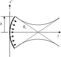
Fig. 3.5
A focused piston transducer consisting of a set of uniform velocity sources on a circular line of radius 

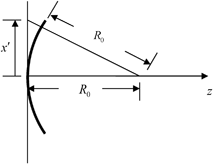
Fig. 3.6
Geometry for defining the phasing needed to focus the waves from an unfocused element to a point on the z-axis

(3.24)
In the paraxial approximation  this time difference is approximately
 this time difference is approximately
![$$ \begin{aligned} \Delta t({x}')&=\frac{{{R}_{0}}\left[ \sqrt{1+{{({x}'/{{R}_{0}})}^{2}}}-1 \right]}{c} \\ & \cong \frac{{{R}_{0}}\left[ 1+{{({x}'/{{R}_{0}})}^{2}}/2+\ldots -1 \right]}{c} \\ & =\frac{{{({x}')}^{2}}}{2{{R}_{0}}c},\end{aligned} $$](/wp-content/uploads/2016/05/A314073_1_En_3_Chapter_Equ25.gif)
(3.25)
corresponding to a propagation phase delay term given by
![$$ \exp [ i\omega \Delta t ]=\exp \left[ ik\frac{{{({x}')}^{2}}}{2{{R}_{0}}} \right]. $$](/wp-content/uploads/2016/05/A314073_1_En_3_Chapter_Equ26.gif)
(3.26)
Thus, if on the planar aperture we specify a velocity field given by
![$$ {{v}_{z}}({x}',0,\omega )=\left\{ \begin{matrix} {{v}_{0}}(\omega )\exp \left[{-}ik\frac{{{({x}')}^{2}}}{2{{R}_{0}}} \right] & \begin{array}{l} -b\le {x}'\le b \\\\ \end{array}\\ 0 & otherwise\\\end{matrix} \right., $$](/wp-content/uploads/2016/05/A314073_1_En_3_Chapter_Equ27.gif)
(3.27)
we will produce the same cylindrical focusing effect of the circular aperture. Note that the phase term in Eq. (3.27) has a negative sign since for all  on the plane z = 0 we need to advance the arrival time of the waves relative to the arrival at the focus from the point
  to have them arrive in phase on the circular element. Thus, our “delay” law is the negative of the time differences appearing in Eqs. (3.25) and (3.26), i.e.
 on the plane z = 0 we need to advance the arrival time of the waves relative to the arrival at the focus from the point
  to have them arrive in phase on the circular element. Thus, our “delay” law is the negative of the time differences appearing in Eqs. (3.25) and (3.26), i.e.
(3.28)
Again, in this form we do not have a physically possible delay law but by simply adding a constant delay term to Eq. (3.28) we can turn these advances into a law with delays only.
Now, consider the wave field of a large element where the velocity on the element face is given by Eq. (3.27). Then from Eq. (3.7) the pressure is given by
![$$ p(\mathbf{x},\omega )=\rho c{{v}_{0}}(\omega )\sqrt{\frac{k}{2\pi i}}\int\limits_{-b}^{+b}{\exp \left[{-}ik\frac{{{({x}')}^{2}}}{2{{R}_{0}}} \right]\frac{\exp (ikr)}{\sqrt{r}}d{x}'}. $$](/wp-content/uploads/2016/05/A314073_1_En_3_Chapter_Equ29.gif)
(3.29)
In the paraxial approximation (see Eq. (3.2)) then we have
![$$ p(\mathbf{x},\omega )=\rho c{{v}_{0}}(\omega )\sqrt{\frac{k}{2\pi i}}\frac{\exp (ikz)}{\sqrt{z}}\exp \left( ik\frac{{{x}^{2}}}{2z} \right)\int\limits_{-b}^{+b}{\exp \left\{ \frac{ik}{2z}[ {{u}_{0}}{{({x}')}^{2}}-2x{x}' ] \right\}d{x}'}, $$](/wp-content/uploads/2016/05/A314073_1_En_3_Chapter_Equ30.gif)
(3.30)
where

(3.31)
But we can “complete the square” in the phase term appearing in the integrand of Eq. (3.30) and rewrite that equation as

(3.32)

(3.33)
which can again be expressed as two Fresnel integrals:
![$$ \begin{aligned} p(\mathbf{x},\omega )&=\frac{\rho c{{v}_{0}}(\omega )\exp (ikz)}{\sqrt{\left| {{u}_{0}} \right|}}\sqrt{\frac{1}{2i}} \\ & \cdot \exp \left({-}ik\frac{{{x}^{2}}}{2\left| {{u}_{0}} \right|{{R}_{0}}} \right)\left\{ F\left[ \sqrt{\frac{k\left| {{u}_{0}} \right|}{\pi z}}\left( \frac{x}{\left| {{u}_{0}} \right|}+b \right) \right]-F\left[ \sqrt{\frac{k\left| {{u}_{0}} \right|}{\pi z}}\left( \frac{x}{\left| {{u}_{0}} \right|}-b \right) \right] \right\}\end{aligned} $$](/wp-content/uploads/2016/05/A314073_1_En_3_Chapter_Equ34.gif)
(3.34)
and we have let  to emphasize that it is positive.
 to emphasize that it is positive.
![$$ \begin{aligned} p(\mathbf{x},\omega )&=\frac{\rho c{{v}_{0}}(\omega )\exp (ikz)}{\sqrt{\left| {{u}_{0}} \right|}}\sqrt{\frac{1}{2i}}\exp {{\left({-}ik\frac{{{x}^{2}}}{2\left| {{u}_{0}} \right|{{R}_{0}}} \right)}^{*}} \\ & \cdot {{\left\{ F\left[ \sqrt{\frac{k\left| {{u}_{0}} \right|}{\pi z}}\left( \frac{x}{\left| {{u}_{0}} \right|}+b \right) \right]-F\left[ \sqrt{\frac{k\left| {{u}_{0}} \right|}{\pi z}}\left( \frac{x}{\left| {{u}_{0}} \right|}-b \right) \right] \right\}}^{*}}.\end{aligned} $$](/wp-content/uploads/2016/05/A314073_1_En_3_Chapter_Equ35.gif)
(3.35)
The  here indicates the complex conjugate.
 here indicates the complex conjugate.
Now, consider the on-axis response of the element in the paraxial approximation. This response can be obtained from Eqs. (3.34) and (3.35) by setting x = 0 to obtain

(3.37)
Stay updated, free articles. Join our Telegram channel

Full access? Get Clinical Tree


