5.
Krebs-Ringer Carbicarb buffer (KRC): 2.0 mM CaCl2, 11.0 mM d-glucose, 4.7 mM KCl, 4.0 mM MgSO4, 118 mM NaCl, 12.5 mM Na2CO3, 12.5 mM NaHCO3, pH = 7.35–7.4, osmolality = 300–330 mmol/kg (see Note 4).
6.
Fixative: 2.0% formaldehyde, 2.5% glutaraldehyde, 2 mM CaCl2, 4 mM MgSO4, 100 mM sodium cacodylate, pH = 7.35 (aldehydes and sodium cacodylate are obtained from Ladd Research; see Note 5).
7.
Vacuum filter system (pore size = 0.22 μm) to filter KRC and fixative.
2.2 Tissue Processing
1.
Vibrating blade microtome.
2.
24-well plates.
3.
0.1 M phosphate buffer, pH 7.4.
4.
Dissecting microscope.
5.
Small dissecting knife, ∼4 mm cutting edge (Fine Science Tools).
6.
0.1 M sodium cacodylate buffer, pH 7.4.
7.
Agarose: 7% in purified water.
8.
Laboratory microwave oven with vacuum chamber and cooling stage (Ted Pella): prior to tissue processing, the magnetron needs to be warmed up by running it for 2 min at 175 W.
9.
Tissue processing basket (Ted Pella).
10.
Reduced osmium: 1% osmium tetroxide (see Note 6) and 1.5% potassium ferrocyanide [K4Fe(CN)6⋅3H2O] in sodium cacodylate buffer.
11.
1% Osmium tetroxide in sodium cacodylate buffer (see Note 6).
12.
Uranyl acetate (ACS reagent grade).
13.
Ethanol (see Note 7).
14.
Propylene oxide.
15.
LX-112 epoxy resin embedding kit (Ladd Research).
16.
Rotator.
17.
Chien embedding mold (Electron Microscopy Sciences, Polysciences, or Ted Pella).
18.
Laboratory oven.
2.3 Ultramicrotomy and Post-section Staining
1.
SynapTek™ beryllium-copper slot grids, slot size = 1 mm × 2 mm or 0.5 mm × 2 mm (Ted Pella or Electron Microscopy Sciences).
2.
Pioloform® F (Ted Pella): 0.7% solution in high-purity chloroform.
3.
Supplies for casting Pioloform films, including a film casting device (Electron Microscopy Sciences), Ross optical lens tissue paper, 70% ethanol, Alconox® (saturated aqueous solution filtered and diluted to ∼20%), and a large glass container (to contain water on which Pioloform films are floated).
4.
Ultramicrotome (Leica Microsystems), placed in a Plexiglas enclosure on an air table in a dedicated room (Fig. 2g).
Fig. 2.
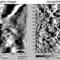
(a) Dorsal view of a perfusion-fixed adult rat brain. Dotted black line indicates an approximate location from which the slice shown in b and b′ was taken on a vibrating blade microtome. (b) A parasagittal slice of the hippocampus. Area CA1 and the dentate gyrus (DG) are indicated. (b′) The same slice as in b, with a superimposed image of the dentate tissue embedded in the epoxy block shown in c. (c) An epoxy block containing the dentate tissue dissected from the slice shown in b and b′. The Chien embedding mold was used so that the tissue can be cut from two faces of the block (C with dotted line = “cross-section face”; L with solid line = “longitudinal face”). (c′) A diagram indicating the orientation of the tissue in the block shown in c. The “cross-section face” (C) is parallel to the granule cell layer (gray spheres), and dendrites (gray curved lines in the molecular layer) of these cells are cut in cross section in this plane. The “longitudinal face” (L) is perpendicular to the cell layer and the cross-section face, and therefore the dendrites are cut longitudinally in this plane. In this example, serial sections are cut from the cross-section face at 125 μm from the top of the granule cell layer (i.e., middle molecular layer). (d) An electron micrograph of a test-thin section cut from the longitudinal face of the block shown in c. This image is used to determine how much of the tissue must be trimmed to reach the target location on the cross-section face (i.e., 517 − 125 μm = 392 μm to trim). The rectangle with dotted line indicates the area imaged in E after trimming. “Hash” corresponds to the location of capillary seen in E. Note that flaws in the thin section or Pioloform film (e.g., folds) cannot be avoided in sections of this size (also see e), but they are minimized in serial sections cut from a much smaller block face (see h). (e) An electron micrograph of another test-thin section, taken after trimming to the target location. The target (125 μm) will be well within a series of 200 serial sections (spanning about 9 μm), so the final block face is trimmed at this point. (f) A diagram showing the final block face (gray trapezoid area) trimmed on the cross-section face of the block. The asterisk (also in f′ and h) indicates the “reference corner”: the edge extending into tissue from this corner is perpendicular to the block face, and therefore remains constant throughout the series. (f′): The top-down view of the longitudinal face of the block in f, depicting the method for trimming the top and bottom edges of the block face. After the bottom edge is trimmed with a 20° slope, the knife is turned 20° to the right, so that the top edge is trimmed to become perpendicular to the block face. (g) In a dedicated room, the ultramicrotome (u) is placed in a Plexiglas enclosure (e) on an air table (t). A video camera is fitted to the ultramicrotome so that serial sectioning can be monitored with a video display (d) after closing the glass front window of the enclosure. (h) A low-magnification SEM image of a segment of serial sections on a single Pioloform-coated grid. Large capillaries are evident in each section. The reference corner (indicated by asterisk) is used to navigate to the ROI during imaging (see Fig. 3d).
5.
Diamond trim knife (DiATOME cryotrim 20).
6.
Diamond thin-sectioning knife (DiATOME ultra 35).
7.
Supplies for manipulating and picking up serial sections such as eyelash, forceps, and grid box.
8.
Grid staining dish (with lid): 55 mm glass Petri dish filled with melted dental wax. Indentations are made on the wax surface with a razor blade so that grids can be inserted vertically.
9.
Uranyl acetate: Saturated aqueous solution. Add 6.25 g of uranyl acetate to 100 ml of purified water and sonicate for up to 1 h. Store at 4°C.
10.
Reynolds’ lead citrate stain (36): In purified water boiled to expel CO2, completely dissolve lead nitrate (Ladd Research) for the final concentration of 2.66%, then sodium citrate (3.52% final). The solution will turn milky white. After letting stand for 30 min with occasional mixing, add fresh aqueous sodium hydroxide (0.16 N final) (see Note 8). To avoid exposure to air, store in 10 ml syringes with syringe filer and hypodermic needle stuck on a rubber stopper at 4°C.
11.
Sodium hydroxide: some pellets and 0.02 N aqueous solution.
2.4 Serial Section Imaging and Analysis
1.
Zeiss FE SEM with a retractable transmitted electron detector and a specimen holder for TEM grids: a SUPRA® 40 in this configuration is used in our laboratory, and the following descriptions of the microscope operation will be based on this model. Other current models of Zeiss FE SEM can also be configured in the same manner, and their operations are essentially identical to ours. At the time of this writing, Zeiss is the sole source of the FE SEM system designed for high-resolution large-field STEM imaging of biological samples as described in this chapter.
2.
Zeiss ATLAS™ system integrated with the SEM for semi-automated large field imaging.
3.
Grating replica grid for calibration (Electron Microscopy Sciences).
4.
Workstation running FIJI for image alignment and other preprocessing (freely available at: http://fiji.sc/) (see Note 9). A workstation with multiple CPU cores (e.g., ours has 16 cores at 2 GHz) with 64 GB of RAM and 2 TB of hard drives set up in RAID should be sufficiently powerful to handle series of large serial images (∼500 MB per image).
5.
Workstation running RECONSTRUCT™ (version 1.1.0.0; 32-bit) for image analysis and 3D reconstruction (freely available at: http://synapses.clm.utexas.edu/) (26).
3 Methods
3.1 Perfusion-Fixation (See Notes 10 and 11)
This perfusion-fixation procedure is performed best with two persons, one acting as the surgeon (i.e., performing tracheotomy and inserting the perfusion needle) and the other as assistant (i.e., adjusting the delivery pressure, switching from KRC to fixative, etc.). A simplified schematic of our perfusion apparatus is illustrated in Fig. 1. A hand air pump (a modified sphygmomanometer) is used to apply pressure to drive the perfusates (KRC and fixative), which are warmed in a water bath so that they are at 37°C at the tip of perfusion needle (13-gauge). KRC is bubbled with O2/CO2 (95%/5%) for at least 30 min prior to start of perfusion. O2/CO2 is also used to drive an anesthetic vaporizer, which is connected to a nose cone (used until tracheotomy is done; step 3 below) and a ventilator (for artificial respiration). The ventilator is in turn connected to an endotracheal tube, which is made with tubing attached to a blunt 16-gauge needle (1 cm long).
1.
The vaporizer is set at 5% anesthetic with the flow at 400 ccm. The ventilator should be running at 120 strokes/min with a tidal volume of 1.5 cc.
2.
Anesthesia is induced in a large desiccator jar with a wad of several small Kimwipes. Five minutes prior to placing the animal, add ∼1.5 ml of halothane or isoflurane to the Kimwipes below the perforated plate and put the lid on the desiccator. Make sure the animal does not come in contact with liquid halothane or isoflurane. Test the animal’s anesthesia level with a toe pinch. A sufficiently anesthetized animal will not respond. After attaching the nose cone, the animal is secured with pins onto a Styrofoam board in the dissection tray.
3.
To establish artificial respiration, surgically expose the trachea via a chin-to-sternum incision, partially cut across the trachea, and insert the endotracheal tube into the trachea. A piece of suture is tied around the trachea to secure the inserted tube. The nose cone can be removed at this point.
4.
After opening the thoracic cavity and exposing the heart, the right atrium is cut and perfusion needle is inserted into the left ventricle to start perfusion with warm oxygenated KRC delivered at 80 mmHg for a few seconds.
5.
The perfusate is switched to the fixative solution, and the pressure is increased to 180 mmHg. The chin is cut to see if the fixative drips out, which confirms that it is delivered to the head (see Note 12). After 10 min of perfusion with fixative, the pressure is reduced to 40–80 mmHg, or to the point where fixative is very slowly dripping from the cut chin of the animal. At the end of perfusion, each animal should have received 1,800–2,000 ml of fixative over the course of about 60 min (see Note 13).
6.
The brain is allowed to remain undisturbed in the cranium for at least 1 h (but not more than a few hours). Then it is carefully dissected from the cranium (Fig. 2a) and soaked in the same fixative solution overnight at RT (see Notes 14 and 15).
3.2 Tissue Processing (See Notes 10 and 11)
1.
The fixed brain is transferred to phosphate buffer and sliced with a vibrating blade microtome. We typically take parasagittal slices at the thickness of 70 μm. The slices are sequentially collected and stored in 24-well plates containing the fixative at RT until EM processing (see Notes 16 and 17).
2.
The 70 μm thick slice is transferred to sodium cacodylate buffer, and a piece of tissue containing the area of interest (the hippocampal dentate gyrus in this example; Fig. 2b and b′) is dissected out with a small knife under a dissecting microscope.
3.
The tissue is embedded into 7% agarose between glass microscope slides (with thickness of one #1 cover glass) to protect it during the subsequent processing. A block of agarose containing the tissue is cut out and placed in a processing basket filled with sodium cacodylate buffer.
4.
After rinses in the buffer, the tissue is osmicated in two steps: (1) Reduced osmium solution for 5 min, followed by the buffer rinses; and (2) 1% osmium tetroxide solution for two 3-min cycles (1 min ON → 1 min OFF → 1 min ON) at 175 W under vacuum in a laboratory microwave oven. This is followed by rinses in the buffer and then in purified water.
5.
The osmicated tissue is then dehydrated through ascending concentrations of ethanol and stained en bloc with 1% uranyl acetate. After it is placed in 50% ethanol for 5 min, transfer the tissue into 50% ethanol containing 1% uranyl acetate, then apply 40 s of microwave (at 250 W without vacuum). Repeat the same microwave procedure for the 70, 90, and 100% ethanol solutions (each containing 1% uranyl acetate) and again for 100% ethanol (without uranyl acetate).
6.
The tissue is placed on a rotator in mixtures of ethanol and propylene oxide (1:1 and then 1:2, 10 min each, followed by two exchanges of 100% propylene oxide over 30 min) and infiltrated with LX-112 epoxy resin (1 h with a mixture of 1:1 = propylene oxide:resin, then overnight with 1:2 = propylene oxide:resin, followed by three exchanges of 100% resin over 3 h).
7.
The tissue is arranged into the Chien mold such that one edge is parallel to the granule cell layer (“cross-section face” or C in Fig. 2c and c′) and the other edge perpendicular to it (“longitudinal face” or L in Fig. 2c and c′). This arrangement allows for subsequent ultrathin sectioning of the tissue from two directions: one with longitudinally sectioned dendrites and the other at precise locations in the field with cross-sectioned dendrites (see Subheading 3.3).
8.
The epoxy-embedded tissue is cured in a laboratory oven at 60°C for 48 h (see Note 18).
3.3 Ultramicrotomy and Post-section Staining (see Notes 10 and 11)
We typically cut 200–300 serial sections at 45 nm thickness from a target location (35). However, there is no particular limit to the number of serial sections that can be obtained and imaged other than the skill of the operator and time (see Notes 19 and 20). Here, an example illustrated in Fig. 2 shows a strategy to target the middle molecular layer of the hippocampal dentate gyrus at 125 μm from the top of the granule cell layer, such that the granule cell dendrites are cut in the cross-section plane. This targeting strategy can easily be adopted to collect serial sections from other brain areas.
1.
On an ultramicrotome, the block of epoxy-embedded tissue is secured on a vise-style chuck and trimmed perpendicular to the granule cell layer to expose the tissue on the “longitudinal face” (i.e., along or parallel to the dendritic arbor traversing the molecular layer; L in Fig. 2c and c′). An ultrathin section is collected and used to locate the target area for serial-sectioning (Fig. 2d). Tissue quality is also evaluated in this test-thin section in the electron microscope.
2.
Turn the block 90° in the chuck (i.e., parallel to the granule cell layer), and trim it on the “cross-section face” (C in Fig. 2c and c′) to the target region of interest. Cut an ultrathin section of the “cross-section face,” which is used to place the final block face (step 4; Fig. 2f). Also cut another ultrathin section from the “longitudinal face” to confirm that you have reached the target location (Fig. 2e). It may be necessary to repeat steps 1 and 2 before the block face reaches the target.
3.
 Introduction: Nanoimaging Techniques in Biology
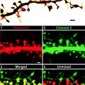 Two-Color STED Imaging of Synapses in Living Brain Slices
 Secondary Ion Mass Spectrometry Imaging of Biological Membranes at High Spatial Resolution
 High Data Output Method for 3-D Correlative Light-Electron Microscopy Using Ultrathin Cryosections
 Functional AFM Imaging of Cellular Membranes Using Functionalized Tips
 Nanoimaging Cells Using Soft X-Ray Tomography


Pioloform-coated slot grids are prepared the day before cutting serial sections (see Note 21). Glass microscope slides are cleaned with 70% ethanol and purified water, then coated with 20% saturated aqueous solution of Alconox detergent. The slides are scrubbed dry with Ross lens tissue after each step of cleaning and coating. Using a clean film casting device, Pioloform film is casted onto the slides from a 0.7% chloroform solution of Pioloform F (see Note 22). After being dried in a jar with desiccant, the film is floated on a surface of still water, and slot grids are placed on the film showing a uniform silver interference color (see Note 23). Secure the grids onto the film by tapping them on the edges with forceps, pick up onto Parafilm-wrapped glass slides, and air-dry overnight in a petri dish (see Note 20). The quality of the Pioloform film should be checked under EM.
Related posts:
Introduction: Nanoimaging Techniques in Biology
Two-Color STED Imaging of Synapses in Living Brain Slices
Secondary Ion Mass Spectrometry Imaging of Biological Membranes at High Spatial Resolution
High Data Output Method for 3-D Correlative Light-Electron Microscopy Using Ultrathin Cryosections
Functional AFM Imaging of Cellular Membranes Using Functionalized Tips
Nanoimaging Cells Using Soft X-Ray Tomography
Stay updated, free articles. Join our Telegram channel
Full access? Get Clinical Tree
