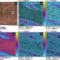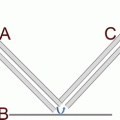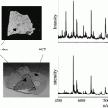
Fig. 1
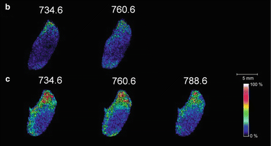
(a) Schematic of the laser ablation sample transfer system for MALDI imaging. MALDI images of mouse brain sections prepared by IR laser ablation transfer to (b) matrix-pre-coated target and (c) target with subsequent matrix addition (reprinted with permission from Reference 51; Copyright 2012 American Chemical Society)
After the material is transferred from the sample slide to the slide, NALDI, or MALDI target, the latter is mounded in a slide adaptor and analyzed using MALDI mass spectrometry. Images are constructed from the mass spectra from using imaging software. For multiple images from a single sample slide using different target slides, a target slide is replaced with a new target slide after scanning the tissue with the IR laser. The sample and new target slides are mounted on the XY stage and scanned again under the IR laser. For concentrating ablated material from large area of tissue onto a single spot on the target slide, the sample slide is moved under the laser beam and the target slide is held in place to capture the material in one spot.
To demonstrate the spatial resolution that can be obtained using laser ablation sample transfer, a peptide mass standard was laser ablation transferred from a sample target deposit to a set of lines on the target slide and imaged. For this experiment, a 1 mM solution of the peptide angiotensin II was spray deposited onto a microscope slide. After air-drying, a glycerol solution was sprayed on the deposit to wet it. The slide was placed in the target with a 70 μm spacing and irradiated at 3 kJ/m2 laser fluence. The gaps between laser-ablated lines were 1 mm, 800 μm, 600 μm, 400 μm, and 300 μm. From this image, it can be seen that the minimum distinguishable spacing of the transferred lines on the target is 400 μm.
3.1 Preparation of Sample Slides
1.
Transfer a mouse brain onto a cooled sample stage (−20 °C) of a cryostat.
2.
Obtain a mouse brain section of 10 μm thickness.
3.
Thaw-mount the tissue on a conductive side of ITO-coated microscope slide (sample slide). A multimeter can be used to determine which side is conductive.
4.
Store the tissue sample slides at −80 °C before using.
3.2 Preparation of Target Slides
Before preparation of a target slide, optimize the time for spraying and drying, and the distance between the nozzle and the sample to make a homogenous coating on the target (see Notes 1 – 3 ).
1.
Use a TLC nebulizer with nitrogen gas to spray the nitrocellulose or matrix solution.
2.
Mount an ITO-coated microscope slide perpendicularly in a hood.
3.
Add the prepared nitrocellulose solution into the TLC sprayer.
4.
Set the distance between the slide and sprayer to about 30 cm.
5.
Spray the ITO glass slide for 20 s and dry for 2 min.
6.
Repeat step 5 nine more times (ten times in all).
7.
For a matrix-pre-coated target, spray a matrix solution onto the nitrocellulose-coated slide for 20 s and dry for 2 min.
8.
Repeat step 7 nine more times (ten times in all).
3.3 Laser Ablation Sample Transfer for MALDI Imaging
1.
Optimize the gap between the sample and target slides and optimize the laser pulse energy. To optimize the gap and laser energy, a 1 mM solution of angiotensin II is sprayed on a sample slide. After air-drying, a glycerol solution is sprayed on the sample slide to assist the IR laser ablation. The sample slide faces toward the target slide, and the gap between the slide and target is adjusted using different thicknesses of adhesive tape. The slides with different gaps are irradiated at a single spot at different laser energies. After transfer of material from the sample slide, the target slides are spray coated with CHCA matrix and imaged using MALDI. For example, Fig. 2 shows MALDI images of peptide spots transferred by IR laser ablation at different IR laser fluences and different distances between the sample and target slide. At a spacing of 70 μm and 3 kJ/m2 laser fluence, a small peptide spot size is observed although less material is transferred (see Note 4 ).
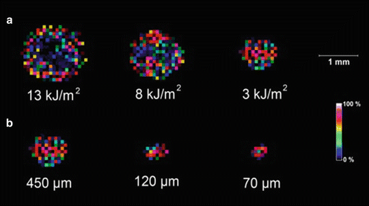

Fig. 2
MALDI image of peptide spots transferred by IR laser ablation (a) at the indicated laser fluences and at a spacing of 450 μm and (b) at the indicated distances and at a laser fluence of 3 kJ/m2 (reprinted with permission from Reference 51; Copyright 2012 American Chemical Society)
2.
Place sample slide face down against the target slide with a spacing of 70 μm.
3.
Mount the two slides on the translation stage.
4.
Use gold-coated first-surface mirrors and CaF2 lens to focus the mid-IR laser beam onto the sample at normal incidence in transmission mode (backside irradiation).
5.
Scan the sample and target slides under the IR laser beam to transfer material from the sample to target slides. The linear velocity of the stage is 30 μm/s, and a serpentine pattern with 20 μm raster line spacing is traced. The laser wavelength is 3 μm and the number of laser shot is 200 at 20 Hz repetition rate (see Note 5 ).
6.
Remove the target slide and mount it in the adaptor. If the target slide is not pre-coated with MALDI matrix (target slide coated with nitrocellulose), apply matrix to the transferred material using the TLC sprayer as described in Subheading 3.2 (steps 7 and 8) before MALDI imaging.
3.4 Multiple Tissue Transfers
1.
After first ablating a tissue sample to transfer material to a target slide as described in Subheading 3.3, the target slide is replaced with a new target slide (coated with matrix or a NALDI target).
2.
Place the sample side with the first scanned tissue sample on the new target slide, scan again under the IR laser beam, and run MALDI from the target slide.
3.5 Area to Spot Transfer
1.
Mount a sample side on translation stage.
3.
Set the distance between the sample side and the target slide to 100 μm using the z-axis (see Note 7 ).
4.
Scan the sample under the IR laser beam to transfer material from an area of the tissue to a spot on the target slide.
5.
Add 2 μL of DHB matrix to the target and perform MALDI.
3.6 MALDI Imaging from a Sample Slide
1.
Mix equal volumes of a peptide standard solution with a CHCA matrix solution.
2.
Apply 1 μL of the solution to an ITO glass slide and dry at room temperature for MS.
3.
Mount a sample slide and the peptide standard slide in slide adapter.
4.
Insert the slide adapter into a MALDI mass spectrometer.
5.
Perform mass calibration using the peptide standard.
6.
After mass calibration, start the MS imaging run to scan the tissue sample and collect MALDI mass spectra.
7.
After collecting mass spectra, reconstruct MALDI images.
4 Notes
1.
The spray-coating step creates a uniform nitrocellulose/matrix layer on the surface. Smaller distances between the sprayer and the target slide and longer spraying times can result in overwetting the slide and an inhomogeneous layer.
2.
The water content in the tissue sample is a critical factor for mid-IR laser ablation sample transfer. Therefore, it is important to prevent the tissue from drying.
3.
Before mounting the slides on the translation stage for material transfer from sample slide to target slide, the area of the tissue sample should be marked on the back of the target slide around the tissue area. The mark is useful for finding the transferred tissue area when running MALDI imaging.
4.
At greater distances between the slides, the size of the spot of transferred material is larger due to the radial dispersion of the plume of ablated material. At high laser fluencies, the spot size of the transferred material on the MALDI target is much larger than the IR laser spot size. In addition, a donut-shaped image is observed due to ablation of the transferred sample or due to hydrodynamic ejection of material, which can result in removal of material from the sides of the ablation crater [52].
5.
A large number of laser shots in the first laser ablation transfer can lead to low material transfer for the second image.
6.


Before mounting the target slide, mark the spot on the backside of a target at the point that the ablated material will be transferred. In this experiment, the transferred area on the target slide is small (less than 120 μm), and it can be difficult to locate the spot of transferred material. The marked spot on the target indicates the transferred material.
Stay updated, free articles. Join our Telegram channel

Full access? Get Clinical Tree


