Fig. 1.
Light sheet-based microscopy. The central concept in light sheet-based microscopy is to illuminate the specimen in a single plane with a thin sheet of laser light and to record the fluorescence emitted by fluorophores in this thin section with a camera-based detection system oriented at a right angle to the light sheet. The optical sub-systems for illumination and detection are decoupled, which allows using separate objectives optimized for low numerical aperture (NA) specimen illumination and high-NA fluorescence detection. The light sheet is typically generated by scanning a pencil beam through the sample or by focusing a Gaussian beam along one direction into a sheet, using a suitable optical element such as a cylindrical lens.
Here, we provide an overview of light sheet-based microscopy assays for in vitro and in vivo imaging of biological samples in cell biology and developmental biology. We focus in particular on cell extracts, soft gels, and large multicellular organisms. Since light sheet-based microscopy experiments typically yield large amounts of image data, we also describe computational tools for basic image processing and post-experiment data inspection.
2 Materials
2.1 Sample Preparation in Transparent Plastic Cylinders
1.
Transparent plastic foil (bioFOLIE 25, Greiner Bio-One GmbH, see Note 1).
A different type of plastic foil is also acceptable, as long as it has the following properties: refractive index matched to water (1.33), thickness of less than 50 μm, transparent, and nondisruptive to the imaging process.
2.
Glass capillaries (Brand GmbH & Co KG).
3.
Hot air welding apparatus (Unitherm K 5.8RS, Zinser Schweisstechnik GmbH).
2.2 Sample Embedding in Soft Agarose Gels
2.2.1 Specimen Embedding
1.
Low melting temperature agarose (SeaPlaque Agarose, Lonza).
2.
Glass capillaries (2.5 mm outer diameter, 2.0 mm inner diameter, 20 mm length).
3.
Heating block (e.g., Thermostat Plus, Eppendorf).
4.
Dissection microscope (e.g., SZX7 stereo microscope with SZX2-ILLT-1-5 LED illumination base, Olympus).
5.
Petri dishes (e.g., cell culture dish, 100 mm × 20 mm).
6.
Pipette and tips.
7.
Microscope slides (e.g., SuperFrost Plus, Fisherbrand).
8.
High-quality forceps (e.g., Dumont #5).
2.2.2 Drosophila Preparation and Live Imaging
1.
Drosophila food vials.
2.
Apple juice plates.
3.
Yeast paste.
4.
Drosophila mating cages.
5.
Sieve.
6.
Scalpels.
7.
Sodium hypochlorite solution (bleach, Sigma-Aldrich).
2.2.3 Zebrafish Preparation and Live Imaging
1.
E3 medium:
For 5 L 60× stock: 87.5 g of 5 mM NaCl, 3.8 g of 0.17 mM KCl, 14.5 g of CaCl2 × 2H2O, 24.5 g MgSO4 × 7H2O; set pH to 7.2 with NaOH; autoclave.
3.
Pronase (Sigma-Aldrich).
2.3 Light Sheet-Based Microscopy
We use scanned light sheet-based microscopes for live imaging (digital scanned light sheet microscopy, DSLM). Early implementations of fluorescence light sheet microscopy typically relied on stationary mechano-optics to create static laser light sheets for specimen illumination (4, 8, 9). This strategy is still used in many designs and is particularly useful when implementing miniaturized instruments (10, 11) or when performing high-speed 2D imaging, e.g., to record the beating heart in fish embryos (12). Scanned light sheet microscopy (5) introduced a new degree of freedom and enabled the implementation of advanced strategies to light sheet-based specimen illumination. In scanned light sheet microscopy, the specimen is illuminated from the side with a thin pencil beam that is rapidly scanned in one dimension to form a uniform laser light sheet. Using a two-axis scanner, one can furthermore quickly displace the entire light sheet and thereby perform 3D imaging without actually moving the specimen itself. Due to the intrinsic incoherence of the illumination process in scanned light sheet microscopy, light-scattering induced artifacts are greatly reduced if compared to imaging with static light sheets (13, 14). The scanned light sheet microscopy approach forms the basis for high-quality light sheet-based structured illumination (7), high-resolution imaging with “self-healing” Bessel beams (13, 15, 16) and efficient light sheet-based two-photon (2p) excitation (15, 17).
A basic DSLM set-up, such as the instrument described in (5), consists of six sub-systems: (1) a light source, (2) a beam shaping device, (3) a scanning illumination/excitation system, (4) a specimen translating/rotating device, (5) a detection system, and (6) the electronics, electrical devices, computer, and the software. In contrast to standard fluorescence microscopes, e.g., conventional or confocal fluorescence microscopes, which use the same objective lens for excitation and emission detection, the DSLM excitation and fluorescence emission collection systems are operated independently.
The complete DSLM illumination/excitation system (sub-systems 1–3 above) consists e.g., of a multi-line argon krypton laser (e.g., Melles Griot, 35 LTL 835–230), an acousto-optical tunable filter (AOTF; e.g., AA Opto-Electronic, AA.AOTF.nC-400-650nm-PV-TN) for laser wavelength selection and intensity control, a two-axis high-speed scan head (e.g., GSI Lumonics, VM500+), an f-theta lens (e.g., Sill Optics, S4LFT0061/065*), and a low-NA illumination objective lens (e.g., Carl Zeiss, Plan-Apochromat 5x/0.16) operated with a regular tube lens. The illumination/excitation objective lens is mounted on a piezo nanofocus (e.g., Physik Instrumente, P-725.CLQ), which can move the lens 400 μm along its optical axis. The specimen is placed inside a custom specimen chamber made e.g., from inert black Delrin. The specimen chamber features a temperature control system, which includes a temperature sensor inside the chamber and a heating foil attached below the chamber.
Typically, long-working distance water-dipping objectives are used in the DSLM detection system (e.g., Carl Zeiss: Plan-Neofluar 2.5x/0.075, Fluar 5x/0.25, C-Apochromat 10x/0.45 W, Plan-Apochromat 20x/1.0 W, or Plan-Apochromat 63x/1.0 W) and mounted on a second independently operated piezo nanofocus. The detected light is filtered by long-pass filters (e.g., Semrock RazorEdge RU 488 LP, RU 568 LP, or RU 647 LP) mounted on a filter wheel (e.g., Ludl, 96A354), passes through a tube lens (e.g., Carl Zeiss, 164.5 mm focal length), and is recorded with a CCD camera (e.g., PCO AG, pco.2000).
The illumination and detection sub-systems are complemented by a specimen positioning system, which consists of a set of three linear translation stages (e.g., Physik Instrumente, M-111K028) and one micro-rotary stage (e.g., Physik Instrumente, M-116.DG). The rotary stage with its customized port provides connectors for anodized aluminum specimen holders that hold glass capillaries and plastic syringes.
The DSLM’s acquisition computer comprises a multi-core CPU (e.g., Intel Core 2 Quad Q6600, 2.4 GHz) and a high-performance hardware RAID controller (e.g., Promise, SuperTrak EX8350) with a multi-Terabyte RAID-0 disk array. Data transfer for up to two cameras is facilitated via a dual-camera-link controller card (e.g., National Instruments, PCIe-1430), which is installed in the acquisition computer as well. The other electronics controller cards are located in the DSLM electronics hub, which is attached to the computer via an Ethernet-linked bus extender (e.g., Hartmann Elektronik, StarFabric Bridge). The electronics hub includes the scan controller (e.g., GSI Lumonics, HC/3), a four-channel stage controller (e.g., Physik Instrumente, C-843.41), two multi-channel I/O controllers (e.g., National Instruments, PCI-6733), and the custom mainframe relay system. The AOTF beam control unit (e.g., AA Opto-Electronic, AA.MOD.8C-C**-75.158.24VDC) with an independent linear power supply (e.g., Kniel, CA 24.2,5), the dual-channel scanner drivers (e.g., GSI Lumonics, MiniSax) with dedicated linear power supplies (e.g., Kniel, CA 15.4) and the custom environmental control system for the specimen chamber are in a separate housing.
The DSLM control software of our instrument described in (5) was developed in.NET framework 3.0 (Microsoft), using the programming language C# for user interface and high-level control layers and C++ for lower-level hardware communication.
2.4 Basic Image Processing
3 Methods
Light sheet-based microscopes often rely on long-working distance water-dipping objectives for fluorescence detection and, therefore, require sample immersion in an aqueous fluid (Fig. 2). Moreover, if specimens are subjected to multi-view imaging, they must be optically accessible for light sheet illumination and fluorescence detection from multiple angles (18). These two requirements often introduce challenges in the sample preparation. We developed protocols for live imaging of cell extracts, soft gels, and entire embryos embedded in agarose gels that fulfill these requirements and allow time-lapse data acquisition in a physiologically relevant context over long periods of time.
Fig. 2.
Light sheet-based imaging of microtubule asters in egg extracts using transparent plastic cylinders. (a) Illustration (to scale) of the light sheet imaging arrangement. The detection lens in the central imaging chamber is immersed in water. The light sheet is focused into the chamber from the side and illuminates a thin volume section of the specimen. (b) The sample cylinder containing the egg extract is attached to a glass capillary and oriented parallel to gravity. The cylinder is located in front of the detection lens and can be moved along three dimensions via a set of linear miniature stages. The detector elements, including the microscope objective lens, are oriented at a right angle to the light sheet. The focal plane of the detection lens is coplanar with the light sheet. (c) The microtubule asters are polymerized in the egg extract inside the plastic cylinder. The cylinder has a diameter of approximately 2 mm and consists of a thin plastic foil with a thickness of 25 μm, which is gas-permeable but water-impermeable. The membrane has a high light transmittance at visible wavelengths and its refractive index is matched to the water in the imaging chamber. Due to the high viscosity of the egg extract, the polymerized asters can be kept in a stable position anywhere inside the sample cylinder. The distance between the cylinder’s surface and the recorded asters is typically on the order of 100 μm. Three-dimensional image data are recorded by moving the microtubule asters in small steps through the light sheet while simultaneously recording images with the CCD camera. Credits: Reprinted from Biophysical Journal, vol. 95, Keller et al., “Three-Dimensional Microtubule Behavior in Xenopus Egg Extracts Reveals Four Dynamic States and State-Dependent Elastic Properties,” 1474–1486, Copyright (2008), with permission from Elsevier.
3.1 Sample Preparation Protocol for In Vitro Imaging of Cell Extracts and Soft Gels
We developed a three-dimensional sample preparation technique in transparent plastic polymer cylinders for the observation of live specimens embedded in soft gels as well as the imaging of cytoskeletal filament dynamics in Xenopus laevis egg extracts (6, 19). Since these samples should not be directly exposed to the aqueous medium in the imaging chamber of the light sheet-based microscope, we are using thin plastic foils to create transparent isolated sample compartments. These plastic chambers were tested extensively in the context of live imaging of microtubule dynamic instability in small volumes of X. laevis egg extracts (10–20 μL). The light sheet can easily enter these chambers from any side, with the exception of a small angular range that is inaccessible due to a welding seam resulting from the production process (see Fig. 3).
Get Clinical Tree app for offline access
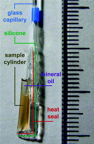
Fig. 3.
Sample preparation of egg extracts in transparent plastic cylinders. The photo shows a polytetrafluorethylen (PTFE) cylinder loaded with Xenopus laevis egg extract. The cylinder is formed using a 25-μm-thin transparent plastic foil. The bottom
 Histochemical Detection of Lipid Droplets in Cultured Cells
Environmental Scanning Electron Microscopy Gold Immunolabeling in Cell Biology
Histochemical Detection of Lipid Droplets in Cultured Cells
Environmental Scanning Electron Microscopy Gold Immunolabeling in Cell Biology
 Colocalization Analysis in Fluorescence Microscopy
 Morphological Analysis of Autophagy
 A Novel Combined Imaging/Morphometrical Method for the Analysis of Human Sural Nerve Biopsies for Clinical Diagnosis
 Environmental Scanning Electron Microscopy in Cell Biology


Related posts:
Histochemical Detection of Lipid Droplets in Cultured Cells
Environmental Scanning Electron Microscopy Gold Immunolabeling in Cell Biology
Colocalization Analysis in Fluorescence Microscopy
Morphological Analysis of Autophagy
Environmental Scanning Electron Microscopy in Cell Biology
Stay updated, free articles. Join our Telegram channel
Full access? Get Clinical Tree
