Fig. 9.1
The elements of a phased array immersion system, where a pair of sending and receiving elements are shown
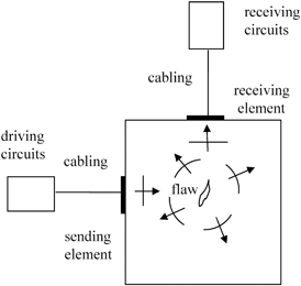
Fig. 9.2
The elements of a phased array contact testing system, where a pair of sending elements is shown
First consider the driving circuits in Figs. 9.1 and9.2. If we assume that these driving circuits can be represented by a linear active network, then Thévenin’s theorem says that in the frequency domain we can replace these driving circuits by an equivalent voltage source, and electrical impedance,
 as shown in Fig. 9.3 [Schmerr-Song]. These equivalent circuit elements will generate the same output voltage,
 and current,
 as the original driving circuit. Note that these equivalent parameters are affected by the choice of the phased array instrument settings that control the driving circuits.
 and electrical impedance,
 as shown in Fig. 9.3 [Schmerr-Song]. These equivalent circuit elements will generate the same output voltage,
 and current,
 as the original driving circuit. Note that these equivalent parameters are affected by the choice of the phased array instrument settings that control the driving circuits.
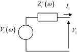
Fig. 9.3
An equivalent voltage source and electrical impedance model of the driving circuits
The driving circuits are connected to the sending element through the cabling present in the sound generation process. The voltage and current of the driving circuits at the input side of the cable produce corresponding voltage and current,
 at the output side. At the typical MHz frequencies present in an ultrasonic experiment, the electrical characteristics of the cabling can be important if the cabling lengths are on the order of a meter or more in length since in these cases the cable does not just pass the inputs unchanged to the outputs. It is reasonable to assume the cable is a simple passive linear, and reciprocal device that can be treated as a two-port system [Schmerr-Song] where the inputs and outputs can be related through a 2 × 2 transfer matrix ,
 as shown in Fig. 9.4. More explicitly we can write
 of the driving circuits at the input side of the cable produce corresponding voltage and current,
 at the output side. At the typical MHz frequencies present in an ultrasonic experiment, the electrical characteristics of the cabling can be important if the cabling lengths are on the order of a meter or more in length since in these cases the cable does not just pass the inputs unchanged to the outputs. It is reasonable to assume the cable is a simple passive linear, and reciprocal device that can be treated as a two-port system [Schmerr-Song] where the inputs and outputs can be related through a 2 × 2 transfer matrix ,
 as shown in Fig. 9.4. More explicitly we can write
Fig. 9.4
A two-port representation of a cable as a 2 × 2 transfer matrix
![$$ \left[ \begin{matrix} {{V}_{1}}\\ {{I}_{1}}\\\end{matrix} \right]=\left[ \begin{matrix} T_{11}^{\text{G}} & T_{12}^{\text{G}}\\ T_{21}^{\text{G}} & T_{22}^{\text{G}}\\\end{matrix} \right]\left[ \begin{matrix} {{V}_{2}}\\ {{I}_{2}}\\\end{matrix} \right], $$](/wp-content/uploads/2016/05/A314073_1_En_9_Chapter_Equ1.gif)
(9.1)
where the elements of the transfer matrix are frequency dependent. Since the cable is assumed to be reciprocal, the determinant of the transfer matrix must be unity [Schmerr-Song], i.e.
![$$ \det [ {{\mathbf{T}}^{\text{G}}} ]=T_{11}^{\text{G}}T_{22}^{\text{G}}-T_{12}^{\text{G}}T_{21}^{\text{G}}=1. $$](/wp-content/uploads/2016/05/A314073_1_En_9_Chapter_Equ2.gif)
(9.2)
The array driving element is normally made of a piezoelectric material and is attached to both backing and facing materials. Its function is to transform the electrical inputs of the cable attached to the element, into mechanical outputs at its face. The face is in contact with either a fluid (for the immersion case) or a solid (for the contact case). In the contact case a thin fluid layer between the face of the driving array and the underlying solid is normally present to ensure good coupling of sound into the solid . For both the immersion and contact cases the acoustic output properties of the element can be characterized by two “lumped” acoustic parameters—a compressive force,
 and velocity,
 both acting on the adjacent material. However, the detailed physics of the acoustic fields on the face of the element is modeled differently in the immersion and contact cases. In the immersion case , it is generally assumed that the face of the array at the element moves with the uniform velocity,
 normal to the face of the transducer and generates a spatially varying pressure distribution,
 over its face. The force,
 is then just the integral of this pressure distribution over the active area,
 of the driving element, i.e.
 into mechanical outputs at its face. The face is in contact with either a fluid (for the immersion case) or a solid (for the contact case). In the contact case a thin fluid layer between the face of the driving array and the underlying solid is normally present to ensure good coupling of sound into the solid . For both the immersion and contact cases the acoustic output properties of the element can be characterized by two “lumped” acoustic parameters—a compressive force,
 and velocity,
 both acting on the adjacent material. However, the detailed physics of the acoustic fields on the face of the element is modeled differently in the immersion and contact cases. In the immersion case , it is generally assumed that the face of the array at the element moves with the uniform velocity,
 normal to the face of the transducer and generates a spatially varying pressure distribution,
 over its face. The force,
 is then just the integral of this pressure distribution over the active area,
 of the driving element, i.e.
(9.3)
In contrast, in the contact case, since the face of the array is in contact with a stiff solid material through a thin fluid couplant, it is more reasonable to assume that piezoelectric element generates a constant pressure, at its face and the total force is just
 while the velocity field normal to the face has the distribution
 In this case the “lumped” parameter,
 can be taken to be the average velocity at the face:
 at its face and the total force is just
 while the velocity field normal to the face has the distribution
 In this case the “lumped” parameter,
 can be taken to be the average velocity at the face:
(9.4)
Thus, in either the immersion or contact testing setups, if we assume that the driving array elementA acts as a linear reciprocal system that transforms the electrical inputs to the mechanical outputs
 we can model this element also as a two-port system as shown in Fig. 9.5.
 to the mechanical outputs
 we can model this element also as a two-port system as shown in Fig. 9.5.
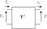
Fig. 9.5
A two-port model of an array element as a 2 × 2 transfer matrix
Explicitly, we then have
![$$ \left[ \begin{matrix} {{V}_{2}}\\ {{I}_{2}}\\\end{matrix} \right]=\left[ \begin{matrix} T_{11}^{A} & T_{12}^{A}\\ T_{21}^{A} & T_{22}^{A}\\\end{matrix} \right]\left[ \begin{matrix} {{F}_{\text{t}}}\\ {{v}_{\text{t}}}\\\end{matrix} \right]. $$](/wp-content/uploads/2016/05/A314073_1_En_9_Chapter_Equ5.gif)
(9.5)
Since the array element is assumed to satisfy reciprocity , we also have

(9.6)
At the acoustic output port of an array element the compressive force and velocity are not independent, reflecting the fact that if either the velocity on the face of the element or the pressure on the face of the element is specified then the other corresponding output parameter is also determined. This relationship is expressed as

(9.7)
where is theacoustic radiation impedance of the element. For ultrasonic immersion measurement systems that use large, single element transducers of circular cross section one can derive an explicit expression for this radiation impedance as [3])
 is theacoustic radiation impedance of the element. For ultrasonic immersion measurement systems that use large, single element transducers of circular cross section one can derive an explicit expression for this radiation impedance as [3])
![$$ {Z_{\text{r}}^{A;a}}/{{{\rho }_{1}}{{c}_{p1}}{{S}_{\text{A}}}}\;=1-{[ {{J}_{1}}( 2ka )-\text{i}{{S}_{1}}( 2ka ) ]}/{ka}\; $$](/wp-content/uploads/2016/05/A314073_1_En_9_Chapter_Equ8.gif)
(9.8)
where is a Bessel function of order one and
 is a Struve function. Here
 are the density and compressional wave speed of the fluid,a is the radius of the transducer,
 is the wave number, and
 . For most single element transducers
 can be a value of 100 or larger and Eq. (9.8) gives approximately
 which is just the acoustic impedance of a plane wave. While this same plane wave limit is also true for rectangular elements that are many wavelengths long in both dimensions, the rectangular elements often used in linear and 2-D arrays have at least one dimension which is not many wavelengths in size so that the acoustic radiation impedance will inherently be a complex function of frequency.
 is a Bessel function of order one and
 is a Struve function. Here
 are the density and compressional wave speed of the fluid,a is the radius of the transducer,
 is the wave number, and
 . For most single element transducers
 can be a value of 100 or larger and Eq. (9.8) gives approximately
 which is just the acoustic impedance of a plane wave. While this same plane wave limit is also true for rectangular elements that are many wavelengths long in both dimensions, the rectangular elements often used in linear and 2-D arrays have at least one dimension which is not many wavelengths in size so that the acoustic radiation impedance will inherently be a complex function of frequency.
Since the output force and velocity on the face of an element are related through the acoustic radiation impedance, we can model the driving circuits, cabling, and sending element as a series of two-port systems terminated at both ports, as shown in Fig. 9.6a, and we can replace this series of systems by a single input, single output linear time-shift invariant (LTI) system whose input is the Thevenin equivalent voltage, of the driving circuits. On the output side, we can take either the velocity,
 or the compressive force on the face of the array element,
 as the quantity to describe the acoustic fields. When modeling large, single element immersion transducers, it has been customary to use the force as the output [Schmerr-Song] where, as discussed above, the acoustic radiation impedance simply is a constant, i.e.
 For array elements in immersion tests we will continue to take the output as
 as shown in Fig. 9.6b but one should realize that this is really just an output proportional to the velocity having the dimensions of a force and not the actual compressive force on the face of the array element,
 which is given as
 We have made this choice because, as we will see, we can then develop complete models of ultrasonic phased arrays inspections without having to explicitly evaluate the radiation impedances of the elements. For array elements this evaluation must typically be done numerically, although it is not a difficult calculation for simple element shapes such as rectangles [4]. The transfer function for an immersion setup that describes the LTI system of Fig. 9.6b is denoted as
 For a contact setup, since the pressure is modeled as given at the transducer face, we will instead take the output of our LTI model to be the actual force,
 given by Eq. (9.3) and let
 be the transfer function in the contact case, as shown in Fig. 9.6c. Note that these transfer functions are explicit functions of all the system components shown in Fig. 9.6a but we will not need to write those explicit relationships here since
 and
and will not need to be independently known in a complete description of the ultrasonic system, as will be discussed in Sect. 9.4.
 of the driving circuits. On the output side, we can take either the velocity,
 or the compressive force on the face of the array element,
 as the quantity to describe the acoustic fields. When modeling large, single element immersion transducers, it has been customary to use the force as the output [Schmerr-Song] where, as discussed above, the acoustic radiation impedance simply is a constant, i.e.
 For array elements in immersion tests we will continue to take the output as
 as shown in Fig. 9.6b but one should realize that this is really just an output proportional to the velocity having the dimensions of a force and not the actual compressive force on the face of the array element,
 which is given as
 We have made this choice because, as we will see, we can then develop complete models of ultrasonic phased arrays inspections without having to explicitly evaluate the radiation impedances of the elements. For array elements this evaluation must typically be done numerically, although it is not a difficult calculation for simple element shapes such as rectangles [4]. The transfer function for an immersion setup that describes the LTI system of Fig. 9.6b is denoted as
 For a contact setup, since the pressure is modeled as given at the transducer face, we will instead take the output of our LTI model to be the actual force,
 given by Eq. (9.3) and let
 be the transfer function in the contact case, as shown in Fig. 9.6c. Note that these transfer functions are explicit functions of all the system components shown in Fig. 9.6a but we will not need to write those explicit relationships here since
 and
and will not need to be independently known in a complete description of the ultrasonic system, as will be discussed in Sect. 9.4.
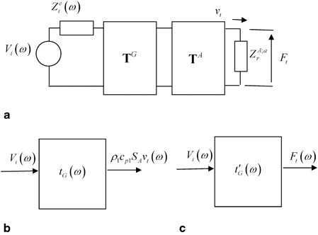
Fig. 9.6
a The sound generation process components, andb their replacement for an immersion inspection by a single input, single output linear time shift invariant system characterized by the transfer function, andc their replacement for a contact inspection by the transfer function
 andc their replacement for a contact inspection by the transfer function
9.2 Linear System Modeling and Sound Reception
The LTI models developed in the previous section can be used on sound generation for either immersion or contact phased array systems. In developing similar models for the sound reception processes it will be necessary to treat the immersion and contact cases separately. Consider first an immersion setup. Figure 9.7


Stay updated, free articles. Join our Telegram channel

Full access? Get Clinical Tree


