Lower Limb Alignment
Full-Length Anteroposterior Standing Radiograph
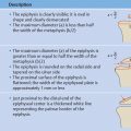
The full-length standing radiograph in the anteroposterior (AP) projection is the basic tool for the radiologic analysis of lower limb alignment.
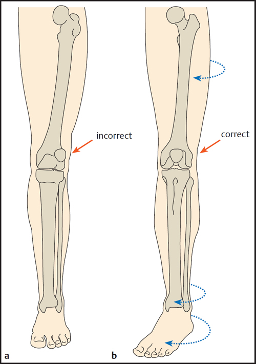
To correctly evaluate the alignment of the lower limbs in the frontal plane, the femoral condyles must be oriented parallel to the X-ray film. This is accomplished by directing the patellae forward while keeping both knee joints in a neutral position. The most important quality criterion for a full-length AP standing radiograph is to have the patellae centered between the femoral condyles ( Fig. 1.1 ).
Usually this position requires 8–10° of external rotation of the feet. With torsional deformities of the tibia that cause lateralization or medialization of the patella, the joint position is adjusted by rotating the lower leg internally or externally until the patella is pointing forward (regardless of the foot position, Fig. 1.2 ).
The lower limb has both anatomic and mechanical axes, which are distinguished as follows:
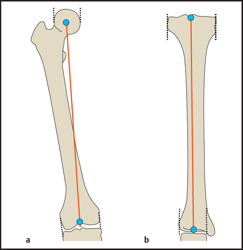
Anatomic axes ( Fig. 1.3 ): The anatomic axes of the femur and tibia coincide with the mid-diaphyseal line of each bone. They are defined by the midpoints of two widely spaced lines drawn perpendicular to the shaft.


Mechanical axes ( Fig. 1.4 ): The mechanical axes of the femur and tibia are defined by the center points of the adjacent joints. The mechanical axes of the femur and tibia form a physiologic varus angle of 1.2°.
Mechanical and Anatomic Axes of the Lower Limb
Mechanical Axis of the Lower Limb (Mikulicz Line)
The mechanical axis of the lower limb ( Fig. 1.5 ) is determined on the full-length AP standing radiograph. The axis passes through the center point of the hip joint (center of the femoral head) and through the center point of the ankle joint (midpoint of the tibial plafond). The mechanical axis should pass just medial to the center point of the knee joint. The lateral or medial mechanical axis deviation (MAD) from the center of the joint is measured in millimeters (mm).
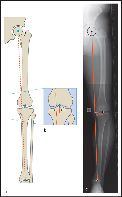
Mechanical axis of the lower limb
Normal values (medial deviation of the mechanical axis): 4 mm ± 4 mm (after Bhave et al) or 10 mm ± 7 mm (after Paley et al)
Genu valgum: greater lateral deviation (> normal value – standard deviation)
Genu varum: greater medial deviation (> normal value + standard deviation)
Anatomic Axis of the Lower Limb
The anatomic axis of the lower limb ( Fig. 1.6 ) is evaluated on the full-length AP radiograph by measuring the anatomic tibiofemoral angle, i.e., the upper acute angle formed by the anatomic axes of the femur and tibia.
Anatomic axis of the lower limb
• Normal values (anatomic tibiofemoral angle): | 6.85° ± 1.4° |
• Genu valgum: | > 8.3° |
• Genu varum: | < 0° |
Physiologically, the anatomic axes of the femur and tibia form a slight varus angle. A perfectly straight lower limb axis is therefore considered unphysiological. If the tibiofemoral angle is negative, genu varum is present.
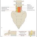
Basic Measuring Techniques for Planning Osteotomies
The deformity underlying an axial malalignment is analyzed by calculating the joint orientation angles. The basic reference lines for measuring these angles are the joint orientation lines shown in Fig. 1.7 . The joint orientation angle is measured between the joint orientation line and either the mechanical or anatomic axis. Paley introduced nomenclature that is useful for identifying a particular measurement based on the abbreviation of the joint orientation angle. The prefix “m” or “a” states whether an angle is measured relative to a mechanical or anatomic axis. The second letter indicates whether the angle is measured medial (M) or lateral (L) to the axis line. The next letters indicate whether the proximal (P) or distal (D) joint orientation angle has been measured for the femur (F) or the tibia (T). Because the anatomic and mechanical axes of the tibia are generally parallel, the “m” or “a” prefix may be omitted in the lower leg.


Logically, the medial and lateral angles relative to an axis add up to 180°. The usual practice is to state the angle that normally measures less than 90°. By general consensus, the proximal femoral angles are measured relative to the anatomic axis on the medial side and relative to the mechanical axis on the lateral side.
Figs. 1.8 and 1.9 and Table 1.1 show the angles relative to the joint orientation lines that are used in the planning of corrective osteotomies.
Paley D. Principles of deformity correction. Berlin: Springer; 2001Related posts:

Stay updated, free articles. Join our Telegram channel

Full access? Get Clinical Tree


