Chapter 1 Mammography Acquisition
Screen-Film and Digital Mammography, the Mammography Quality Standards Act, and Computer-Aided Detection
Randomized, controlled trials (RCTs) of women invited to mammography screening conducted between 1963 and 1990 showed that early detection and treatment of breast cancer led to a 25% to 30% decrease in breast cancer mortality. More recent studies of service screening in Sweden and Canada have shown that screening mammography can reduce breast cancer mortality by 40% to 50% compared to unscreened women (Tabar et al., Duffy et al., Coleman et al.). As a result, the American Cancer Society recommends that asymptomatic women age 40 years and older have an annual mammogram and receive a clinical breast examination as part of a periodic health examination, preferably annually (Saslow et al.) (Box 1-1).
In all of these studies, image quality was demonstrated to be a critical component of early detection of breast cancer. To standardize and improve the quality of mammography, in 1987 the American College of Radiology (ACR) started a voluntary ACR Mammography Accreditation Program (MAP). In 1992, the U.S. Congress passed the Mammography Quality Standards Act (MQSA; P.L. 102-539), which went into effect in 1994 and remains in effect today through reauthorizations in 1998, 2004, and 2007. MQSA mandates requirements for facilities performing mammography, including equipment and quality assurance requirements, as well as personnel qualifications for physicians, radiologic technologists, and medical physicists involved in the performance of mammography in the United States, whether screening or diagnostic, screen-film or digital (Box 1-2).
Box 1-2 Mammography Quality Standards Act of 1992
Congressional act to regulate mammography
Regulations enforced by the FDA require yearly inspections of all U.S. mammography facilities
All mammography centers must comply; noncompliance results in corrective action or closure
Falsifying information submitted to the FDA can result in fines and jail terms
Regulations regarding equipment, personnel credentialing and continuing education, quality control, quality assurance, and day-to-day operations
Technical Aspects of Mammography Image Acquisition
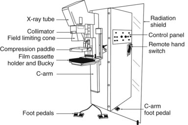
Mammograms are obtained on specially designed, dedicated x-ray machines using either x-ray film and paired fluorescent screens or digital detectors to capture the image. All mammography units are comprised of a rotating anode x-ray tube with matched filtration for soft-tissue imaging, a breast compression plate, a moving grid, an x-ray image receptor, and an automatic exposure control (AEC) device that can be placed under or detect the densest portion of the breast, all mounted on a rotating C-arm (Fig. 1-1). A technologist compresses the patient’s breast between the image receptor and compression plate for a few seconds during each exposure. Breast compression is important because it spreads normal fibroglandular tissues so that cancers, which have similar attenuation properties to fibroglandular tissues, can be better seen. Breast compression also decreases breast thickness, thereby decreasing exposure time, radiation dose to the breast, and the potential for image blurring as a result of patient motion and unsharpness.
The generator for a mammography system provides power to the x-ray tube. The peak kilovoltage (kVp) of mammography systems is lower than that of conventional x-ray systems, because it is desirable to use softer x-ray beams to increase both soft-tissue contrast and the absorption of x-rays in the cassette phosphor (absorption efficiency), especially for screen-film mammography (SFM). Typical kVp values for mammography are 24 to 32 kVp for molybdenum targets, 26 to 35 kVp for rhodium or tungsten targets. A key feature of mammography generators is the electron beam current (milliampere [mA]) rating of the system. The higher the mA rating, the shorter the exposure time for total tube output (milliampere second [mAs]). A compressed breast of average thickness (5 cm) requires about 150 mAs at 26 kVp to achieve proper film densities in SFM. If the tube rating is 100 mA (typical of the larger focal spots used for nonmagnification mammography), the exposure time would be 1.5 seconds. A higher-output system with 150-mA output would cut the exposure time to 1 second for the same compressed breast thickness and kVp setting. Because of the wide range of breast thicknesses, exposures require mAs values ranging from 10 to several hundred mAs. Specifications for generators are listed in Box 1-3.
Box 1-3 Mammography Generators
Half-value layer between kVp/100 + 0.03 and kVp/100 + 0.12 (in mm of aluminum) for Mo/Mo anode/filter material
Average breast exposure is 26–28 kVp (lower kVp for thinner or fattier breasts, higher kVp for thicker or denser breasts)
Screen-film systems deliver an average absorbed dose to the glandular tissue of the breast of 2 mGy (0.2 rad) per exposure
The most commonly used anode/filter combination is Mo/Mo: a molybdenum (Mo) anode (or target) and a Mo filter (25–30 microns thick), especially for thinner compressed breasts (<5 cm thick). Most current manufacturers also offer a rhodium (Rh) filter, to be used with the Mo target (Rh/Mo), to produce a slightly more penetrating (harder) x-ray beam for use with thicker breasts. Some manufacturers offer other target materials, such as Rh/Rh: a rhodium target paired with a rhodium filter, or tungsten (W), which is paired with a rhodium filter (W/Rh) or aluminum (Al) filter (W/Al). These anode/filter combinations are designed for thicker (>5 cm) and denser breasts. Typically, higher kVp settings are also used with these alternative target/filter combinations to result in a harder x-ray beam for thicker breasts, because fewer x-rays are attenuated with a harder x-ray beam (Box 1-4). One of the best parameters to measure the hardness or penetrating capability of an x-ray beam is the half-value layer (HVL), which represents the thickness of aluminum that reduces the exposure by one half. The harder the x-ray beam, the higher the HVL. The typical HVL for mammography is 0.3 to 0.5 mm of Al. The Food and Drug Administration (FDA) requires that the HVL for mammography cannot be less than kVp/100 ± 0.03 (in mm of Al), so that the x-ray beam is not too soft. For example, at 28 kVp, the HVL cannot be less than 0.31 mm of Al. There is also an upper limit on the half-value layer that depends on the target-filter combination. For the upper limit of Mo/Mo, the HVL must be less than kVp/100 + 0.12 (in mm of Al); so for 28 kVp, the HVL must be less than 0.4 mm of Al.
Box 1-4 Anode-Filter Combinations for Mammography
Ag, silver; Al, aluminum; Mo, molybdenum; Rh, rhodium; W, tungsten.
Geometric magnification is achieved by moving the breast farther from the image receptor (closer to the x-ray tube) and switching to a small focal spot (Fig. 1-2). Placing the breast halfway between the focal spot and the image receptor (as in Fig. 1-2B) would magnify the breast by a factor of 2.0 from its actual size to the image size because of the divergence of the x-ray beam. The MQSA requires that mammography units with magnification capabilities must provide at least one fixed magnification factor of between 1.4 and 2.0 (Table 1-1). Geometric magnification makes small, high-contrast structures such as microcalcifications more visible by making them larger relative to the noise pattern in the image (increasing their signal-to-noise ratio [SNR]). Optically or electronically magnifying a contact image, as would be done with a magnifier on SFM or using a zoom factor greater than 1 on a digital mammogram, does not increase the SNR of the object relative to the background, because both are increased in size equally. To avoid excess blurring of the image with geometric magnification, it is important to use a sufficiently small focal spot (usually 0.1 mm nominal size) and not too large a magnification factor (2.0 or less). When the small focal spot is selected for geometric magnification, the x-ray tube output is decreased by a factor of 3 to 4 (to 25–40 mA) compared to that from a large focal spot (80–150 mA). This can extend imaging times for magnification mammography, even though the grid is removed in magnification mammography. The air gap between the breast and image receptor provides adequate scatter rejection in magnification mammography without the use of an antiscatter grid.
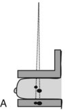
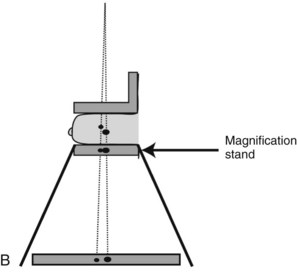
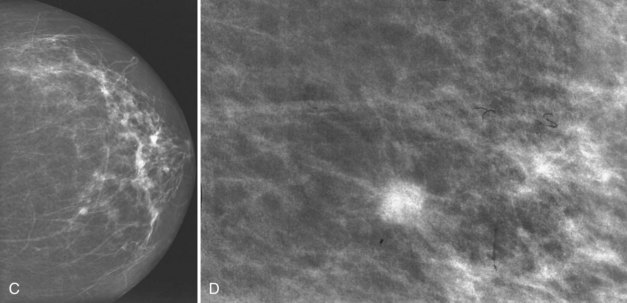
Table 1-1 Mammography Focal Spot Sizes and Source-to-Image Distances
| Mammography Type | Nominal Focal Spot Size (mm) | Source-to-Image Distance (cm) |
|---|---|---|
| Contact film-screen | 0.3 | ≥55 |
| Magnification | 0.1 | ≥55 |
The Mammography Quality Standards Act requires magnification factors between 1.4 and 2.0 for systems designed to perform magnification mammography.
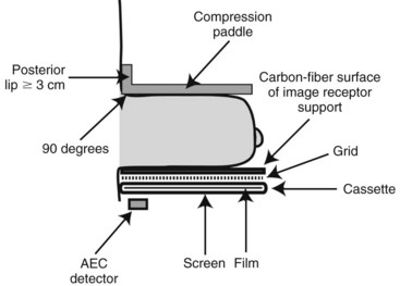
The compression plate and image receptor assembly hold the breast motionless during the exposure, decreasing the breast thickness and providing tight compression, better separating fibroglandular elements in the breast (Fig. 1-3). The compression plate has a posterior lip that is more than 3 cm high and usually is oriented at 90 degrees to the plane of the compression plate at the chest wall. This lip keeps chest wall structures from superimposing and obscuring posterior breast tissue in the image. The compression plate must be able to compress the breast for up to 1 minute with a compression force of 25 to 45 pounds. The compression plate can be advanced by a foot-controlled motorized device and adjusted more finely with hand controls.
Screen-Film Mammography Image Acquisition
In SFM, the image receptor assembly holds a screen-film cassette in a carbon-fiber support with a moving antiscatter grid in front of the cassette and an AEC detector behind it. Screen-film image receptors are required to be 18 × 24 cm and 24 × 30 cm in size to accommodate various sized breasts (Box 1-5). Each size image receptor must have a moving antiscatter grid composed of lead strips with a grid ratio (defined as the ratio of the lead strip height to the distance between strips) between 3.5 : 1 and 5 : 1. The reciprocating grid moves back and forth in the direction perpendicular to the grid lines during the radiographic exposure to eliminate grid lines in the image by blurring them out. One manufacturer uses a hexagonal-shaped grid pattern to improve scatter rejection; this grid is also blurred by reciprocation during exposure. Use of a grid improves image contrast by decreasing the fraction of scattered radiation reaching the image receptor. Grids increase the required exposure to the breast by approximately a factor of 2 (the Bucky factor), due to attenuation of primary as well as scattered radiation. Grids are not used with magnification mammography. Instead, in magnification mammography, scatter is reduced by collimation and by rejection of scattered x-rays due to a significant air gap between the breast and the image receptor.
Box 1-5 Compression Plate and Imaging Receptor
Both 18 × 24-cm and 24 × 30-cm sizes are required
A moving grid is required for each image receptor size
The compression plate has a posterior lip >3 cm and is oriented 90 degrees to the plane of the plate
Compression force of 25–45 pounds
Paddle advanced by a foot motor with hand compression adjustments
Film processing is affected by many variables, the most important of which are developer chemistry (weak or oxidized chemistry makes films lighter and lower contrast), developer temperature (too hot may make films darker, too cool lighter), developer replenishment (too little results in lighter, lower-contrast films), inadequate agitation of developer, and uneven application of developer to films (causes mottling) (Table 1-2).
Table 1-2 Variables Affecting Image Quality of Screen-Film Mammograms
| Film too dark | |
| Film too light | |
| Lost contrast | |
| Film turns brown | Inadequate rinsing of fixer |
| Motion artifact |
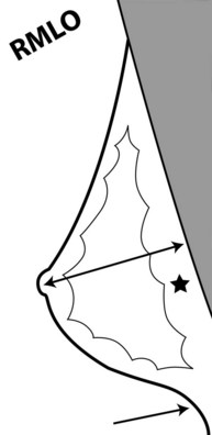
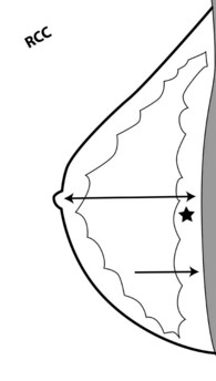
To pass ACR accreditation clinical image review, the MLO mammogram must show most of the breast tissue in one projection, with portions of the upper inner and lower inner quadrants partially excluded (Fig. 1-4). Clinical evaluation of the MLO view should show fat posterior to the fibroglandular tissue and a large portion of the pectoralis muscle, which should be concave and extend inferior to the posterior nipple line (PNL). The PNL describes an imaginary line drawn from the nipple to the pectoralis muscle or film edge and perpendicular to the pectoralis muscle. The PNL should intersect the pectoralis muscle in the MLO view in more than 80% of women. Although the technologist tries to avoid producing skin folds on the film when possible, they are seen occasionally but do not usually cause problems for the radiologist reading the film. The MLO view should show adequate compression, exposure, contrast, and an open inframammary fold, in which both the lower portion of the breast and a portion of the upper abdominal wall should be seen.
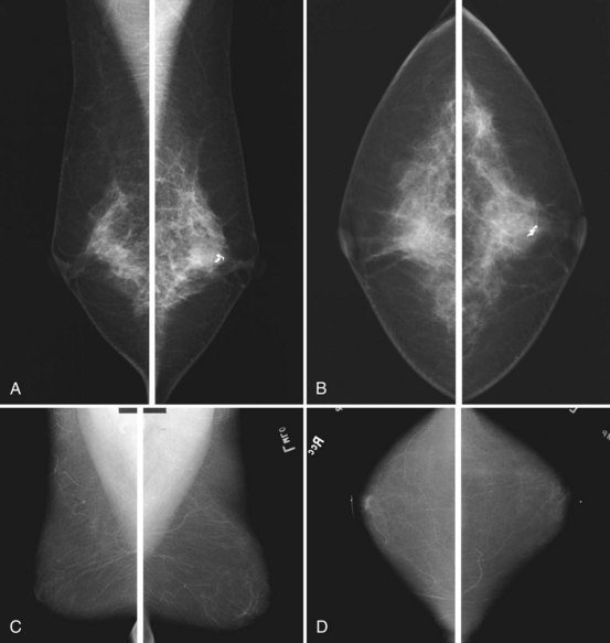
To pass ACR accreditation clinical image review, the CC view should include the medial posterior portions of the breast without sacrificing the outer portions (Figs. 1-5 and 1-6). With proper positioning technique, the technologist should be able to include the medial portion of the breast without rotating the patient medially by lifting the lower medial breast tissue onto the image receptor. The pectoralis muscle should be seen when possible on the CC view. On the CC view, the PNL extends from the nipple to the pectoralis muscle or the edge of the film, whichever comes first, perpendicular to the pectoralis muscle or film edge. For a given breast, the length of the PNL on the CC view should be within 1 cm of its length on the MLO view.
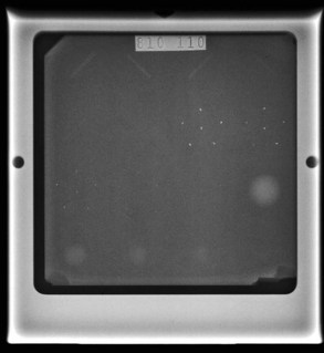
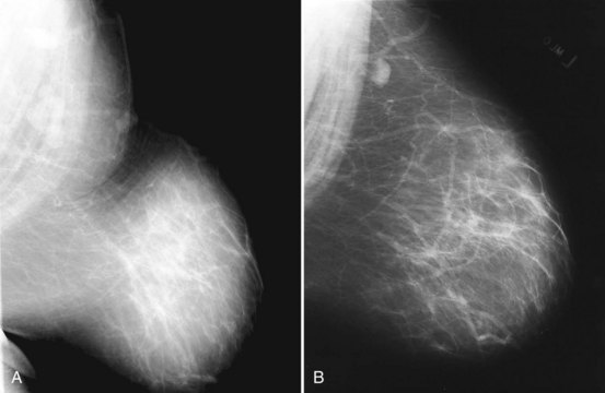
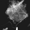
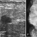
Clinical images are evaluated on positioning, compression, contrast, proper exposure, random noise (radiographic mottle or quantum mottle produced by varying numbers of x-rays contributing to the image in different locations, even with a uniform object), sharpness, and artifacts (or structured noise). Imaging on a phantom is helpful in evaluating most of these factors, except for positioning and compression (Fig. 1-7). Adequate exposure (to achieve adequate film OD) and adequate contrast (OD difference) are important to ensure detection of subtle abnormalities (Fig. 1-8). Artifacts seen on clinical images include processing artifacts (roller marks, wet pressure marks, guide shoe marks), white specklike artifacts from dust or lint between the fluorescent screen and film emulsion, grid lines from incomplete grid motion, motion artifacts from patient movement (made more likely by longer exposure times), skin folds from positioning, tree static caused by static electricity from low humidity in the dark room, or film handling artifacts (fingerprints, crimp marks, or pressure marks) (Figs. 1-9 to 1-12).