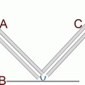
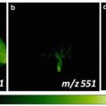
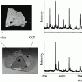
Fig. 1
Schematic draw of an electrochemical etching cell for SALDI substrate preparation. Adapted with permission from ref. 12
3.
Electrochemically etch the Si chip in the pSi etching solution for 1 min at a current density of 5 mA/cm2. After etching, carefully transfer the HF waste to a pre-labeled waste bottle in the hood dedicated to HF. Wash the setup with 95 % ethanol thoroughly before disassembly. Wash the produced pSi substrate again with copious amounts of 95 % ethanol and dry the substrate under N2.
4.
To double-etch the pSi substrate, first dip the substrate in the pSi oxidation solution for 1 min, followed by washing in 95 % ethanol, drying in a N2 stream, and dipping in the pSi wash solution for 1 min. Wash the substrate again in 95 % ethanol and store in ethanol until needed (see Note 3 ).
5.
Prior to usage, refresh the substrates in the pSi wash solution for 1 min again, wash in 95 % ethanol, and dry with N2.
3.2 Synthesis of Solid Ionic Matrix
1.
Dissolve 38.5 mg of CHCA in 20 mL of methanol in a round-bottom flask. Add 16.6 mL of Py or 18.7 mL of ANI into the CHCA solution.
2.
Stir the reaction mixture for 2 h at room temperature.
3.
Remove the solvent by rotovap and dry the yielded solid ionic matrix under vacuum.
4.
Store CHCA/ANI under vacuum at room temperature before use.
3.3 Tissue Section Preparation
1.
Precut fresh garlic glove tissues into thin slices using carbon steel surgical blades with at least one dimension no less than 2 mm. Snap freeze all thin tissue slices in liquid N2 immediately and store at −80 °C prior to usage (see Note 4 ).
2.
Use a cryo-cut microtome equipped with stainless-steel microtome knives for tissue sectioning. Procedural modification may be needed when different equipment is being used. Mount the frozen tissue slice onto the microtome chunk, using the OCT compound as a “glue” to hold to tissue in place. Slowly bring the temperature up to −20 °C. Section the frozen tissue samples into 10-μm-thick slices. Transfer the 10-μm-thick tissue slices onto a dry pSi substrate and slowly bring it up to room temperature.
3.
Meanwhile, transfer the adjacent section of the same tissue chunk onto a microscope glass slide for conventional histological staining. Deposit the methylene blue staining solution (0.15 %, 200 μL) onto the tissue section. After 10 s of staining, wash the excess staining solution away with 95 % ethanol.
4.
Use an optical microscope equipped with a digital camera to collect the optical images of stained tissue sections to provide visual validation of MSI data.
3.4 Matrix Deposition
1.
2.
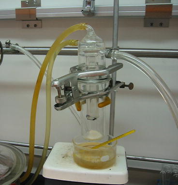
Add 0.3 g of CHCA, DHB, CHCA/Py, or CHCA/ANI to the bottom of the sublimation chamber.
3.
Attach the tissue-coated porous Si to the flat bottom of the apparatus condenser, facing downwards to the matrix.
4.
Cool the condenser, along with the porous silicon substrate, with running water for vapor condensation (see Note 5 ).
5.
Preheat the silicon oil bath to 110 °C for DHB, to 113 °C for CHCA/Py, to 120 °C for CHCA, or to 170 °C for CHCA/ANI. Maintain the chamber pressure at ~50 Torr for 2 min before immersing the sublimation glassware into oil bath.
6.
For CHCA or CHCA/Py, heat the sublimation setup for 5 min. Use a 10-min heating time for CHCA/ANI sublimation and a 1–5-min heating time for DHB sublimation (see Note 6 ).
7.
Remove the sublimation setup from the oil bath and release the vacuum gently when the sublimation chamber cools down to the room temperature. Take the pSi substrate coated with matrix out of the sublimation apparatus and immediately load it into the MS sample chamber for MS analysis. Turn off the vacuum pump, the cooling water, and the hot plate. Excess matrix left in the sublimation chamber can be saved in a separate bottle for future usage but not to be put back to the original bottle to avoid contamination.
3.5 Mass Spectrometry Imaging
Modification in instrumental conditions may be needed to achieve optimal imaging results when different instruments are used.
1.


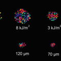
The mass spectrometer used in this protocol is equipped with a 20-Hz N2 laser. Adjust the laser irradiation energy by a neutral density filter and the beam size to 35 μm with an adjustable pinhole placed close to the laser entrance window. The actual laser beam size can be measured by increasing laser fluence till a burn mark is left behind on a SALDI substrate to allow off-line measurements of the laser beam footprint (see Note 7 ).
Stay updated, free articles. Join our Telegram channel

Full access? Get Clinical Tree


