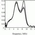
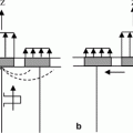
Fig. 11.1
A “fields” parameter model of a coaxial cable showing the electrical and magnetic fields at the cable ends
(11.1)
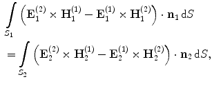
where  are the electrical and magnetic fields at one end of the cable and
  are the electrical and magnetic fields at the other end (Fig. 11.1). The unit vectors
  are the outward unit normals at the ends, as shown in Fig. 11.1, and
  are the cross-sectional areas of the cables at their ends over which the field values in Eq. (11.1) are calculated. The superscripts (1) and (2) on these fields denote two different driving/termination conditions under which these fields are measured.
 are the electrical and magnetic fields at one end of the cable and
  are the electrical and magnetic fields at the other end (Fig. 11.1). The unit vectors
  are the outward unit normals at the ends, as shown in Fig. 11.1, and
  are the cross-sectional areas of the cables at their ends over which the field values in Eq. (11.1) are calculated. The superscripts (1) and (2) on these fields denote two different driving/termination conditions under which these fields are measured.
Instead of using the field values explicitly in a reciprocity relationship, one can also use “lumped parameters.” For the cable , for example, we can express the voltages and currents produced by these underlying fields in a similar reciprocity relationship given as (see Fig. 11.2)

Fig. 11.2
A “lumped” parameter model of a coaxial cable showing the voltage and current at the cable ends

(11.2)
where  and
and  are the voltages and currents at the cable ends, and (1) and (2) again denote two different “states” under which these lumped parameters are measured.
 and
and  are the voltages and currents at the cable ends, and (1) and (2) again denote two different “states” under which these lumped parameters are measured.
Reciprocity relations can also be developed that mix lumped parameters and field parameters. For example, in describing the inputs and outputs of a sending array element in an immersion test one can use lumped parameters of voltage and current  on the electrical driving side of the element and acoustic pressure and vector velocity fields
  over the output face of the element to express the reciprocal theorem for an array element in the form
 on the electrical driving side of the element and acoustic pressure and vector velocity fields
  over the output face of the element to express the reciprocal theorem for an array element in the form
(11.3)
where states (1) and (2) again are two different driving and termination conditions for the array element and  is the unit outward normal to the element surface (Fig. 11.3a). Alternatively, reciprocity for the element could be expressed completely in terms of lumped parameters. If we assume the element in this immersion test acts a “piston”, for example, then
  and Eq. (11.3) reduces to
 is the unit outward normal to the element surface (Fig. 11.3a). Alternatively, reciprocity for the element could be expressed completely in terms of lumped parameters. If we assume the element in this immersion test acts a “piston”, for example, then
  and Eq. (11.3) reduces to
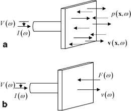
Fig. 11.3
a A “mixed” model of an array element with lumped parameters of voltage and current defining the inputs and pressure and velocity fields at the output face of the element, and b a model of an array element with voltage and currents at the input and compressive force and normal velocity at the output

(11.4)
where  is the force produced by the integral of the pressure over the face of the element and
  is the (uniform) normal velocity (Fig. 11.3b).
 is the force produced by the integral of the pressure over the face of the element and
  is the (uniform) normal velocity (Fig. 11.3b).
In considering the acoustic and elastic wave fields between the sending and receiving array elements in a flaw measurement (see Fig. 11.4), it is possible to also derive a reciprocity relation that connects the fields on the flaw surface to the force and velocity on the face of the receiving element. The details of how this reciprocity relationship is obtained have been presented elsewhere [Schmerr–Song] so we will only state the reciprocity relationship here. It is
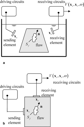
Fig. 11.4
a An immersion flaw inspection with a pair of sending and receiving array elements, and b a corresponding contact flaws inspection with sending and receiving elements

(11.5)
Here states (1) and (2) are two specific states. State (1) is the actual flaw measurement setup where the flaw is present while state (2) is where the receiving element acts as a transmitter instead of a receiver, and the flaw is absent. The parameters  are the force and normal velocity on the receiving element produced by the waves scattered from the flaw in state (1) while
  are the force and normal velocity on the face of the receiving element when it acts as a transmitter in state (2). The fields
  are the stresses and velocity components on the surface,
  of the flaw, whose outward unit normal components are
  (see Fig. 11.4a, b). This reciprocity relationship can also be written in the alternate form
 are the force and normal velocity on the receiving element produced by the waves scattered from the flaw in state (1) while
  are the force and normal velocity on the face of the receiving element when it acts as a transmitter in state (2). The fields
  are the stresses and velocity components on the surface,
  of the flaw, whose outward unit normal components are
  (see Fig. 11.4a, b). This reciprocity relationship can also be written in the alternate form
(11.6)
where  are the components of the traction vector,
  acting on the surface of the flaw.
 are the components of the traction vector,
  acting on the surface of the flaw.
Although Eqs. (11.5) and (11.6) were derived in [Schmerr–Song] explicitly for the immersion case, both of these equations are applicable to either the immersion or contact testing setups shown in Fig. 11.4. This can be seen by writing these reciprocity relations entirely in terms of the underlying fields on the face of the receiving element. Equation (11.5), for example, then becomes

(11.7)
which is true for both the contact and immersion cases since in the immersion case the stress fields at the acoustic port of the element are purely pressure fields and in the contact case there is a fluid couplant between the element and the adjacent solid so again there is only a pressure on the surface of the element. Here  are the pressure and velocity fields on the receiving element due to waves scattered from the flaw. But in the contact case, if we assume this pressure is uniform in both states, i.e.
  and
and  , then the forces on the receiving element face are just
  and
and  Then, if we define the average normal velocities on the face of the receiving element in either state as
 are the pressure and velocity fields on the receiving element due to waves scattered from the flaw. But in the contact case, if we assume this pressure is uniform in both states, i.e.
  and
and  , then the forces on the receiving element face are just
  and
and  Then, if we define the average normal velocities on the face of the receiving element in either state as
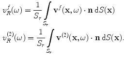
(11.8)
Equation (11.7) again reduces to Eq. (11.5).
11.2 An Ultrasonic Measurement Model for Immersion Setups
Consider an immersion flaw measurement setup . In state (2) where the receiving element B is acting as a transmitter, the force  and normal velocity
  are related through the acoustic radiation impedance ,
  of the receiving element, i.e.
 and normal velocity
  are related through the acoustic radiation impedance ,
  of the receiving element, i.e.
(11.9)

(11.10)
But the quantity in parentheses on the left side of Eq. (11.10) is just the blocked force ,  generated on the receiving element by the flaw fields (see Eq. (9.10), with
  since
since  in that equation is directed inward to the element face) so that
 generated on the receiving element by the flaw fields (see Eq. (9.10), with
  since
since  in that equation is directed inward to the element face) so that
(11.11)
Dividing this result by  where
where  are the density and wave speed at the sending element A, which has an area,
  , and a uniform velocity,
  , over that area in state (1), we find an expression for the acoustic/elastic transfer function (see Eq. (9.24)), namely
 where
where  are the density and wave speed at the sending element A, which has an area,
  , and a uniform velocity,
  , over that area in state (1), we find an expression for the acoustic/elastic transfer function (see Eq. (9.24)), namely
(11.12)
Since the received voltage,  , for a sending element located at
  and a receiving element located at
  (see Fig. 11.4) is just proportional to this transfer function through the system function,
  , for the pair of sending and receiving elements present, we have
 , for a sending element located at
  and a receiving element located at
  (see Fig. 11.4) is just proportional to this transfer function through the system function,
  , for the pair of sending and receiving elements present, we have
(11.13)
Equation (11.13) is an ultrasonic measurement model for an arbitrary pair of elements in an immersion flaw inspection (Fig. 11.4a). It predicts the frequency spectrum of the measured voltage in terms of the system function, which can be measured in a calibration setup as shown in Chap. 10, and the fields on the surface of the flaw in states (1) and (2) . These fields are normalized by driving velocities on the faces of the sending and receiving elements in states (1) and (2) respectively, so that one only needs to calculate the fields in Eq. (11.13) for cases where the driving velocity is unity on the faces of these elements. If appropriate ultrasonic beam models and flaw scattering models are available, these normalized fields can be directly calculated and one does not need to know the actual velocities on these element faces for the models involved .
11.3 An Ultrasonic Measurement Model for Contact Setups
One can again start with Eq. (11.10) since the force and average velocity lumped parameters are again related through the acoustic radiation impedance (Eq. 11.9 for state (2)) . However, we can rewrite Eq. (11.10) as

(11.14)
In the contact case, we can recognize the term in parentheses on the left side of Eq. (11.14) as the free surface velocity (see Eq. (9.11) with  again since v is directed inward to the transducer face) so we have
 again since v is directed inward to the transducer face) so we have
(11.15)
In Chap. 10 we saw that a system function having the same dimensions as the measured voltage, could be obtained by using a non-dimensional transfer function in the contact case defined as  where
where  is the compressive force exerted on the face of the driving element in state (1) and
  are the density and compressional wave speed of the solid adjacent to the receiving element whose area is
  . From Eq. (11.15) then we have
 where
where  is the compressive force exerted on the face of the driving element in state (1) and
  are the density and compressional wave speed of the solid adjacent to the receiving element whose area is
  . From Eq. (11.15) then we have
(11.16)
and a complete measurement model for the received voltage for the contact case (Fig. 11.4b) is

(11.17)
In Eq. (11.17) we see the fields on the surface of the flaw are normalized by the forces on the faces of driving elements in states (1) and (2). Thus, as in the immersion case, we do not need to know the actual driving forces (or underlying pressures) in the contact case to model these wave fields .
Measurement models similar to those given by Eqs. (11.13) and (11.17) were originally obtained by Auld [1] using general electromechanical reciprocity conditions. Because such measurement models are based primarily on assumptions of linearity and reciprocity they are applicable to almost all NDE inspections. Since Auld’s seminal paper there have been numerous applications where these measurement models have been coupled with ultrasonic beam models and flaw scattering models to simulate the signals seen in NDE inspections. Many of these applications have been described in the Proceedings of the Review of Progress in Quantitative NDE meetings [5]. To date, measurement models have been mostly used to simulate inspections with large single element transducers but as we have seen here they are also applicable to any arbitrary pair of sending and receiving elements. By simply considering the ensemble of all pairs of sending/receiving element responses and by incorporating the appropriate time delay laws and/or apodization laws these measurement models are also applicable to virtually any ultrasonic inspection using one or more arrays .
11.4 A Reduced Measurement Model for Small Flaws
Although the measurement models of the Auld type discussed in the previous sections have the advantage of being very general, the flaw response is contained in those models only through the fields on the flaw surface, making it difficult to connect the measured voltage response with any specific flaw characteristic or flaw parameter . Since the purpose of most ultrasonic NDE flaw inspections is to make that connection and predict flaw properties from the measured signals, it would be useful to be able to have a measurement model that contains the flaw response in a more explicit fashion. Fortunately, this is possible with a relatively few additional assumptions. The details have been given elsewhere, [Schmerr], [Schmerr-Song], so here we will briefly outline the steps.
The basic assumptions we will make are (1) that the waves incident on the flaw in states (1) and (2) can be treated as quasi-plane waves, and (2) that the flaw is small enough so that the amplitude of these waves does not vary significantly over the flaw surface, so we can take the amplitude of these waves as evaluated at a fixed point,  , (see Fig. 11.5) which is usually taken to be the center of the flaw for simple flaw shapes. Consider first the case of immersion testing where the waves are generated in states (1) and (2) by elements having uniform velocities
  on their faces. The velocity components of the incident quasi-plane waves in states (1) and (2) on the flaw can be written as
 , (see Fig. 11.5) which is usually taken to be the center of the flaw for simple flaw shapes. Consider first the case of immersion testing where the waves are generated in states (1) and (2) by elements having uniform velocities
  on their faces. The velocity components of the incident quasi-plane waves in states (1) and (2) on the flaw can be written as
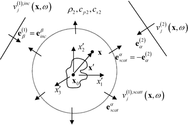
Fig. 11.5
The waves incident on a flaw from states (1) and (2) treated as quasi-plane waves
![$$\begin{matrix}v_{j}^{(1);inc}(\mathbf{x},\omega )=v_{T}^{(1)}(\omega ){{{\hat{V}}}^{(1)}}\left( {{\mathbf{x}}_{s}},{{\mathbf{x}}_{0}},\omega \right)d_{\beta j}^{(1)}\exp [i{{k}_{\beta 2}}\mathbf{e}_{\beta }^{(1)}\cdot \left( \mathbf{x}-{{\mathbf{x}}_{0}} \right)] \\v_{j}^{(2)}(\mathbf{x},\omega )=v_{R}^{(2)}(\omega ){{{\hat{V}}}^{(2)}}\left( {{\mathbf{x}}_{r}},{{\mathbf{x}}_{0}},\omega \right)d_{\alpha j}^{(2)}\exp [i{{k}_{\alpha 2}}\mathbf{e}_{\alpha }^{(2)}\cdot \left( \mathbf{x}-{{\mathbf{x}}_{0}} \right)], \\\end{matrix}$$](/wp-content/uploads/2016/05/A314073_1_En_11_Chapter_Equ18.gif)
(11.18)
where  are the unit vector polarizations of the incident waves in states (1) and (2), which are traveling in the direction of the unit vectors
  and
and  are the wave numbers of the incident waves, which can be of type
 for state (1) and type
 for state (2) corresponding to either P-waves or S-waves where
  are the density, compressional wave speed, and shear wave speed, respectively, for the medium surrounding the flaw. In Eq. (11.18) we will let
  be the coordinates of the position vector
  as measured with respect to the fixed point,
  , as shown in Fig. 11.5. Note that the total velocity at the flaw in state (1) is given by the sum of the incident and scattered waves, i.e.
  (see Fig. 11.5), so we need to identify the waves in Eq. (11.18) as only those incident waves. In state (2) no flaw is present so the total velocity fields are just the incident fields of Eq. (11.18). Also, in state (2), the stresses,
  , can be calculated since
 are the unit vector polarizations of the incident waves in states (1) and (2), which are traveling in the direction of the unit vectors
  and
and  are the wave numbers of the incident waves, which can be of type
 for state (1) and type
 for state (2) corresponding to either P-waves or S-waves where
  are the density, compressional wave speed, and shear wave speed, respectively, for the medium surrounding the flaw. In Eq. (11.18) we will let
  be the coordinates of the position vector
  as measured with respect to the fixed point,
  , as shown in Fig. 11.5. Note that the total velocity at the flaw in state (1) is given by the sum of the incident and scattered waves, i.e.
  (see Fig. 11.5), so we need to identify the waves in Eq. (11.18) as only those incident waves. In state (2) no flaw is present so the total velocity fields are just the incident fields of Eq. (11.18). Also, in state (2), the stresses,
  , can be calculated since
(11.19)
where  is the tensor of elastic constants [Schmerr]. Placing Eqs. (11.18) and (11.19) into the measurement model of Eq. (11.13) gives
 is the tensor of elastic constants [Schmerr]. Placing Eqs. (11.18) and (11.19) into the measurement model of Eq. (11.13) gives
(11.20)
If we now normalize the stresses and velocity components in state (1) by the displacement amplitude,  , of the incident wave in that state, we can define these normalized fields as
 , of the incident wave in that state, we can define these normalized fields as
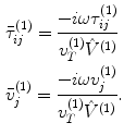
(11.21)
Then Eq. (11.20) can be rewritten as
![$$ \begin{matrix} V( {{\mathbf{x}}_{s}},{{\mathbf{x}}_{r}},\omega)={{s}_{I}}(\omega )\frac{{{{\hat{V}}}^{(1)}}( {{\mathbf{x}}_{s}},{{\mathbf{x}}_{0}},\omega){{{\hat{V}}}^{(2)}}( {{\mathbf{x}}_{r}},{{\mathbf{x}}_{0}},\omega)}{-i\omega {{\rho }_{1}}{{c}_{p1}}{{S}_{A}}}\\ \cdot \int\limits_{{{S}_{f}}}{\left( \bar{\tau }_{ji}^{(1)}(\mathbf{x},\omega )d_{\alpha i}^{(2)}(\mathbf{x},\omega )+{{C}_{ijkl}}\frac{e_{l}^{(2)}}{{{c}_{\alpha 2}}}d_{\alpha k}^{(2)}\bar{v}_{i}^{(1)}(\mathbf{x},\omega ) \right){{n}_{j}}(\mathbf{x})\exp [ i{{k}_{\alpha 2}}\mathbf{e}_{\alpha }^{(2)}\cdot \mathbf{{x}'} ]\text{d}S(\mathbf{{x}'}).}\\\end{matrix} $$](/wp-content/uploads/2016/05/A314073_1_En_11_Chapter_Equ22.gif)
(11.22)
Equation (11.22) contains the flaw response in an explicit form. This can be seen by considering the canonical problem of a flaw in an infinite medium acted upon by a incident plane wave of type 
 traveling in the
  direction and having a unit displacement amplitude, as shown in Fig. 11.6. In the far-field of the flaw a scattered wave of type
 traveling in the
  direction is a spherically spreading wave of polarization
  having the displacements

 traveling in the
  direction and having a unit displacement amplitude, as shown in Fig. 11.6. In the far-field of the flaw a scattered wave of type
 traveling in the
  direction is a spherically spreading wave of polarization
  having the displacements
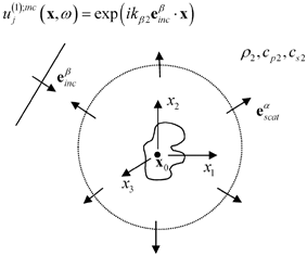
Fig. 11.6
The far field scattering of a wave of type  due to a plane wave of type
  having a unit displacement amplitude
 due to a plane wave of type
  having a unit displacement amplitude
(11.23)
Here  is the vector far-field scattering amplitude whose components are given by
 is the vector far-field scattering amplitude whose components are given by
![$$ \begin{aligned}& {{A}_{n}}( \mathbf{e}_{\text{inc}}^{\beta },\mathbf{e}_{\text{scat}}^{\alpha },\omega)=-\frac{d_{s;n}^{\alpha }}{4\text{ }\!\!\pi\!\!\text{ }{{\rho }_{2}}c_{\alpha 2}^{2}} \\& \int\limits_{{{S}_{f}}}{\left( \bar{\tau }_{ji}^{(1)}(\mathbf{x},\omega )d_{s;i}^{\alpha }(\mathbf{x},\omega )-{{C}_{ijkl}}\frac{e_{\text{scat}\,;l}^{\alpha }}{{{c}_{\alpha 2}}}d_{s;k}^{\alpha }\bar{v}_{i}^{(1)}(\mathbf{x},\omega ) \right){{n}_{j}}(\mathbf{x})\exp [{-}i{{k}_{\alpha 2}}\mathbf{e}_{\text{scat}}^{\alpha }\cdot \mathbf{{x}'} ]\text{d}S(\mathbf{{x}'}).} \\ \end{aligned} $$](/wp-content/uploads/2016/05/A314073_1_En_11_Chapter_Equ24.gif)
(11.24)
![$$ \begin{array}{*{35}{l}} \int\limits_{{{S}_{f}}}{\left( \bar{\tau }_{ji}^{(1)}(\mathbf{x},\omega )d_{\alpha i}^{(2)}(\mathbf{x},\omega )+{{C}_{ijkl}}\frac{e_{\alpha l}^{(2)}}{{{c}_{\alpha 2}}}d_{\alpha k}^{(2)}\bar{v}_{i}^{(1)}(\mathbf{x},\omega ) \right){{n}_{j}}(\mathbf{x})\exp [ i{{k}_{\alpha 2}}\mathbf{e}_{\alpha }^{(2)}\cdot \mathbf{{x}'} ]\text{d}S(\mathbf{{x}'})}\\[8pt] =4\text{ }\!\!\pi\!\!\text{ }{{\rho }_{2}}c_{\alpha 2}^{2}[ \mathbf{A}( \mathbf{e}_{inc}^{\beta },\mathbf{e}_{scat}^{\alpha },\omega)\cdot ({-}{{\mathbf{d}}^{(2)}} ) ]\\[8pt]\end{array} $$](/wp-content/uploads/2016/05/A314073_1_En_11_Chapter_Equ25.gif)
(11.25)
and Eq. (11.22) becomes
![$$ V( {{\mathbf{x}}_{s}},{{\mathbf{x}}_{r}},\omega)={{s}_{I}}(\omega ){{\hat{V}}^{(1)}}( {{\mathbf{x}}_{s}},{{\mathbf{x}}_{0}},\omega){{\hat{V}}^{(2)}}( {{\mathbf{x}}_{r}},{{\mathbf{x}}_{0}},\omega)A( \mathbf{e}_{inc}^{\beta },\mathbf{e}_{scat}^{\alpha },\omega)\left[ \frac{4\text{ }\!\!\pi\!\!\text{ }{{\rho }_{2}}{{c}_{\alpha 2}}}{-i{{k}_{\alpha 2}}{{\rho }_{1}}{{c}_{p1}}{{S}_{A}}} \right], $$](/wp-content/uploads/2016/05/A314073_1_En_11_Chapter_Equ26.gif)
(11.26)
where  is the scalar component of the vector scattering amplitude given as
 is the scalar component of the vector scattering amplitude given as
![$$ A( \mathbf{e}_{\text{inc}}^{\beta },\mathbf{e}_{\text{scat}}^{\alpha },\omega)=[ \mathbf{A}( \mathbf{e}_{\text{inc}}^{\beta },\mathbf{e}_{\text{scat}}^{\alpha },\omega)\cdot ({-}{{\mathbf{d}}^{(2)}} ) ]. $$](/wp-content/uploads/2016/05/A314073_1_En_11_Chapter_Equ27.gif)
(11.27)
The contact case follows similar steps. First, the incident waves are expressed as quasi-plane waves of the form

(11.28)
where  are the density and compressional wave speed, respectively, in the solid adjacent to the receiving element and
  are the corresponding parameters at the sending element. These densities and wave speeds are the same in contact tests where the sending and receiving elements are in contact with the same medium but for generality we have left them different. Similarly,
  are denoted as the possibly different density and wave speed (of the scattered wave) surrounding the flaw.
 are the density and compressional wave speed, respectively, in the solid adjacent to the receiving element and
  are the corresponding parameters at the sending element. These densities and wave speeds are the same in contact tests where the sending and receiving elements are in contact with the same medium but for generality we have left them different. Similarly,
  are denoted as the possibly different density and wave speed (of the scattered wave) surrounding the flaw.
Second, the stresses and velocities in state (1) are normalized so that the incident plane wave in that state is of unit displacement amplitude:
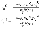
(11.29)
Then Eq. (11.17) reduces to
Stay updated, free articles. Join our Telegram channel

Full access? Get Clinical Tree


