Measurement of Ionizing Radiation
6.1. INTRODUCTION
In the early days of x-ray usage for diagnosis and therapy, attempts were made to measure ionizing radiation on the basis of chemical and biologic effects. For instance, radiation effects on photographic emulsions, changes in the color of some chemical compounds, and reddening of the human skin could be related to the amount of radiation absorbed. However, these effects were poorly understood at the time and could only provide a crude estimation of radiation dose. For example, in radiotherapy, a unit called skin erythema dose (SED) was defined as that amount of x- or γ-radiation that just produced reddening of the human skin. However, the unit has many drawbacks. Skin erythema depends on many conditions, such as the type of skin, the quality of radiation, the extent of skin exposed, dose fractionation (dose per fraction and interval between fractions), and differences between early and delayed skin reactions.
Although the SED was later discarded in favor of a more precisely measurable unit such as the roentgen, the skin erythema was used by physicians as an approximate index of response to the radiation treatments. This happened in the orthovoltage era when the skin was the limiting organ to the delivery of tumoricidal doses. The reliance on skin reaction for the assessment of radiation response had to be abandoned when megavoltage beams with the skin-sparing properties became the main tools of radiation therapy.
In 1928, the International Commission on Radiation Units and Measurements (ICRU) adopted the roentgen as the unit of measuring x- and γ-radiation exposure. The unit is denoted by R. It may be mentioned at this point that the quantity exposure measured in R can be converted into a quantity called absorbed dose (to be discussed in Chapter 8).
6.2. THE ROENTGEN
The roentgen is a unit of exposure. The quantity exposure is a measure of ionization produced in air by photons. The ICRU (1) defines exposure (X) as the quotient of dQ by dm where dQ is the absolute value of the total charge of the ions of one sign produced in air when all the electrons (negatrons and positrons) liberated by photons in air of mass dm are completely stopped in air:
The SI unit for exposure is coulomb per kilogram (C/kg), but the special unit is roentgen (R):1
1 R = 2.58 × 10⁻⁴ C/kg air
The definition of roentgen is illustrated in Figure 6.1. An x-ray beam in passing through air sets in motion electrons by photoelectric effect, Compton effect, or pair production. These high-speed electrons produce ionization along their tracks. Because of the electric field produced by the voltage applied across the ion-collection plates, the positive charges move toward the negative plate and the negative charges move toward the positive plate. This constitutes a current. The collected charge of either sign can be measured by an electrometer.
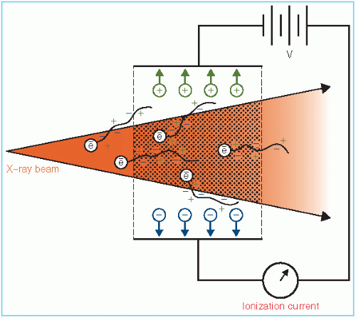 Figure 6.1. Diagram illustrating electronic equilibrium in a free-air chamber. |
According to the definition of roentgen, the electrons produced by photons in a specified volume (shaded in Fig. 6.1) must spend all their energies by ionization in air enclosed by the plates (region of ion collection) and the total ionic charge of either sign should be measured. However, some electrons produced in the specified volume deposit their energy outside the region of ion collection and thus are not measured. On the other hand, electrons produced outside the specified volume may enter the ion-collecting region and produce ionization there. If the ionization loss is compensated by the ionization gained, a condition of electronic equilibrium exists. Under this condition, the definition of roentgen is effectively satisfied. This is the principle of the free-air ionization chamber, described below.
1Roentgen was originally defined as 1 R = 1 electrostatic unit (esu)/cm3 air at standard temperature and pressure (STP) (0°C, 760 mmHg). The current definition of 1 R = 2.58 × 10⁻⁴ C/kg air is equivalent to the original if the charge is expressed in coulombs (1 esu = 3.333 × 10⁻¹⁰ C) and the volume of air is changed to mass (1 cm3 of air at STP weighs 1.293 × 10⁻⁶ kg).
6.3. FREE-AIR IONIZATION CHAMBER
The free-air, or standard, ionization chamber is an instrument used in the measurement of exposure in roentgens according to its definition. Generally, such a primary standard is used only for the calibration of secondary instruments designed for field use. The free-air chamber installations are thus confined principally to some of the national standards laboratories.
A free-air chamber is represented schematically in Figure 6.2. An x-ray beam, originating from a focal spot S, is defined by the diaphragm D, and passes centrally between a pair of parallel plates. A high voltage (field strength of the order of 100 V/cm) is applied between the plates to collect ions produced in the air between the plates. The ionization is measured for a length L defined by the limiting lines of force to the edges of the collection plate C. The lines of force are made straight and perpendicular to the collector by a guard ring G.
As discussed previously, electrons produced by the photon beam in the specified volume (shaded in Fig. 6.2) must spend all their energy by ionization of air between the plates. Such a condition can exist only if the range of the electrons liberated by the incident photons is less than the distance between each plate and the specified volume. In addition, for electronic equilibrium to exist, the beam intensity (photon fluence per unit time) must remain constant across the length of the specified volume, and the separation between the diaphragm and the ion-collecting region must exceed the electron range in air.
If ΔQ is the charge collected in Coulombs and p is the density (kg/m3) of air, then the exposure Xp at the center of the specified volume (point P) is
where Ap is the cross-sectional area (in meters squared) of the beam at point P and L (in meters) is the length of the collecting volume. In practice, it is more convenient to state the exposure (X) at the position of the diaphragm. Suppose f1 and f2 are the distances of the x-ray source to the diaphragm and point P, respectively. Because the intensities at point P and at the diaphragm are related by an inverse square law factor (f1/f2)2, which also relates the area of the beams at the diaphragm and at point P, the exposure XD at the diaphragm is given by
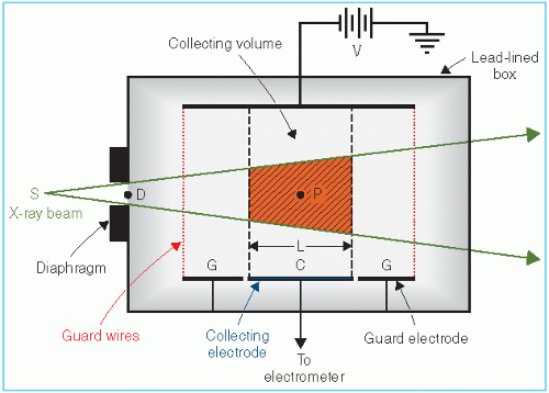 Figure 6.2. A schematic diagram of a free-air chamber. |
where AD is the diaphragm aperture area.
Accurate measurements with a free-air ionization chamber require considerable care. A few corrections that are usually applied include (a) correction for air attenuation; (b) correction for recombination of ions; (c) correction for the effects of temperature, pressure, and humidity on the density of air; and (d) correction for ionization produced by scattered photons. For details of various corrections, the reader is referred to National Bureau of Standards handbook (2).
There are limitations on the design of a free-air chamber for the measurement of roentgens for high-energy x-ray beams. As the photon energy increases, the range of the electrons liberated in air increases rapidly. This necessitates an increase in the separation of the plates to maintain electronic equilibrium. Too large a separation, however, creates problems of non-uniform electric field and greater ion recombination. Although the plate separation can be reduced by using air at high pressures, the problems still remain in regard to air attenuation, photon scatter, and reduction in the efficiency of ion collection. Because of these problems, there is an upper limit on the photon energy above which the roentgen cannot be accurately measured. This limit occurs at about 3 MeV.
6.4. THIMBLE CHAMBERS
Free-air ionization chambers are too delicate and bulky for routine use. Their main function is in the standardizing laboratories where they can be used to calibrate field instruments such as a thimble chamber.
The principle of the thimble chamber is illustrated in Figure 6.3. In Figure 6.3A, a spherical volume of air is shown with an air cavity at the center. Suppose this sphere of air is irradiated uniformly with a photon beam. Also, suppose that the distance between the outer sphere and the inner cavity is equal to the maximum range of electrons generated in air. If the number of electrons entering the cavity is the same as that leaving the cavity, electronic equilibrium exists. Suppose also that we are able to measure the ionization charge produced in the cavity by the electrons liberated in the air surrounding the cavity. Then, by knowing the volume or mass of air inside the cavity, we can calculate the charge per unit mass or the beam exposure at the center of the cavity. Now if the air wall in Figure 6.3A is compressed into a solid shell as in Figure 6.3B, we get a thimble chamber. Although the thimble wall is solid, it is air equivalent (i.e., its effective atomic number is the same as that of air). In addition, the thickness of the thimble wall is such
that the electronic equilibrium occurs inside the cavity, just as it did in Figure 6.3A. As before, it follows that the wall thickness must be equal to or greater than the maximum range of the electrons liberated in the thimble wall.
that the electronic equilibrium occurs inside the cavity, just as it did in Figure 6.3A. As before, it follows that the wall thickness must be equal to or greater than the maximum range of the electrons liberated in the thimble wall.
 Figure 6.3. Schematic diagram illustrating the nature of the thimble ionization chamber. A: Air shell with air cavity. B: Solid air shell with air cavity. C: The thimble chamber. |
Since the density of the solid air-equivalent wall is much greater than that of free air, the thicknesses required for electronic equilibrium in the thimble chamber are considerably reduced. For example, in the 100- to 250-kVp x-ray range, the wall thickness of the thimble (assuming unit density) is about 1 mm, and in the case of 60Co γ rays (average hv ≈ 1.25 MeV), it is approximately 5 mm. In practice, however, a thimble chamber is constructed with wall thicknesses of 1 mm or less, and this is supplemented with close-fitting caps of Plexiglas or other plastic to bring the total wall thickness up to that needed for electronic equilibrium for the radiation in question. These “build-up” caps are required when making measurements in free air.
A. CHAMBER WALL
Figure 6.3C shows a typical thimble ionization chamber. The wall is shaped like a sewing thimble—hence the name. The inner surface of the thimble wall is coated by a special material to make it electrically conducting. This forms one electrode. The other electrode is a rod of low-atomic-number material such as graphite or aluminum held in the center of the thimble but electrically insulated from it. A suitable voltage is applied between the two electrodes to collect the ions produced in the air cavity.
As mentioned previously, most of the ionization produced in the cavity air is caused by electrons that are liberated in the surrounding wall (for at least up to 2 MeV photons) and enter the air cavity. Therefore, in order for the thimble chamber to be equivalent to a free-air chamber, the thimble wall should be air equivalent. This condition would ensure that the energy spectrum of electrons liberated in the thimble wall is similar to that in air.
For the thimble chamber to be air equivalent, the effective atomic number of the wall material and the central electrode must be such that the system as a whole behaves like a free-air chamber. The most commonly used wall materials are made either of graphite (carbon), Bakelite, or a plastic coated on the inside by a conducting layer of graphite or of a conducting mixture of Bakelite and graphite. The effective atomic number of the wall is generally a little less than that of air. It is closer to that of carbon (Z = 6). As a consequence, such a wall should give rise to less ionization in the air cavity than a free-air wall. However, the usually greater atomic number of the central electrode, its dimensions, and the placement geometry within the thimble can provide compensation for the lower atomic number of the wall.
B. EFFECTIVE ATOMIC NUMBER
It is instructive to discuss the term effective atomic number ( ) in greater detail.
  is the atomic number of an element with which photons interact the same way as with the given composite material. Since photoelectric effect is highly Z dependent (Section 5.7),
  is considered for photoelectric interactions. Mayneord (3) has defined the effective atomic number of a compound as follows:
) in greater detail. is the atomic number of an element with which photons interact the same way as with the given composite material. Since photoelectric effect is highly Z dependent (Section 5.7), is considered for photoelectric interactions. Mayneord (3) has defined the effective atomic number of a compound as follows:
where a1, a2, a3, …, an are the fractional contributions of each element to the total number of electrons in the mixture.
Example 1. Calculation of  for Air
for AirComposition by weight: nitrogen 75.5%, oxygen 23.2%, and argon 1.3%
Number of electrons/g of air:  × (fraction by weight)
× (fraction by weight)
Total number of electrons/g of air = 3.01 × 10²³ (Table 5.1)
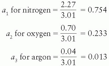
 = ((0.754) × 72.94 + (0.233) × 82.94 + (0.013) × 18)1/2.94 = 7.67
Since Mayneord’s work, other authors have proposed different values for the exponential dependences in computing the mean atomic number (i.e., values of m for a Zm in Equation 6.4). For example, the mean atomic numbers contained within Table 5.1 and Appendix A.7 were calculated by Johns and Cunningham (4) using m = 3.5.
C. CHAMBER CALIBRATION
A thimble chamber could be used directly to measure exposure if (a) it was air equivalent, (b) its cavity volume was accurately known, and (c) its wall thickness was sufficient to provide electronic equilibrium. Under the above conditions, the exposure X is given by
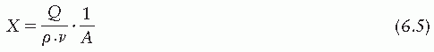
where Q is the ionization charge liberated in the cavity air of density p and volume v; A is the fraction of the energy fluence transmitted through the air-equivalent wall of equilibrium thickness. The factor A is slightly less than 1.00 and is used here to calculate the exposure for the energy fluence that would exist at the point of measurement in the absence of the chamber.
Related posts:


Stay updated, free articles. Join our Telegram channel

Full access? Get Clinical Tree


