Measurement of Absorbed Dose


Measurement of Absorbed Dose


8.1. DEFINITION OF ABSORBED DOSE

In Chapter 6, the quantity exposure and its unit, the roentgen (C/kg), were discussed. It was then pointed out that exposure applies only to x and γ radiations, is a measure of ionization in air only, and cannot be used for photon energies above about 3 MeV. The quantity absorbed dose has been defined to describe the quantity of radiation for all types of ionizing radiation, including charged and uncharged particles; all materials; and all energies. Absorbed dose is a measure of the biologically significant effects produced by ionizing radiation.

The current definition of absorbed dose, or simply dose, is the quotient image where image is the mean energy imparted by ionizing radiation to material of mass dm (1). The old unit of dose is rad (an acronym for radiation absorbed dose) and represents the absorption of 100 ergs of energy per gram of absorbing material:


The SI unit for absorbed dose is gray (Gy) and is defined as


Thus, the relationship between gray, centigray (cGy), and rad is


or


8.2. RELATIONSHIP BETWEEN KERMA, EXPOSURE, AND ABSORBED DOSE


A. KERMA

The quantity kerma (K) (kinetic energy released in the medium) is defined as “the quotient of dEtr by dm, where dEtr is the sum of the initial kinetic energies of all the charged ionizing particles (electrons and positrons) liberated by uncharged particles (photons) in a material of mass dm” (1).


The unit for kerma is the same as for dose, that is, J/kg. The name of its SI unit is gray (Gy).

For a photon beam traversing a medium, kerma at a point is directly proportional to the photon energy fluence Ψ and is given by


where image 
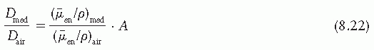
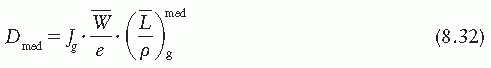
is the mass energy transfer coefficient for the medium averaged over the energy fluence spectrum of photons. As discussed in Section 5.4,


where image
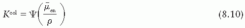
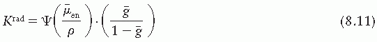
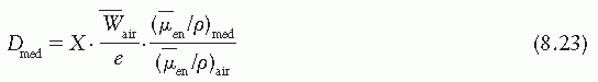
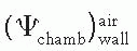
/ρ is the averaged mass energy absorption coefficient and image is the average fraction of an electron energy lost to radiative processes. Therefore,


A major part of the initial kinetic energy of electrons in low-atomic-number materials (e.g., air, water, soft tissue) is expended by inelastic collisions (ionization and excitation) with atomic electrons. Only a small part is expended in the radiative collisions with atomic nuclei (bremsstrahlung). Kerma can thus be divided into two parts:


where Kcol and Krad are the collision and the radiative parts of kerma, respectively. From Equations 8.8 and 8.9,


and


B. EXPOSURE AND KERMA

In Chapter 6, the quantity exposure was defined as dQ/dm where dQ is the total charge of the ions of one sign produced in air when all the electrons (negatrons and positrons) liberated by photons in (dry) air of mass dm are completely stopped in air.

Exposure is the ionization equivalent of the collision kerma in air. It can be calculated from Kcol by knowing the ionization charge produced per unit of energy deposited by photons. The mean energy required to produce an ion pair in dry air is almost constant for all electron energies and has a value of image 
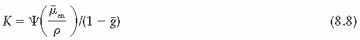
= 33.97 eV/ion pair (2). If e is the electronic charge (= 1.602 × 10⁻¹⁹ C), then image is the average energy required per unit charge of ionization produced. Since 1 eV = 1.602 × 10⁻¹⁹ J, image = 33.97 J/C. Exposure (X) is given by


C. ABSORBED DOSE AND KERMA

The relationship between absorbed dose (D) and the collision part of kerma (Kcol) is illustrated in Figure 8.1 when a broad beam of photons enters a medium. Whereas kerma is maximum at the surface and decreases with depth, the dose initially builds up to a maximum value and then decreases at the same rate as kerma. Before the two curves meet, the electron buildup is less than complete, and


where β is the quotient of absorbed dose at a given point and the collision part of kerma at the same point.

Because of the increasing range of the electrons, complete electronic equilibrium does not exist within megavoltage photon beams. However, conceptually electronic equilibrium would exist if it were assumed that photon attenuation is negligible throughout the region of interest. Then


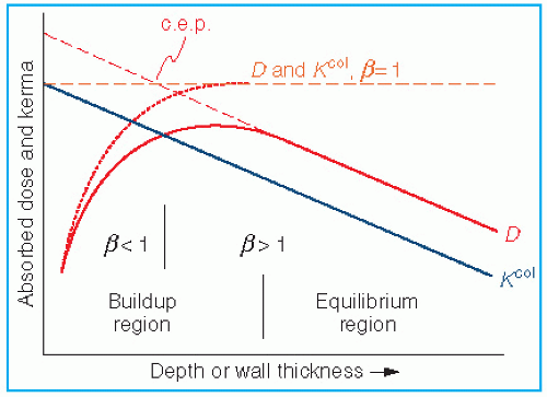
Figure 8.1. Relationship between absorbed dose (D) and collision kerma (Kcol) for a megavoltage photon beam. β is the ratio of absorbed dose to collision kerma. The point designated as c.e.p. is the center of electron production (see text). (From Loevinger R. A formalism for calculation of absorbed dose to a medium from photon and electron beams. Med Phys. 1981;8:1, with permission.)


At depths greater than the maximum range of electrons, there is a region of quasie-quilibrium called the transient electron equilibrium in which


In the transient equilibrium region, β is greater than unity because of the combined effect of attenuation of the photon beam and the predominantly forward motion of the electrons. Because the dose is being deposited by electrons originating upstream, one can think of a point somewhere upstream at a distance less than the maximum electron range from where the energy is effectively transported by secondary electrons. This point has been called the “center of electron production” (3). Since the center of electron production is located upstream relative to the point of interest, the dose is greater than kerma in the region of transient electronic equilibrium.

The relationship between absorbed dose and photon energy fluence Ψ at a point is given by


Suppose D1 is the dose at a point in some material in a photon beam and another material is substituted of a thickness of at least one maximum electron range in all directions from the point; then D2, the dose in the second material, is related to D1 by


The factor β has been calculated for 60Co and other photon energies for air, water, polystyrene, carbon, and aluminum (4,5). The results show that the value of β varies with energy, not medium. A fixed value of β = 1.005 has been used for 60Co in conjunction with ion chamber dosimetry (6).

For further details of the relationship between absorbed dose and kerma and its significance in dosimetry, the reader is referred to a paper by Loevinger (4).


8.3. CALCULATION OF ABSORBED DOSE FROM EXPOSURE


A. ABSORBED DOSE TO AIR

Determination of absorbed dose from exposure is readily accomplished under conditions of electron equilibrium. However, for energies in the megavoltage range, the electron fluence producing absorbed dose at a point is characteristic of photon energy fluence some distance upstream. Consequently, there may be appreciable photon attenuation in this distance. The calculation of absorbed dose from exposure when rigorous electronic equilibrium does not exist is much more difficult, requiring energy-dependent corrections. Therefore, the determination of exposure and its conversion to absorbed dose is practically limited to photon energies up to 60Co. In the presence of charged particle equilibrium (CPE), the dose at a point in any medium is equal to the collision part of kerma; that is, β = 1. Dose to air (Dair) under these conditions is given by (see Equation 8.12)


Inserting units:


Since 1 cGy = 10−2 J/kg,


From Equation 8.20, it is seen that the conversion factor from roentgen to cGy for air, under the conditions of electronic equilibrium, is 0.876.


B. ABSORBED DOSE TO ANY MEDIUM

In the presence of full CPE (i.e., β = 1 in Equation 8.17), the absorbed dose (D) to a medium can be calculated from the energy fluence Ψ and the weighted mean mass energy absorption coefficient, image:


Suppose Ψair is the energy fluence at a point in air and Ψmed is the energy fluence at the same point when a material other than air (medium) is interposed in the beam. Then, under conditions of electronic equilibrium in either case, the dose to air is related to the dose to the medium by the following relationship:


where A is a transmission factor that equals the ratio Ψmedair at the point of interest.

From Equations 8.19 and 8.22, we obtain the relationship between exposure to air and absorbed dose to a medium:


Again, if X is in roentgens and Dmed is in cGy, we have


The quantity in brackets has frequently been represented by the symbol fmed so that


where


The quantity fmed or simply the f factor is sometimes called the roentgen-to-rad conversion factor. As the above equation suggests, this factor depends on the mass energy absorption coefficient of the medium relative to the air. Thus, the f factor is a function of the medium composition as well as the photon energy.

A list of f factors for water, bone, and muscle as a function of photon energy is given in Table 8.1. Since for materials with an atomic number close to that of air, for example, water and soft tissue, the ratio image varies slowly with photon energy (˜10% variation from 10 keV and 10 MeV), the f factor for these materials does not vary much over practically the whole therapeutic range of energies. However, bone with a high effective atomic number not only has a much larger f factor between 10 and 100 keV, but also the f factor drops sharply from its maximum value of 4.24 at 30 keV to about 1.0 at 175 keV. This high peak value and rapid drop of the f factor are the result of the photoelectric process for which the mass energy absorption coefficient varies approximately as Z3 and 1/E3 (see Chapter 5). At higher photon energies where the Compton process is the predominant mode of interaction, the f factors are approximately the same for all materials.

Strictly speaking, in the Compton range of energies, the f factor varies as a function of the number of electrons per gram. Since the number of electrons per gram for bone is slightly less than for air, water, or fat, the f factor for bone is also slightly lower than for the latter materials in the Compton region of the megavoltage energies. Of course, the f factor is not defined beyond 3 MeV since the roentgen is not defined beyond this energy.


C. DOSE CALIBRATION WITH ION CHAMBER IN AIR

As discussed in Chapter 6, a cavity ion chamber is exposure calibrated against a free-air ion chamber or a standard cavity chamber, under conditions of electronic equilibrium. For lower-energy radiations such as x-ray beams in the superficial or orthovoltage range, the chamber walls are usually thick enough to provide the desired equilibrium, and therefore, the chamber calibration is provided without a buildup cap. However, in the case of higher-energy radiations such as from cobalt-60, a buildup cap is used over the sensitive volume of the chamber so that the combined thickness of the chamber wall and the buildup cap is sufficient to provide the required equilibrium. This buildup cap is usually made up of acrylic (same as Plexiglas, Lucite, or Perspex) and must be in place when measuring exposure.

Suppose the chamber is exposed to the beam (Fig. 8.2A) and the reading M is obtained (corrected for air temperature and pressure, stem leakage, collection efficiency, etc.). The exposure X is then given by


where Nx is the exposure calibration factor for the given chamber and the given beam quality. The exposure thus obtained is the exposure at point P (center of the chamber-sensitive volume)
in free air in the absence of the chamber (Fig. 8.2B). In other words, the perturbing influence of the chamber is removed once the chamber calibration factor is applied.


TABLE 8.1 f Factors for Water, Bone, and Muscle under Conditions of Charged Particle Equilibrium


f Factor


Photon


Water


Bone


Muscle


Energy (keV)


(Gy kg/C)


(rad/R)


(Gy kg/C)


(rad/R)


(Gy kg/C)


(rad/R)


10


35.3


0.911


134


3.46


35.7


0.921


15


34.9


0.900


149


3.85


35.7


0.921


20


34.6


0.892


158


4.07


35.6


0.919


30


34.3


0.884


164


4.24


35.6


0.918


40


34.4


0.887


156


4.03


35.7


0.922


50


34.9


0.900


136


3.52


36.0


0.929


60


35.5


0.916


112


2.90


36.3


0.937


80


36.5


0.942


75.1


1.94


36.8


0.949


100


37.1


0.956


56.2


1.45


37.1


0.956


150


37.5


0.967


41.2


1.06


37.2


0.960


200


37.6


0.969


37.9


0.978


37.2


0.961


300


37.6


0.970


36.5


0.941


37.3


0.962


400


37.6


0.971


36.2


0.933


37.3


0.962


600


37.6


0.971


36.0


0.928


37.3


0.962


1,000


37.6


0.971


35.9


0.927


37.3


0.962


2,000


37.6


0.971


35.9


0.927


37.3


0.962


(Data from Wyckoff HO. (Communication.) Med Phys. 1983;10:715. Calculations are based on energy absorption coefficient data from Hubbell JH. Photon mass attenuation and energy-absorption coefficients from 1 keV to 20 MeV. Int J Appl Radiat Isot. 1982;33:1269.)


Consider a small amount of soft tissue at point P that is just large enough to provide electronic equilibrium at its center (Fig. 8.2C). The dose at the center of this equilibrium mass of tissue is referred to as the dose in free space. The term “dose in free space” was introduced by Johns and Cunningham (7), who related this quantity to the dose in an extended tissue medium by means of tissue-air ratios (to be discussed in Chapter 9).

Equation 8.25 can be used to convert exposure into dose in free space, Df.s.:


where Aeq is the transmission factor representing the ratio of the energy fluence at the center of the equilibrium mass of tissue to that in free air at the same point. Thus, Aeq represents the ratio of the energy fluence at point P in Figure 8.2C to that at the same point in Figure 8.2B. For cobalt-60 beam, Aeq is close to 0.99 (7) and its value approaches 1.00 as the beam energy decreases to the orthovoltage range.


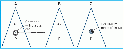
Figure 8.2. A: Chamber with buildup cap is placed in a radiation beam at point P in air and reading M is obtained. B: Exposure in free air at P is calculated using Equation 8.27. C: Dose in free space at P is calculated using Equation 8.28.


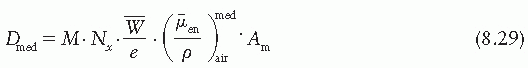
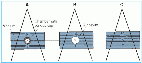
Figure 8.3. A: Chamber with buildup cap with its center at point P in a medium, exposed to a photon beam whose energy fluence is Ψb at P. Reading M is obtained. B: Exposure at P in air cavity of size equal to the external dimensions of the buildup cap is calculated. Energy fluence at P is Ψc. C: Absorbed dose at point P in the medium is calculated by Equation 8.29. Ψm is the energy fluence at P.


D. DOSE MEASUREMENT FROM EXPOSURE WITH ION CHAMBER IN A MEDIUM

Equations 8.27 and 8.28 provide the basis for absorbed dose calculation in any medium from exposure measurement in air. A similar procedure is valid when the exposure measurement is made with the chamber imbedded in a medium. Figure 8.3A shows an arrangement in which the chamber with its buildup cap is surrounded by the medium and exposed to a photon energy fluence Ψb at the center of the chamber (point P). If the energy of the beam incident on the chamber is such that a state of electronic equilibrium exists within the air cavity, then the exposure at point P, with the chamber and the buildup cap removed, is given by

X = M · Nx

The exposure thus measured is defined in free air at point P due to energy fluence Ψc that would exist at P in the air-filled cavity of the size equal to the external dimensions of the buildup cap (Fig. 8.3B). To convert this exposure to absorbed dose at P in the medium, the air in the cavity must be replaced by the medium (Fig. 8.3C) and the following equation is applied:

Dmed = X · fmed · Am

or


where Am is the transmission factor for the photon energy fluence at point P when the cavity in Figure 8.3B is replaced by the medium. If Ψm is the energy fluence at P in the medium, the factor Am is given by Ψmc. Am has been called the displacement factor.

The above equation is similar to Equation 8.28 except that Am is used instead of Aeq. However, the difference between Am and Aeq is small for a tissue equivalent medium since the equilibrium mass of tissue to which Aeq applies is only slightly smaller than the mass of the medium displaced by a typical small ion chamber with its buildup cap.

An interesting question arises in regard to the necessity of the buildup cap being left on the chamber when making measurements in a medium such as water. If the chamber has been calibrated for exposure in air with its buildup cap on (to achieve electronic equilibrium) and if a significant part of the cavity ionization is the result of electrons produced in the buildup cap, then replacing the buildup cap with the medium could alter the chamber reading. This substitution of a layer of medium for the buildup cap could change the electronic and photon fluence incident on the chamber wall by virtue of differences in the composition of the medium and the material of the buildup cap. However, in practical calibration measurements, no significant differences have been observed when exposing the chamber in water with and without the acrylic buildup cap. Day et al. (8) added Perspex sheaths up to 5 mm in thickness to a Baldwin-Farmer ionization chamber irradiated at a depth of 5 cm in a water phantom using radiations from 137Cs to 6 MV. The readings differed only by less than 0.5%.


8.4. THE BRAGG-GRAY CAVITY THEORY

As discussed earlier, calculation of absorbed dose from exposure is subject to some major limitations. For instance, it may not be used for photons above 3 MeV and may not be used in cases
where electronic equilibrium does not exist. In addition, the term exposure applies only to x and γ radiations and for that reason methods of Section 8.3 are not valid for particle dosimetry. The Bragg-Gray cavity theory, on the other hand, may be used without such restrictions to calculate dose directly from ion chamber measurements in a medium.

According to the Bragg-Gray theory (9,10), the ionization produced in a gas-filled cavity placed in a medium is related to the energy absorbed in the surrounding medium (e.g., Figure 8.3B with an air cavity embedded in a medium). When the cavity is sufficiently small so that its introduction into the medium does not alter the number or distribution of the electrons that would exist in the medium without the cavity, then the following Bragg-Gray relationship is satisfied:


where Dmed is the absorbed dose in the medium (in the absence of the cavity), Jg is the ionization charge of one sign produced per unit mass of the cavity gas, and image 
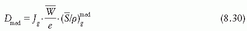
is a weighted mean ratio of the mass stopping power of the medium to that of the gas for the electrons crossing the cavity. The product of Jg (image) is the energy absorbed per unit mass of the cavity gas.

The basic Bragg-Gray relationship has been carefully examined by many investigators and several modifications of the theory have been proposed (11, 12, 13, 14). These refinements resulted in more detailed considerations of what is appropriate to use for the mass stopping power ratio in Equation 8.30.


A. STOPPING POWER

The term stopping power refers to the energy loss by electrons per unit path length of a material (for greater details, see Section 14.1). An extensive set of calculated values of mass stopping powers has been published (15,16). As mentioned earlier, to use stopping power ratios in the Bragg-Gray formula, it is necessary to determine a weighted mean of the stopping power ratios for the electron spectrum set in motion by the photon spectrum in the materials concerned. Methods for calculating average stopping powers (S) for photon beams have been published (17). Several authors have worked out the theory of the stopping power ratio for an air-filled cavity in a medium such as water under electron irradiation. A good approximation is provided by the Spencer-Attix formulation (11,18), which uses a restricted mass stopping power in Equation 8.30, defined as


where Φ(E) is the distribution of electron fluence in energy and L/ρ is the restricted mass collision stopping power with Δ as the cutoff energy.

The “primary electrons” (original electrons or electrons generated by photons) give rise to ionization as well as “secondary electrons” or σ rays. The effects of the latter are accounted for in the Spencer-Attix formulation by using an arbitrary energy limit, Δ, below which energy transfers are considered dissipative; that is, the secondary electron of energy less than Δ is assumed to dissipate its energy near the site of its release. Thus, when the integration is performed (Equation 8.31) to obtain the energy deposited in the cavity by the electron fluence, the lower energy limit should be Δ, greater than zero. For ion chambers it must have a value of the order of the energy of an electron that will just cross the cavity. The value of Δ for most cavity applications in ion chambers will lie between 10 and 20 keV.

The Spencer-Attix formulation of the Bragg-Gray cavity theory uses the following relationship:


where image 
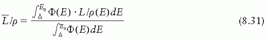
is the average restricted mass collisional stopping power of electrons. Tables A.1, A.2, A.3, A.4 and A.5 in the Appendix give image for various media and various photon and electron energies.


B. CHAMBER VOLUME

The quantity Jg in Equation 8.32 can be determined for a chamber of known volume or known mass of air in the cavity if the chamber is connected to a charge-measuring device. However, the chamber volume is usually not known to an acceptable accuracy. An indirect method of measuring Jair is to make use of the exposure calibration of the chamber for 60Co γ-ray beam. This in effect determines the chamber volume.


Consider an ion chamber that has been calibrated with a buildup cap for 60Co exposure. Suppose the chamber with this buildup cap is exposed in free air to a 60Co beam and that a transient electronic equilibrium exists at the center of the chamber. Also assume initially that the chamber wall and the buildup cap are composed of the same material (wall). Now, if the chamber (plus the buildup cap) is replaced by a homogeneous mass of wall material with outer dimensions equal to that of the cap, the dose Dwall at the center of this mass can be calculated as follows:


where image 
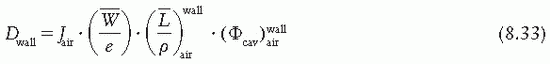
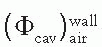
is the ratio of electron fluence at the reference point P (center of the cavity) with chamber cavity filled with wall material to that with the cavity filled with air. This correction is applied to the Bragg-Gray relation (Equation 8.29) to account for change in electron fluence.

As discussed by Loevinger (4),1 Φ in the above equation can be replaced by Ψ, provided a transient electron equilibrium exists throughout the region of the wall from which secondary electrons can reach the cavity. Therefore,


If Dair is the absorbed dose to air that would exist at the reference point with the chamber removed and under conditions of transient electronic equilibrium in air, we get from Equation 8.18:


where image 
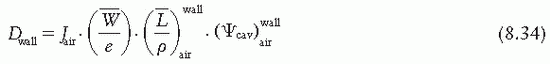
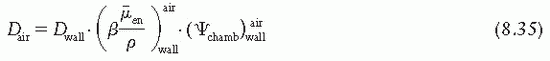
is the ratio that corrects for the change in photon energy fluence when air replaces the chamber (wall plus cap).

From Equations 8.34 and 8.35, we get


Also, Dair (under conditions of transient electronic equilibrium in air) can be calculated from exposure measurement in a 60Co beam with a chamber plus buildup cap, which bears an exposure calibration factor Nx for 60Co γ rays:


where k is the charge per unit mass produced in air per unit exposure (2.58 × 10⁻⁴ C/kg/R), M is the chamber reading (C or scale division) normalized to standard atmospheric conditions, Aion is the correction for ionization recombination under calibration conditions, and Pion is the ionization recombination correction for the present measurement.

Standard conditions for Nx are defined by the standards laboratories. The National Institute of Standards and Technology (NIST) specifies standard conditions as temperature at 22°C and pressure at 760 mmHg. Since exposure is defined for dry air, humidity correction of 0.997 (for change in image 
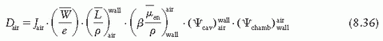
with humidity) is used by the NIST, which can be assumed constant in the relative humidity range of 10% to 90% for the measurement conditions with minimal error (19). Thus, the user does not need to apply additional humidity correction as long as it is used for dry air.


The product image
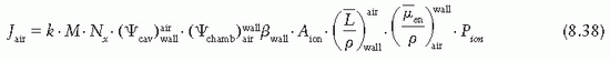
, which represents a correction for the change in Jair due to attenuation and scattering of photons in the chamber wall and buildup cap. This factor has been designated as Awall in the American Association of Physicists in Medicine (AAPM) protocol (6). Thus, Equation 8.38 becomes


Now consider a more realistic situation in which the chamber wall and buildup cap are of different materials. According to the two-component model of Almond and Svensson (20), let α be
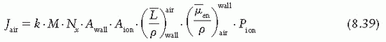
the fraction of cavity air ionization owing to electrons generated in the wall and the remaining (1 – α) from the buildup cap. Equation 8.39 can now be written as


or

Jair = k · M · Nx · Awall · βwall · Aion · Aα · Pion

where Aα is the quantity in the brackets of Equation 8.40.

The fraction α has been determined experimentally by dose buildup measurements for various wall thicknesses (Fig. 8.4). In addition, it has been shown (21) that α is independent of wall composition or buildup cap, as long as it is composed of low-atomic-number material.

Since Jair is the charge produced per unit mass of the cavity air, we have


where Vc is the chamber volume and ρair is the density of air normalized to standard conditions. Comparing Equations 8.40 and 8.41, we have


C. EFFECTIVE POINT OF MEASUREMENT


C.1. Plane-Parallel Chambers

Since the front plane (toward the source) of the air cavity is flat and is exposed to a uniform fluence of electrons, the point of measurement is at the front surface of the cavity. This would be strictly true if the electrons were monodirectional and forward directed, perpendicular to the cavity face. If a significant part of the cavity ionization is caused by back-scattered electrons, the point of measurement will shift toward the center. If the plane-parallel chamber has a small plate separation and the electron fluence is mostly forward directed, it is reasonable to assume that the point of measurement is the front surface of the cavity.


C.2. Cylindrical Chambers

Electrons (from an electron beam or generated by photons) transversing a cylindrical chamber of internal radius γ will enter the sensitive volume of the chamber (air cavity) at different distances from the center of the chamber. Dutreix and Dutreix (22) showed that theoretically the point of measurement for a cylindrical chamber in a unidirectional beam is displaced by 0.85γ from the center and toward the source. Derivation of this value is instructive in understanding the concept and is, therefore, presented here.

Figure 8.5 shows a cross section of a cylindrical chamber exposed to a parallel, uniform, and forwardly directed fluence Φ of electrons. For an electron entering the chamber at point A, the
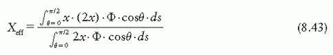
point of measurement is at a distance X above the center. Considering electrons entering the chamber at point A, the effective point of measurement is influenced by the number of electrons entering through a surface area ds at A of the chamber and the track length of these electrons in the cavity. Thus, the effective point of measurement, Xeff, can be determined by weighting the displacement X by the number of electrons (Φ · ds cos θ) entering the chamber and the track length (2X):


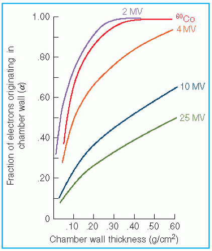
Figure 8.4. The fraction, α, of cavity ionization due to electrons generated in the chamber wall, plotted as a function of wall thickness. (From Lempert GD, Nath R, Schulz RJ. Fraction of ionization from electrons arising in the wall of an ionization chamber. Med Phys. 1983;10:1, with permission.)


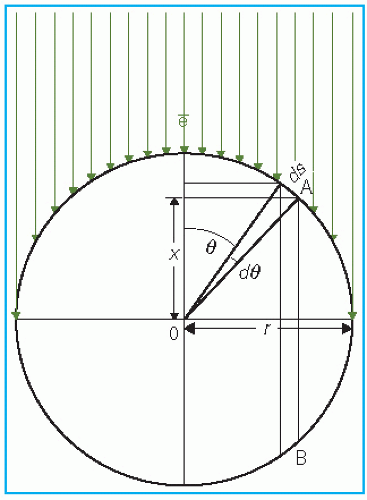
Figure 8.5. Diagram to illustrate the determination of effective point of measurement for a cylindrical chamber exposed to a unidirectional electron beam.


Substituting X = r cos θ and ds = rdθ,


The above theoretical result is modified under actual irradiation conditions as some of the electrons enter the chamber at oblique angles.

The shift in the point of measurement takes place because of the cylindricality of the chamber cavity. If there is a gradient of electron fluence across the cavity (as in the exponential falloff of the depth-dose curve), a shift in the point of measurement will result in a “gradient correction” to the dose measured at a point corresponding to the center of the chamber (to be discussed).


1Electron fluence at P with the cavity filled with wall material is proportional to Ψwall at P. With the air cavity in place, the electron fluence at P is proportional to the mean photon energy fluence at the surface of the cavity, which can be taken as equal to Ψair at the center of the cavity.


8.5. CALIBRATION OF MEGAVOLTAGE BEAMS: TG-51 PROTOCOL

The AAPM and International Atomic Energy Agency (IAEA) periodically publish standard protocols for linear accelerator dose calibration protocols. In 1983, AAPM Task Group 21 (TG-21) published an absorbed dose calibration protocol (6) using an ion chamber calibrated with an exposure calibration factor, NX, in a 60Co beam. TG-21 introduced a factor Ngas to represent calibration of the cavity gas in terms of absorbed dose to the gas in the chamber per unit charge or electrometer reading. For photon beams, the equation for dose to the medium (Dmed) is given by the Bragg-Gray relationship using the Spencer-Attix formulation:


where M is the charge measured, Pion is a correction factor for ion recombination losses, Prepl is a replacement factor that corrects for perturbation in the electron and photon fluences at point P as a result of insertion of the cavity in the medium, and Pwall is a factor that accounts for perturbation caused by the wall being different from the medium. For electron beams, the equation for Dmed within the TG-21 protocol was as follows:


where image 
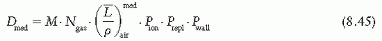
is the mean energy of the electron beam and Prepl is a replacement correction factor to account for three effects: (a) the in-scatter effect, which increases the fluence in the cavity since electron scattering out of the cavity is less than that expected in the intact medium; (b) the obliquity effect, which decreases the fluence in the cavity because electrons travel relatively straight in the cavity instead of taking oblique paths as they would owing to larger-angle scattering in the medium; and (c) displacement in the effective point of measurement, which gives rise to a correction if the point of measurement is on the sloping part of the depth-dose curve.

In 1999, AAPM Task Group 51 (TG-51) published a new calibration protocol for photon and electron beams. The TG-51 protocol (23) represents a major upgrade of the TG-21 protocol in several respects: (a) it is based on absorbed dose-to-water calibration factor, image, instead of exposure or air kerma calibration of the ion chamber; (b) the user does not need to calculate any theoretical dosimetry factors; and (c) large tables of stopping-power ratios and mass energy absorption coefficients are not needed. Although the adoption of TG-51 results in only modest improvement in dosimetric accuracy over the TG-21 protocol (1% to 2%), the gain in simplicity is a significant factor from the user’s point of view.

Only gold members can continue reading. Log In or Register to continue

Stay updated, free articles. Join our Telegram channel

Jun 8, 2016 | Posted by in GENERAL RADIOLOGY | Comments Off on Measurement of Absorbed Dose

Full access? Get Clinical Tree

Get Clinical Tree app for offline access