Low-Dose-Rate Brachytherapy: Rules of Implantation and Dose Specification
Brachytherapy is a method of treatment in which sealed radioactive sources are used to deliver radiation at a short distance by interstitial, intracavitary, or surface application. With this mode of therapy, a high radiation dose can be delivered locally to the tumor with rapid dose falloff in the surrounding normal tissue. In the past, brachytherapy was carried out mostly with radium or radon sources. Currently, use of artificially produced radionuclides such as 137Cs, 192Ir, 198Au, 125I, and 103Pd is more common.
Technical developments in the last few decades have stimulated increased interest in brachytherapy: the introduction of low-energy sources, afterloading devices to reduce personnel exposure, and automatic devices with remote control to deliver controlled radiation exposure from high-activity sources. Although electrons are often used as an alternative to interstitial implants, brachytherapy continues to remain an important mode of therapy, either alone or combined with external beam.
15.1. RADIOACTIVE SOURCES
From the time of its discovery in 1898, radium has been the most commonly used isotope in brachytherapy. However, artificial radioisotopes offer special advantages in some situations because of their γ-ray energy, source flexibility, source size, and half-life. Table 15.1 lists some of the brachytherapy sources that have been or are currently being used with their relevant physical properties.
A. RADIUM
Although radium is no longer clinically used in brachytherapy, the physics of this source is discussed below for historic interest. Also, a vast amount of clinical data pertaining to radium therapy exist in the literature which are often used by clinicians to compare treatment outcomes and dosage specification in modern brachytherapy.
A.1. Decay
Radium is the sixth member of the uranium series, which starts with  and ends with stable
  (Fig. 2.3). Radium disintegrates with a half-life of about 1,600 years to form radon:
and ends with stable (Fig. 2.3). Radium disintegrates with a half-life of about 1,600 years to form radon: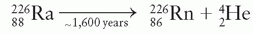
The product nucleus radon is a heavy inert gas that in turn disintegrates into its daughter products as shown in Figure 2.3. As a result of the decay process from radium to stable lead, at least 49 γ rays are produced with energies ranging from 0.184 to 2.45 MeV. The average energy of the γ rays from radium in equilibrium with its daughter products and filtered by 0.5 mm of platinum is 0.83 MeV (1). A filtration of at least 0.5 mm platinum provided by the source case is sufficient to absorb all α particles and most of the β particles emitted by radium and its daughter products. Only γ rays are used for therapy.
TABLE 15.1 Physical Characteristics of Radionuclides Used in Brachytherapy | ||||||||||||||||||||||||||||||||||||||||||||||||||
|---|---|---|---|---|---|---|---|---|---|---|---|---|---|---|---|---|---|---|---|---|---|---|---|---|---|---|---|---|---|---|---|---|---|---|---|---|---|---|---|---|---|---|---|---|---|---|---|---|---|---|
| ||||||||||||||||||||||||||||||||||||||||||||||||||
Because the half-life for radioactive decay is much greater for 226Ra than for any of its daughter products, radium, when placed in a sealed container, achieves a secular equilibrium with its daughters (Fig. 2.5). The time required to establish equilibrium is approximately 1 month from the time of encapsulation.
A.2. Source Construction
Radium is supplied mostly in the form of radium sulfate or radium chloride that is mixed with an inert filler and loaded into cells about 1 cm long and 1 mm in diameter. These cells are made of 0.1- to 0.2-mm-thick gold foil and are sealed to prevent leakage of radon gas. The sealed cells are then loaded into the platinum sheath, which in turn is sealed. Radium sources are manufactured as needles or tubes in a variety of lengths and activities (Fig. 15.1).
A.3. Source Specification
Radium sources are specified by (a) active length, the distance between the ends of the radioactive material; (b) physical length, the distance between the actual ends of the source; (c) activity or strength of source, milligrams of radium content; and (d) filtration, transverse thickness of the capsule wall, usually expressed in terms of millimeters of platinum. Linear activity of a source can be determined by dividing the activity by the active length. Figure 15.1 illustrates three types of radium needles used for implants: needles of uniform linear activity, needles with higher activity at one end (Indian club), and needles with high activity at both ends (dumbbell). Uniform linear activity needles may be “full intensity” (0.66 mg/cm) or “half intensity” (0.33 mg/cm). Needles also are constructed with linear activities of 0.5 and 0.25 mg/cm. Tubes for intracavitary and mold therapy are usually furnished in multiples of 5 mg of radium filtered by 1 mm platinum.
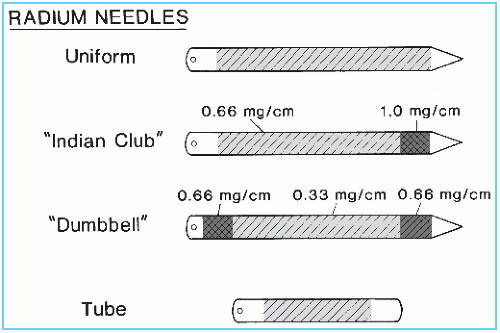 Figure 15.1. Types of radium sources used in interstitial and intracavitary therapy. |
To test the uniformity of activity distribution, an autoradiograph is obtained by placing the source on an unexposed x-ray film for a time long enough to obtain reasonable darkening of the film. The source may be radiographed at the same time to show physical dimensions of the source superimposed on the autoradiograph. Figure 15.2 shows an autoradiograph obtained in this manner. The exposed film may be scanned with a densitometer to obtain optical density distribution. Uniformity of activity distribution can thus be assessed from such a distribution.
A.4. Exposure Rate Constant1
The activity of a radioactive nuclide emitting photons is related to the exposure rate by the exposure rate constant, Γδ (see Section 8.7 for derivation). In brachytherapy, this constant is usually expressed as numerically equal to the exposure rate in R/h at a point 1 cm from a 1-mCi point source. In the case of radium, the source strength is specified in terms of milligrams of radium instead of mCi.
The International Commission on Radiation Units and Measurements (ICRU) (4) has recommended that Γδ for radium filtered by 0.5 mm platinum be taken as 8.25 R-cm2/h/mg. Table 15.2 gives Γδ factors for radium with other filtrations. These values are based on relative transmission measurements versus platinum thickness (5) and normalized to Γδ = 8.25 for 0.5 mm platinum.
A.5. Radon Hazard
Leakage of radon gas from a radium source represents a significant hazard if the source is broken. The sources are, however, doubly encapsulated to prevent such an occurrence. Spontaneous rupture of a sealed radium source due to pressure buildup of helium gas (from α-particle disintegrations) is considered unlikely. Van Roosenbeek et al. (6) have calculated that sources encapsulated in platinum may remain safely sealed for more than 400 years.
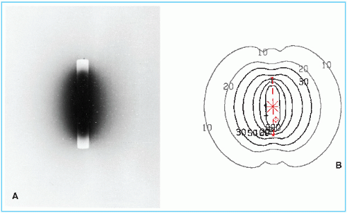 Figure 15.2. An autoradiograph of a cesium-137 tube. Isodose curves are shown for the same source in the diagram on the right. |
TABLE 15.2 Exposure Rate Constant for Radium Point Source Filtered by Various Thicknesses of Platinum | ||||||||||||||||||||||
|---|---|---|---|---|---|---|---|---|---|---|---|---|---|---|---|---|---|---|---|---|---|---|
| ||||||||||||||||||||||
B. CESIUM-137
Cesium-137 is a γ-ray-emitting radioisotope that is used as a radium substitute in both interstitial and intracavitary brachytherapy. It is supplied in the form of insoluble powders or ceramic microspheres, labeled with 137Cs, and doubly encapsulated in stainless steel needles and tubes. The advantages of 137Cs over radium are that it requires less shielding (compare half-value layers in Table 15.1) and is less hazardous in the microsphere form. With a long half-life of about 30 years, these sources can be used clinically for about 7 years without replacement, although the treatment times have to be adjusted to allow for radioactive decay (2% per year).
137Cs emits γ rays of energy 0.662 MeV. The decay scheme shows that 137Cs transforms to 137Ba by the process of β− decay but 93.5% of the disintegrations are followed by γ rays from the 137Ba metastable state. The β particles and low-energy characteristic x-rays are absorbed by the stainless steel material, so that the clinical source is a pure γ emitter.
It should be emphasized that Γδ is defined in terms of an ideal point source. Any practical source will have a finite size and would necessitate corrections for photon attenuation and scattering. The γ rays from cesium have nearly the same penetrating power as radium γ rays in tissue. Meisberger et al. (7) have compared the measured and calculated depth dose values along the transverse axes of the sources and showed that the exposure in water to exposure in air ratio is the same for radium and cesium for depths up to 10 cm. Significant differences, however, exist between radium and cesium doses at points along oblique angles (near the longitudinal axis) due to the filtration effect (8,9). Not only the attenuation of γ rays in steel and platinum is quite different, but also cesium emits monoenergetic γ rays, while radium emits γ rays of wide energy range.
The exposure rate constant Γδ for unfiltered 137Cs is 3.26 Rcm2 mCi-1 h-1 (10). Comparing this with the Γδ of 8.25 R-cm2/mg/h for radium filtered by 0.5 mm Pt, the conversion factor is 8.25/3.26 = 2.53 mCi of 137Cs/mg of 226Ra. However, along the transverse axes of clinical sources (cesium with 0.5-mm steel and radium with 0.5-mm Pt filtration), the mean conversion factor has been calculated to be 2.55 for cesium needles and 2.59 for cesium tubes (9).
C. COBALT-60
60Co has been used for brachytherapy but is no longer used now. The main advantage of 60Co is its high specific activity, which allows fabrication of small sources required for some special applicators. However, it is more expensive than 137Cs and has a short half-life (5.26 years), necessitating more frequent replacement and a complex inventory system.
Cobalt brachytherapy sources are usually fabricated in the form of a wire that is encapsulated in a sheath of platinum iridium or stainless steel. The sources can be used to replace 226Ra in intracavitary applications. Curie-sized cobalt sources have also been used in a unit called the Cathetron (11, 12, 13). This is a remote-loading device and provides high dose rates for intracavitary therapy, for example, 250 to 300 cGy/min at point “A” (see Section 15.7B for definition of point A).
D. IRIDIUM-192
Iridium-192 (alloy of 30% Ir and 70% Pt) sources are fabricated in the form of thin flexible wires that can be cut to desired lengths. Nylon ribbons containing iridium seeds 3 mm long and 0.5 mm in diameter, spaced with their centers 1 cm apart, are also commonly used. Both the wires and the seed ribbons are quite suitable for the afterloading technique (14,15) (see Section 15.6B).
192Ir has a complicated γ-ray spectrum with an average energy of 0.38 MeV. Because of the lower energy, these sources require less shielding for personnel protection (compare half-value layers in Table 15.1). 192Ir has the disadvantage of a short half-life (73.8 days). However, the half-life is long compared to the average treatment time so that the sources can be used in nonpermanent implants similar to radium and cesium. The activity varies by only a few percent during an average implant duration.
Many values have been cited in the literature for Γδ for 192Ir. The differences in the calculated values arise because different spectroscopic data were used by each investigator. This problem has been discussed in detail by Glasgow and Dillman (16). Basing their calculations on the most recent nuclear spectroscopy data for 192Ir, they recommend a value of 4.69 R-cm2/h/mCi.
E. GOLD-198
Seeds or “grains” consisting of a radioactive isotope of gold, 198Au, have been used in the past for interstitial implants. 198Au seeds have also been used in eye plaques for treating intraocular tumors such as choroidal melanoma. Currently 125I seeds are most commonly used for eye plaques.
198Au has a half-life of 2.7 days and emits a monoenergetic γ ray of energy 0.412 MeV. β rays of maximum energy 0.96 MeV are also emitted but are absorbed by the 0.1-mm-thick platinum wall surrounding the seed. A gold seed is typically 2.5 mm long with an outer diameter of 0.8 mm. Because of its lower γ-ray energy, personnel protection problems with gold are easier to manage than those of radon which it replaced. Radon seeds, which were used for permanent implants, were discontinued because they continue to exhibit low-level γ activity for many years due to bremsstrahlung, arising from high-energy β particles emitted by its long-lived daughter products. It is suspected that this chronic irradiation may be carcinogenic (17). For these reasons, gold seeds replaced radon seeds for many years, until 125I seeds gained more widespread acceptance.
F. IODINE-125
125I has gained a wide use for permanent implants in radiation therapy (18,19). The advantages of this isotope over radon and 198Au are its longer half-life (59.4 days), which is convenient for storage, and its lower photon energy, which requires less shielding. However, the dosimetry of 125I is much more complex than the conventional interstitial sources.
Three 125I seed models, designated 6701, 6702, and 6711, have been manufactured,2 which are identical in size and encapsulation but differ in the active source design. The earlier models 6701 and 6702 are now obsolete. Figure 15.3 shows the design of both the model 6702 and 6711 seeds. The encapsulation consists of a 0.05-mm-thick titanium tube welded at both ends to form a cylindrical capsule of dimensions 4.5 × 0.8 mm. The model 6702 seed contains ion-exchange resin beads, which are impregnated with 125I in the form of the iodide ion. The model 6711 seed contains a silver wire with the active material, silver iodide (AgI), adsorbed on its surface.
In the model 6711 seed, the silver wire is readily visible on radiographs and shows seed position as well as orientation. The model 6702 seed is radiographically less visible, although the titanium end welds can be seen when surrounded by reduced thickness of tissue. 125I decays exclusively by electron capture to an excited state of 125Te, which spontaneously decays to the ground state with the emission of a 35.5-keV γ photon. Characteristic x-rays in the range of 27 to 35 keV also are produced due to the electron capture and internal conversion processes. Titanium encapsulation serves to absorb liberated electrons and x-rays with energies less than 5 keV. The model 6711 seed emits two additional photons at 22.1 keV and 25.2 keV energies. These are fluorescent (characteristic) x-rays produced by the interaction of 125I photons with the silver wire (20).
Because of the presence of titanium end welds, the dose distribution around iodine seeds is highly anisotropic (Fig. 15.4). This can pose problems of creating cold spots near the source ends. The users of 125I implants either ignore this problem or try to minimize the extent of cold spots by creating random seed distributions. Although the basic problem still remains,
most treatment-planning systems do not take into account the anisotropy around the individual sources. Significant differences exist in the published values of exposure rate constant for 125I. Schulz et al. (21) have reported a calculated value of 1.464 R-cm2/mCi/h for an unfiltered point source. As will be discussed, the use of the exposure rate constant for unfiltered point sources to calculate dose distribution around actual sources of complex designs such as 125I has serious accuracy limitations.
most treatment-planning systems do not take into account the anisotropy around the individual sources. Significant differences exist in the published values of exposure rate constant for 125I. Schulz et al. (21) have reported a calculated value of 1.464 R-cm2/mCi/h for an unfiltered point source. As will be discussed, the use of the exposure rate constant for unfiltered point sources to calculate dose distribution around actual sources of complex designs such as 125I has serious accuracy limitations.
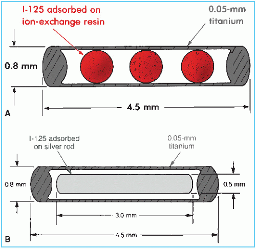 Figure 15.3. Schematic diagram of 125I seeds. A: Model 6702. B: Model 6711. (From Medical Products Division, 3M Co., New Brighton, MN, with permission.) |
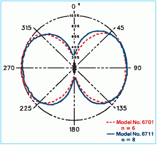 Figure 15.4. Angular photon fluence distribution from 125I seeds. The relative photon fluence in any direction is proportional to the radial distance from the seed to the plotted curve. n is the number of seeds used to obtain average results. (From Ling CC, Yorke ED, Spiro IS, et al. Physical dosimetry of 125I seeds of a new design for interstitial implant. Int J Radiat Oncol Biol Phys. 1983;9:1747, with permission.) |
G. PALLADIUM-103
103Pd seeds have relatively more recently become available for use in brachytherapy. Their clinical applications are similar to those of 125I. Having a shorter half-life (17 days) than that of 125I (59.4 days), 103Pd may provide a biologic advantage in permanent implants because the dose is delivered at a much faster rate (22).
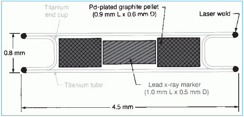 Figure 15.5. Schematic diagram of 103Pd seed (model 200). (From Theragenics Corp., Norcross, GA, with permission.) |
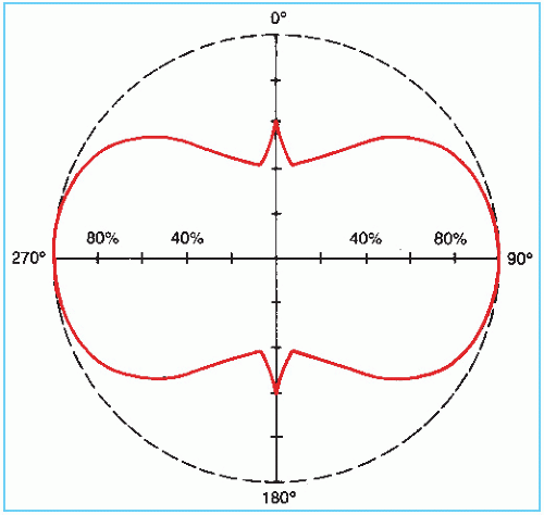 Figure 15.6. Photon fluence distribution in air for 103Pd seed. (From Meli JA, Anderson LL, Weaver KA. Dose distribution. In: Interstitial Collaborative Working Group, ed. Interstitial Brachytherapy. New York, NY: Raven; 1990:21, with permission.) |
The palladium-103 seed model 2003 consists of a laser-welded titanium tube containing two graphite pallets plated with 103Pd (Fig. 15.5). A lead marker between the pallets provides radiographic identification.
103Pd decays by electron capture with the emission of characteristic x-rays in the range of 20 to 23 keV (average energy 20.9 keV) and Auger electrons. The photon fluence distribution around the source is anisotropic due to the self-absorption by the source pallets, the welds, and the lead x-ray marker (Fig. 15.6). The dosimetry data for 103Pd are sparse. The reader is referred to Meigooni et al. (23) and Chiu-Tsao and Anderson (24) for dose-distribution data.
1The ICRU (2) defines the exposure rate constant as 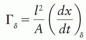 where (dx/dt)δ is the exposure rate due to photons of energy greater than δ, at a distance l from a point source of activity A. Special units of Γδ are R-m2/h/Ci or any convenient multiple of these. This quantity replaces, but is not identical to, the specific γ-ray constant. The latter applies to γ rays only and does not include the exposure rate of emitted x-rays such as characteristic x-rays and internal bremsstrahlung. The ICRU (3) has recommended that a quantity called air kerma rate constant be used instead of the exposure rate constant. This quantity is still named Γδ, but is now defined as
 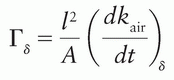 where kair is the air kerma. The SI unit for this quantity is m2-J/kg. When the special names gray (Gy) and becquerel (Bq) are used, the unit becomes m2-Gy/Bq/s.
where (dx/dt)δ is the exposure rate due to photons of energy greater than δ, at a distance l from a point source of activity A. Special units of Γδ are R-m2/h/Ci or any convenient multiple of these. This quantity replaces, but is not identical to, the specific γ-ray constant. The latter applies to γ rays only and does not include the exposure rate of emitted x-rays such as characteristic x-rays and internal bremsstrahlung. The ICRU (3) has recommended that a quantity called air kerma rate constant be used instead of the exposure rate constant. This quantity is still named Γδ, but is now defined as where kair is the air kerma. The SI unit for this quantity is m2-J/kg. When the special names gray (Gy) and becquerel (Bq) are used, the unit becomes m2-Gy/Bq/s.2Medical Products Division/3M, New Brighton, Minnesota.
3Manufactured by Theragenics Corp., Buford, Georgia.
15.2. CALIBRATION OF BRACHYTHERAPY SOURCES
A. SPECIFICATION OF SOURCE STRENGTH
Historically, the strength of a brachytherapy source has been specified in several ways.
A.1. Activity
The source strength for any radionuclide may be specified in terms of millicuries (mCi). The exposure rate at any particular point is proportional to the product of activity and its exposure rate constant. Errors, however, may be introduced in this method from the fact that corrections
must be applied for the source and wall filtration and that the exposure rate constant may not be known accurately. It should be recalled that the accuracy of the exposure rate constant depends critically on the accurate knowledge of the spectroscopic data and the relevant absorption coefficients.
must be applied for the source and wall filtration and that the exposure rate constant may not be known accurately. It should be recalled that the accuracy of the exposure rate constant depends critically on the accurate knowledge of the spectroscopic data and the relevant absorption coefficients.
A.2. Exposure Rate at a Specified Distance
The National Council on Radiation Protection and Measurements (NCRP) (25) recommends that the strength of any γ emitter should be specified directly in terms of exposure rate in air at a specified distance such as 1 m. This specification can be carried out simply by measuring exposure rate in free air at a distance sufficiently large that the given source can be treated as a point. Long distance measurement geometry minimizes the dependence of the calibration upon the construction of the source and the detector because both can be treated as points. In addition, the effect of oblique transmission of photons through the source capsule becomes negligible. Loevinger (26) has recommended calibration of brachytherapy sources in terms of absorbed dose in water, close to the source.
A.3. Equivalent Mass of Radium
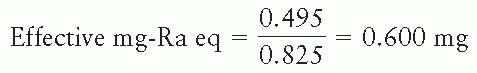
There are historical reasons that make it convenient to specify brachytherapy sources in terms of the equivalent mass of radium. Because some users, especially the physicians who are accustomed to radium sources, continue to use mg-Ra eq, it has been suggested (25) that the exposure rate could be expressed in terms of “effective” equivalent mass of radium. This conversion is simply made by dividing the exposure rate at 1 m by the exposure rate constant of radium (point source filtered by 0.5 mm Pt) at 1 m. It should, however, be emphasized that the best way to calibrate and specify brachytherapy sources is still in terms of exposure rate or air kerma rate at a distance of 1 m. The effective mg-Ra eq should be used only to provide output comparison with radium sources.
EXAMPLE
An iridium-192 source has been calibrated and its strength is specified as 0.495 mR/h at 1 m. What is the strength of this source in terms of effective mg-Ra eq?
Exposure rate constant of radium filtered by 0.5 mm Pt = 8.25 R-cm2/h-mg = 0.825 mR-m2/h-mg.
Note that such a conversion of units must explicitly specify the radium source in terms of a point source and its filtration.
A.4. Apparent Activity
If the source is calibrated in terms of exposure rate at 1 m, its strength may be specified as apparent activity. It is defined as the activity of a bare point source of the same nuclide that produces the same exposure rate at 1 m as the source to be specified. The apparent activity of a brachytherapy source is determined by dividing the measured exposure rate at 1 m with the exposure rate constant of the unfiltered source at 1 m.
Vendors of brachytherapy sources may specify source strength as apparent activity, although the original calibration is done in terms of exposure rate. In order for the user to calculate exposure rate from the apparent activity, the exposure rate constant to be used must be the same as the one used by the vendor. Thus, the exposure rate constant is used as a dummy constant in this conversion; that is, a purely arbitrary value would do, provided its product with the apparent activity yields the same exposure rate as determined by the original calibration.
A.5. Air Kerma Strength
Although exposure rate at a specified distance is appropriate in designating source strength, the quantity exposure is being phased out. Most of the standards laboratories have already replaced exposure by the quantity air kerma. In keeping with these trends, the American Association of Physicists in Medicine (AAPM) recommended the quantity air kerma strength for the specification of brachytherapy sources.
The air kerma strength is defined (27) as the product of air kerma rate in “free space” and the square of the distance of the calibration point from the source center along the perpendicular bisector; that is
where SK is the air kerma strength and  is the air kerma rate at a specified distance l (usually 1 m). Recommended units for air kerma strength are µGy-m2/h.
is the air kerma rate at a specified distance l (usually 1 m). Recommended units for air kerma strength are µGy-m2/h.Because no single system is being currently followed universally, it is instructive to derive relationships between the different quantities being used for source strength specification.
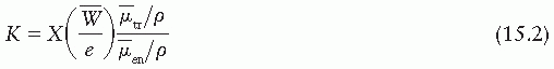
where K is kerma, X is exposure,  is the average energy absorbed per unit charge of ionization in air, and
  and
and  are, respectively, the average values of the mass transfer coefficient and the mass energy absorption coefficient of air for the photons. Also,
is the average energy absorbed per unit charge of ionization in air, and and are, respectively, the average values of the mass transfer coefficient and the mass energy absorption coefficient of air for the photons. Also,where  is the average energy of an electron lost to bremsstrahlung. However, in the energy range of brachytherapy photons and for the air medium,
  . Therefore,
is the average energy of an electron lost to bremsstrahlung. However, in the energy range of brachytherapy photons and for the air medium, . Therefore,
From Equations 15.1 and 15.4,
Thus, the exposure calibration of a brachytherapy source can be readily converted to air kerma strength by the use of Equation 15.5. If exposure rate is measured in R/h at l = 1 m,
SK =  (R/h) (0.876 cGy/R) (1 m)2
(R/h) (0.876 cGy/R) (1 m)2where 0.876 cGy/R is the value of  for dry air (see Section 8.3) or
for dry air (see Section 8.3) orMILLIGRAM RADIUM EQUIVALENT. By definition, 1 mg-Ra eq gives 8.25 × 10⁻⁴ R/h at 1 m; therefore, in terms of air kerma strength (from Equation 15.6):
or
APPARENT ACTIVITY. By definition, 1 unit of apparent activity, App, gives exposure rate at 1 m equal to the exposure rate constant of the specified source at 1 m. Using the exposure rate constants given in Table 15.1 and Equation 15.6, 1 µGy-m2/h = 0.348 mCi for 137Cs; 0.243 mCi for 192Ir; 0.486 mCi for 198Au; 0.787 for 125I; and 0.773 for 103Pd. These apparent activities per unit air kerma strength may be used to convert source strengths calibrated in air kerma strengths to apparent activities in millicuries.
EXAMPLE
An 192Ir seed calibrated by an accredited dose calibration laboratory (ADCL) has air kerma strength of 5.00 µGy-m2/h. What is the strength of the source (a) in units of mg-Ra eq and (b) in units of mCi (apparent activity)?
Using the conversion factors derived above,
(a) equivalent mass of radium = 5.00 × 0.138
= 0.69 mg-Ra eq
(b) apparent activity = 5.00 × 0.243
= 1.22 mCi
B. EXPOSURE RATE CALIBRATION
The National Institute of Standards and Technology (NIST) has established exposure rate calibration standards for some of the brachytherapy sources (e.g., 226Ra, 60Co, 137Cs, and 192Ir). The NIST method consists of calibrating a working standard of each type using open-air geometry
and a series of spherical graphite cavity chambers (28,29). A given source is then calibrated by intercomparison with the working standard using a 2.5-L spherical aluminum ionization chamber, positioned at a distance of about 1m. A similar procedure is used for calibrating a radium source except that the working standards of radium have been calibrated in terms of actual mass of radium.
and a series of spherical graphite cavity chambers (28,29). A given source is then calibrated by intercomparison with the working standard using a 2.5-L spherical aluminum ionization chamber, positioned at a distance of about 1m. A similar procedure is used for calibrating a radium source except that the working standards of radium have been calibrated in terms of actual mass of radium.
Because of their lower exposure rate and shorter half-life, 192Ir is calibrated in a slightly different manner (29). A composite source containing about 50 seeds is calibrated in terms of exposure rate at 1 m in open-air scatter-free geometry, as in the case of 137Cs sources, using spherical graphite chambers. Each seed is then measured individually in a well-type ionization chamber to calibrate the chamber. This well-type ionization chamber now serves as the working standard for calibrating 192Ir seeds.
125I seeds are calibrated at the NIST in terms of exposure rate in free space at 1 m using a free-air ionization chamber (30). For routine calibrations a well-type ionization chamber is used whose calibration is maintained by a free-air chamber as the primary standard.
Calibration of clinical sources should be directly traceable to NIST or one of the AAPM ADCLs. This means that the sources should be calibrated by direct comparison with a NIST- or ADCL-calibrated source of the same kind (i.e., the same radionuclide with the same encapsulation, size, and shape). If a well-type ionization chamber is used, it should bear a calibration factor determined with a NIST- or ADCL-calibrated source of the same kind.
B.1. Open-Air Measurements
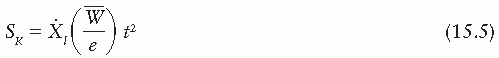
Figure 15.7 is a schematic representation of an open-air measurement geometry for the calibration of brachytherapy sources. The arrangement consists of a large source to ion chamber distance relative to source and detector dimensions. The apparatus is set up as far away as possible from potential scattering surfaces. Because the output from brachytherapy sources is low at large distances, the chamber volume should be large, for example, 100 mL or larger. A signal-to-noise ratio greater than 100:1 should be achievable.
Because of the difficulty in obtaining “good geometry” conditions, the open-air method is a time-consuming measurement. It is not suitable for routine calibration checks required in a busy department. A well-type ionization chamber is more suited to routine measurements.
B.2. Well-Type Ion Chambers
Routine calibration of brachytherapy sources is usually carried out with a “re-entrant”-type ion chamber in which the walls of the chamber surround the source, approximating a 4π measurement geometry. Examples of such chambers are those designed by the British National Physics Laboratory (31), a re-entrant chamber designed by Radiological Physics Center (32), a spherical aluminum chamber designed by NIST (33), and commercially available dose calibrators (34, 35, 36)
Figure 15.8 is a schematic drawing of a dose calibrator, Capintec Model CRC-10. This unit consists of an aluminum wall ion chamber filled with argon gas under high pressure. The collection potential applied to the chamber is about 150 V. A source holder is devised to reproduce the source geometry in relation to the surrounding chamber walls.
The dose calibrator is traditionally used for assay of radiopharmaceuticals in which the instrument response is interpreted as activity in units of millicuries. These activity calibrations of various isotopes are based on relative chamber response measured by intercomparison with the respective standards calibrated by NIST directly in terms of activity (37). However, these standards are usually in the form of an aqueous suspension of the isotope sealed in a
glass ampule. These vendor calibrations of the instrument are, therefore, not valid for brachytherapy sources because of differences in construction between brachytherapy and standard sources. Even the practice of using a radium standard for calibrating different sources is prone to significant errors due to energy dependence of the instrument (35,36,38). In addition, the response of well chambers is known to depend on the source position in the well and on the length of the source (32). Correction factors must be determined for these effects for a given instrument and the type of sources to be calibrated.
glass ampule. These vendor calibrations of the instrument are, therefore, not valid for brachytherapy sources because of differences in construction between brachytherapy and standard sources. Even the practice of using a radium standard for calibrating different sources is prone to significant errors due to energy dependence of the instrument (35,36,38). In addition, the response of well chambers is known to depend on the source position in the well and on the length of the source (32). Correction factors must be determined for these effects for a given instrument and the type of sources to be calibrated.
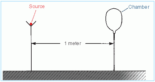 Figure 15.7. Schematic drawing of open-air geometry for exposure rate calibration of brachytherapy sources. |
 Figure 15.8. Schematic drawing of a dose calibrator, Capintec Model CRC-10. (From Williamson JF, Khan FM, Sharma SC, et al. Methods for routine calibration of brachytherapy sources. Radiology. 1982; 142:511, with permission.) |
The energy dependence of the chamber arises from absorption and scattering of photons and secondary electrons in the chamber walls and the gas. Besides this intrinsic energy dependence, oblique filtration through the source encapsulation affects the chamber response both by photon absorption and by producing changes in the energy spectrum. This effect of source construction on the chamber response has been studied in detail by Williamson et al. (34,39) for commonly used brachytherapy sources. These authors conclude: “In these apparatuses, all one can count on is a linear response with respect to exposure rate given fixed energy, filtration, and source position. For each isotope, an exposure calibrated standard is needed” (34). These studies support the recommendations that the brachytherapy sources should be calibrated in terms of exposure rate using exposure calibrated standards of the same kind (25,26).
15.3. CALCULATION OF DOSE DISTRIBUTIONS
A. EXPOSURE RATE
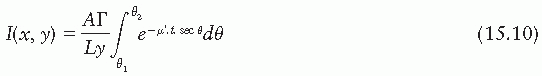
Exposure rate distribution around a linear brachytherapy source can be calculated using the Sievert integral, introduced by Sievert (40) in 1921. The method (1,41) consists of dividing the line source into small elementary sources and applying inverse square law and filtration corrections to each. Consider a source of active length L and filtration t (Fig. 15.9). The exposure rate dI at a point P(x, y) contributed by the source element of length dx is given by
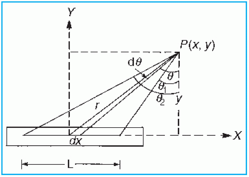 Figure 15.9. Diagram illustrating geometric relationships used in calculation of exposure at point P, from a linear source. |
where A and γ are the activity and exposure rate constant of the unfiltered source and µ′ is the effective attenuation coefficient for the filter. Other variables are defined by Figure 15.9. Making use of the following relationships:
r = y sec θ
x = y tan θ
dx = y sec2 θdθ
The above Sievert integral can be evaluated by numerical methods (1).
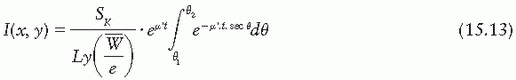
If the source intensity is specified in terms of exposure rate  s at a specified distance s far from the source (i.e., s » L), then the Sievert integral can be written as
s at a specified distance s far from the source (i.e., s » L), then the Sievert integral can be written as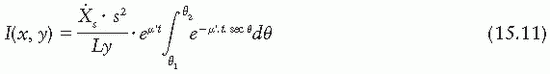
Alternatively, if the source strength is specified in terms of equivalent mass of radium, meq, such that  s = meq.ΓRas-2 then
s = meq.ΓRas-2 then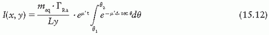
If the source strength is specified in air kerma strength, then
Several additional corrections are applied to compute the exposure rate accurately using the Sievert integral. A correction for self-absorption in the source material, although small for clinical sources, has been used by Shalek and Stovall (1). Wall thickness, t, should be corrected for the internal radius of the source, because some photons traverse a thickness of filter greater than the radial thickness of the wall (42,43). Depending on the type of source and filtration, the energy spectrum may be significantly altered by the filter. Not only is an “effective attenuation coefficient” needed, but also this coefficient varies with filter thickness (43,44). This problem becomes more severe when the effects of oblique filtration are considered (45).
In the case of 226Ra encapsulated in platinum, measured values of µ′ (43,44) may be used (Fig. 15.10). However, if such data are not available for a given source-filter combination, calculated values have to be used. Williamson et al. (45) give the following expression for µ′ as a function of filter thickness d:
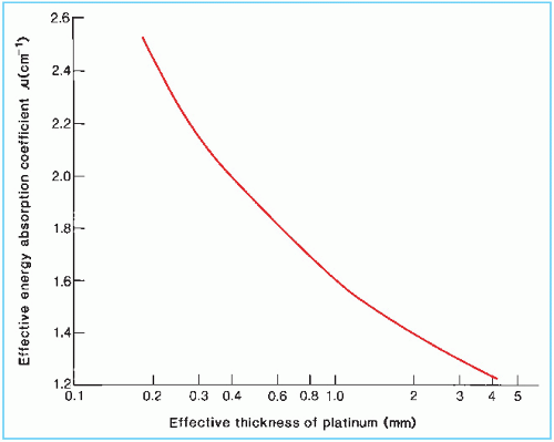 Figure 15.10. Effective energy absorption coefficients of radium γ rays in platinum. (Data are from Whyte GN. Attenuation of radium gamma radiation in cylindrical geometry. Br J Radiol. 1955;28:635; and Keyser GM. Absorption correction for radium standardization. Can J Phys. 1951;29:301.) |
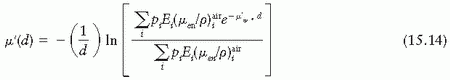
where pi denotes the number of photons with energy Ei emitted per disintegration, and  is the mass energy absorption coefficient in air for photon of energy Ei.
is the mass energy absorption coefficient in air for photon of energy Ei.Because the Sievert integral uses the energy absorption coefficient, the underlying assumption is that the emitted energy fluence is exponentially attenuated by the filter thickness traversed by the photons. This is an approximation that has been shown to work well for 226Ra and 192Ir seeds in the region bounded by the active source ends (1,45). However, Monte Carlo simulations (45) have shown that beyond the end of the active source region, the Sievert approach introduces significant errors and practically breaks down in the extreme oblique directions.
Related posts:


Stay updated, free articles. Join our Telegram channel

Full access? Get Clinical Tree


