Treatment Planning III: Field Shaping, Skin Dose, and Field Separation
Shielding of vital organs within a radiation field is one of the major concerns of radiation therapy. Considerable time and effort are spent in shaping fields not only to protect critical organs, but also to avoid unnecessary irradiation of the surrounding normal tissue. Attendant to this problem is the effect on skin dose and the buildup of dose in the subcutaneous tissue when shielding blocks mounted on a plastic tray are inserted into the beam. Skin sparing is an important property of megavoltage photon beams, and every effort should be directed to maintaining this effect when irradiating normal skin.
Another problem frequently encountered in radiation therapy is the matching of adjacent fields. This situation arises when radiation fields available with the equipment are not large enough to encompass the entire target volume. In some cases, the target volume is divided into two parts, so treatment to the second part does not commence until the treatment course to the first part has been completed. Such a scheme is designed to avoid toxicity due to irradiating an excessive volume of tissue. Multiple adjacent fields are also used when tumor distribution or patient anatomy does not allow coplanar fields (fields with central axes in the same plane). The main problem with these techniques is the possibility of extreme dose inhomogeneity in the junctional region. Because radiation beams are divergent, adjacent fields can overlap at depth and give rise to regions of excessive dose or hot spots. Overlaps can be avoided by separating the fields, but this in turn can give rise to areas of reduced dose or “cold spots.”
This chapter on treatment planning focuses on the above problems and discusses their possible solutions.
13.1. FIELD BLOCKS
The shaping of treatment fields is primarily dictated by tumor distribution—local extensions as well as regional metastases. Not only should the dose to vital organs not exceed their tolerance, but also the dose to normal tissue, in general, should be minimized. As long as the target volume includes, with adequate margins, the demonstrated tumor as well as its presumed occult spread, significant irradiation of the normal tissue outside this volume must be avoided as much as possible. These restrictions can give rise to complex field shapes, which require intricate blocking.
The frequency and complexity of field shaping vary from institution to institution. However, if complex techniques involving elaborate blocking are used often, it is necessary to establish a rational system of field shaping.
A. BLOCK THICKNESS
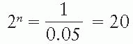
Shielding blocks are most commonly made of lead. The thickness of lead required to provide adequate protection of the shielded areas depends on the beam quality and the allowed transmission through the block. A primary beam transmission of 5% through the block is considered acceptable for most clinical situations. If n is the number of half-value layers to achieve this transmission:
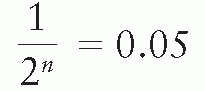
TABLE 13.1 Recommended Minimum Thickness of Lead for Shieldinga | ||||||||||||||||||||||||||||||
|---|---|---|---|---|---|---|---|---|---|---|---|---|---|---|---|---|---|---|---|---|---|---|---|---|---|---|---|---|---|---|
| ||||||||||||||||||||||||||||||
or
or
n log 2 = log 20
or
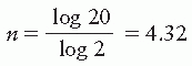
Thus, a thickness of lead greater than 4.3 half-value layers would give less than 5% primary beam transmission and is, therefore, recommended for most clinical shielding.
Shielding against primary radiation for superficial and orthovoltage beams is readily accomplished by thin sheets of lead that can be placed or molded on to the skin surface. However, as the beam energy increases to the megavoltage range, the thickness of lead required for shielding increases substantially. The lead blocks are then placed above the patient supported in the beam on a transparent plastic tray, called the shadow tray. Table 13.1 gives the recommended lead shield thicknesses for various-quality beams.
Although the primary beam transmission can be reduced further by using extra thick blocks, the reduction in dose in the shielded region may not be that significant due to the predominance of scattered radiation from the adjoining open areas of the field.
B. BLOCK DIVERGENCE
Ideally, the blocks should be shaped or tapered so that their sides follow the geometric divergence of the beam. This minimizes the block transmission penumbra (partial transmission of the beam at the edges of the block). However, divergent blocks offer little advantage for beams with large geometric penumbra. For example, in the case of 60Co, the sharpness of the beam cutoff at the block edge is not significantly improved by using divergent blocks. Also, for some clinical situations such as making last minute alterations in the field blocking, this sharpness is not critical or worth the time required for making divergent blocks, which have to be invariably custom designed for a given treatment setup. Therefore, most institutions keep a stock of straight-cut blocks of various shapes and dimensions. Divergent blocks are most suited for beams having small focal spots such as with linac beams. Because the sides of these blocks follow beam divergence, one can reduce the lateral dimensions by designing the shields for smaller source to block distances without increasing the block transmission penumbra.
13.2. FIELD SHAPING
A. CUSTOM BLOCKING
Although a number of systems have been used for field shaping (1, 2, 3, 4, 5, 6, 7, 8), the one introduced by Powers et al. (1) is most commonly used in radiation therapy. This system uses a low melting point alloy, Lipowitz metal (brand name, Cerrobend), which has a density of 9.4 g/cm3 at 20°C (˜83% of lead density). This material consists of 50.0% bismuth, 26.7% lead, 13.3% tin, and 10.0% cadmium (1). (Cadmium-free Cerrobend is also available.) The main advantage of Cerrobend over lead is that it melts at about 70°C (Cadmium-free at 95°C) (compared with 327°C for lead) and, therefore, can be easily cast into any shape. At room temperature, it is harder than lead.
The minimum thickness of Cerrobend blocks required for blocking may be calculated from Table 13.1 using its density ratio relative to lead (e.g., multiply lead thickness by 1.21). In the megavoltage range of photon beams, the most commonly used thickness is 7.5 cm, which is equivalent to about 6 cm of pure lead. The manual procedure for constructing Cerrobend blocks starts with a simulator radiograph, port film or a digitally reconstructed radiograph (DRR) on which the outline of the treatment field indicating areas to be shielded is drawn. The film is then used to construct divergent cavities in a Styrofoam block that are used to cast Cerrobend blocks. Figure 13.1 shows a Styrofoam-cutting device that consists of an electrically heated wire that pivots about a point simulating the source or the x-ray target. The film, the Styrofoam block, and the wire apparatus are so adjusted that the actual treatment geometry (same source to film and source to block distances) is obtained. The lower end of the wire traces the outline on the film. There are also automated systems which can cut a Styrofoam block based on a block outline sent electronically from the treatment planning system. If “positive” blocks such as lung blocks are to be made, cavities are cut in the Styrofoam with the heated segment of the wire and subsequently filled with melted Cerrobend. If a “negative” block with central area open and peripheral areas blocked is desired, an inner cut is first made to outline the field opening. An outer rectangular cut is then made to define the collimator field with a 1- to 2-cm margin. The three Styrofoam pieces thus made are placed on a Lucite plate and carefully aligned relative to the central axis. The intermediate piece, corresponding to the areas to be shielded, is then removed and Cerrobend is poured into the cavity.
It is important that the Cerrobend is poured slowly to prevent formation of air bubbles. Also, the Styrofoam block should be pressed tightly against a rubber pad at the bottom to avoid leakage of the liquid metal. The inside walls of the cavity may be sprayed with silicone for easy release of the Styrofoam pieces from the block.
The blocks can be mounted on a Lucite plate or blocking tray, which is premarked with the central axis cross-hairs. Blocks can also be placed on a template made on a clear film by tracing the outline of the field at the shadow tray position, while the port film outline is placed at the distance at which the radiograph was taken.
Figure 13.2 shows examples of Cerrobend blocks, one constructed for shielding lungs and the other for a head and neck field.
B. INDEPENDENT JAWS
Asymmetric fields are sometimes used to block off a part of the field without changing the position of the isocenter. Although blocking is often used to generate irregular field shapes, rectangular blocking can be easily done by independently movable collimators, or jaws. This feature
is very convenient when matching fields or beam splitting. In the latter case, the beam is blocked off at the central axis to remove divergence. Whereas half-beam blocks have been used as beam splitters in the past, this can now be done simply by moving in the independent jaws.
is very convenient when matching fields or beam splitting. In the latter case, the beam is blocked off at the central axis to remove divergence. Whereas half-beam blocks have been used as beam splitters in the past, this can now be done simply by moving in the independent jaws.
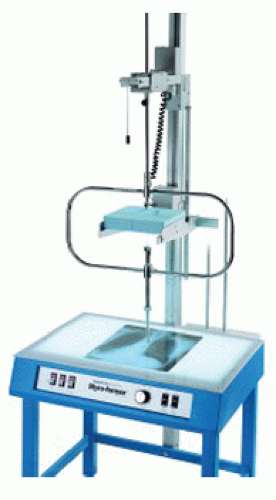 Figure 13.1. Photograph of block cutter. (Courtesy of Huestis Machine Corp., Bristol, RI.) [Source: www.huestis.com.] |
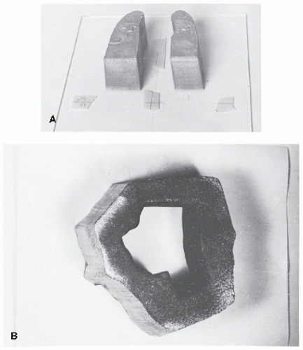 Figure 13.2. A: Cerrobend blocks for lung shielding. B: Custom blocks for head and neck. |
Most modern machines are equipped with independently movable jaws. Operationally, the independent jaw option is interlocked to avoid errors in the setting of symmetric fields, in which case the opposite jaws open or close symmetrically. One of the effects of asymmetric collimation is the change in the physical penumbra (defined in Section 4.7A.3) and the tilt of the isodose curves toward the blocked edge (Fig. 13.3). This effect is simply the result of blocking, which eliminates photon and electron scatter from the blocked portion of the field, thereby reducing the dose near the edge. The same effect would occur on the isodose curves if the blocking were done with a lead or Cerrobend block on a tray.
When asymmetric fields are used, special considerations must be given to the beam flatness and the dosimetric parameters used to calculate monitor units. Khan et al. (9) have proposed a system of dose calculation for fields generated by asymmetric collimators, which was discussed in Chapter 10.
C. MULTILEAF COLLIMATORS
A multileaf collimator (MLC) for photon beams consists of a large number of collimating blocks or leaves that can be driven automatically, independent of each other, to generate a field of any shape (Fig. 13.4). Typical MLC systems consist of 60 to 80 pairs, independently driven. The individual leaf has a width of 1 cm or less as projected at the isocenter. The leaves are made of tungsten alloy (ρ = 17.0 to 18.5 g/cm3) and have thickness along the beam direction ranging from 6 cm to 7.5 cm, depending on the type of accelerator. The leaf thickness is sufficient to provide primary x-ray transmission through the leaves of less than 2% (compared with about 1% for jaws and 3.5% for Cerrobend blocks). The interleaf (between sides) transmission is usually less than 3%. The primary beam transmission may be further minimized by combining jaws with the MLC in shielding areas outside the MLC field opening.
Some MLC systems have double-focused leaves; that is, the leaves form a cone of irregular cross section diverging from the source position and move on a spherical shell centered at the source. The rationale behind a double-focused MLC is to provide a sharp beam cutoff at the edge. However, for high-energy beams this objective is achieved only to a limited extent, because the dose falloff at the edge is largely determined by laterally scattered photons and electrons. Because double-focused MLCs are difficult to manufacture, some systems have been designed with rounded leaf edges and directions of travel perpendicular to the central ray. The purpose of rounded edges is to provide constant beam transmission through a leaf edge, regardless of its position in the field.
 Figure 13.3. Comparison of isodose distribution with half the beam blocked by an independent jaw versus a block on a tray. Notice close agreement as well as the tilt of the isodose curves toward the blocked edge. |
An important consideration in the use of MLCs for stationary fields is the conformity between the planned field boundary, which is continuous, and the jagged stepwise boundary created by the MLC. The degree of conformity between the two depends not only on the projected leaf width, but also on the shape of the target volume and the angle of rotation of the collimator. Optimization of MLC rotation and setting has been discussed by Brahme (10). His analysis shows that the best orientation of the collimator is when the direction of motion of the leaves is parallel with the direction in which the target volume has the smallest cross section.
The physical penumbra (section 11.1) with MLC is larger than that produced by the collimator jaws or the Cerrobend blocks (Fig. 13.5). This is usually not a serious drawback except for
the treatment of small fields or when blocking is required close to critical structures. Also, jaggedness of the field edges makes it difficult to match adjacent fields.
the treatment of small fields or when blocking is required close to critical structures. Also, jaggedness of the field edges makes it difficult to match adjacent fields.
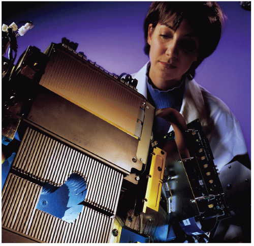 Figure 13.4. Varian Millennium multileaf collimator. (Courtesy of Varian Associates, Palo Alto, CA.) [Source: www. varian.com.] |
The use of MLC in blocking and field shaping is ideally suited for treatments requiring large numbers of multiple fields because of automation of the procedure, thus resulting in a significant reduction of setup time. MLC can practically eliminate the use of Cerrobend blocking except for shaping small fields or “island” blocking in which an area within the open portion of the fields needs to be blocked.
The importance of MLC is not just the replacement of Cerrobend blocking. The greater impact of this technology is in the automation of field shaping and modulation of beam intensity. Modern radiotherapy techniques such as 3-D conformal radiation therapy (Chapter 19) and intensity-modulated radiation therapy (Chapter 20) are dependent on dynamically controlled MLCs. Other applications include dynamic wedges and electronic compensation. For further details on MLC designs and applications, the reader is referred to a review by Boyer (11).
13.3. SKIN DOSE
When a patient is treated with a megavoltage beam, the surface dose or skin dose can be substantially lower than the maximum dose that occurs in the subcutaneous tissues. In contrast to lower-energy beams (e.g., superficial and orthovoltage x-rays), which give rise to maximum ionization at or close to the skin surface, the megavoltage beams produce an initial electronic buildup with depth. Consequently, the surface dose is less than the maximum dose that occurs at a depth downstream. The higher the energy, the deeper is the depth of maximum dose.
Skin sparing is one of the most desirable features of high-energy photon beams. However, this effect may be reduced or even lost if the beam is excessively contaminated with secondary electrons. In the following sections, the sources of this contamination and the methods used to reduce it will be discussed.
A. ELECTRON CONTAMINATION OF PHOTON BEAMS
Surface dose is the result of electron contamination of the incident beam as well as the backscattered radiation (both electrons and photons) from the medium. It is well known that all x-ray
and γ-ray beams used in radiation therapy are contaminated with secondary electrons. These electrons are mostly Compton electrons produced by photon interactions with the collimator, the flattening filter, and other materials in the path of the beam such as wedges and shadow tray. If a shadow tray is the last absorber in the beam, it will absorb most of the electrons incident on it but, in turn, will generate its own Compton electrons. The tray is then the main contributor of contaminant electrons incident on the patient.
and γ-ray beams used in radiation therapy are contaminated with secondary electrons. These electrons are mostly Compton electrons produced by photon interactions with the collimator, the flattening filter, and other materials in the path of the beam such as wedges and shadow tray. If a shadow tray is the last absorber in the beam, it will absorb most of the electrons incident on it but, in turn, will generate its own Compton electrons. The tray is then the main contributor of contaminant electrons incident on the patient.
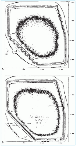 Figure 13.5. Comparison of physical penumbra associated with multileaf collimator A: and Cerrobend blocks B: Field size = 15 × 15, depth = 10 cm, and energy = 6 MV. Dose distribution normalized to 100% at central axis. (From Galvin JM, Smith AR, Moeller RD, et al. Evaluation of multileaf collimator design for a photon beam. Int J Radiat Oncol Biol Phys. 1992;23:789-801, with permission.) |
Electron contamination also effects the variation of dose in the buildup region with field size. It is well known that as the field size increases, the depth dose in the buildup region increases, resulting in a shift in the depth of maximum dose, dmax, to increasingly shallower depths (12, 13, 14). Several investigators (15, 16, 17) have shown that this effect is predominantly caused by the secondary electrons.
B. MEASUREMENT OF DOSE DISTRIBUTION IN THE BUILDUP REGION
Because of the steep dose gradient in the buildup region, the size of the dosimeter along the beam direction should be as small as possible. Extrapolation chambers (see Chapter 6) are
the instruments of choice for these measurements. However, only few institutions have these instruments available. Instead, fixed-separation plane-parallel ionization chambers are most commonly used for this purpose. Although these chambers are very suitable for measurements in regions of severe dose gradients, their response is dependent, in a complex manner, on their design. Several papers have discussed the inaccuracies in the measurement of dose in the buildup region when using fixed-separation plane-parallel chambers. These inaccuracies arise primarily as a result of electron scattering from the side walls of the chamber (18, 19, 20). These may be minimized by using a smaller plate separation and wider guard ring in the design of the chamber. Furthermore, the chambers may exhibit a significant polarity effect in the buildup region, which may be corrected by averaging the readings obtained with the positive and negative polarities. Gerbi and Khan (21) have studied several commercially available plane-parallel chambers and found that they overrespond in the buildup region. The errors were more severe at the surface and for the lower beam energies (e.g., 60Co). The magnitude of overresponse at the surface for a 60Co beam ranged from 9% to 20% for the chambers studied.
the instruments of choice for these measurements. However, only few institutions have these instruments available. Instead, fixed-separation plane-parallel ionization chambers are most commonly used for this purpose. Although these chambers are very suitable for measurements in regions of severe dose gradients, their response is dependent, in a complex manner, on their design. Several papers have discussed the inaccuracies in the measurement of dose in the buildup region when using fixed-separation plane-parallel chambers. These inaccuracies arise primarily as a result of electron scattering from the side walls of the chamber (18, 19, 20). These may be minimized by using a smaller plate separation and wider guard ring in the design of the chamber. Furthermore, the chambers may exhibit a significant polarity effect in the buildup region, which may be corrected by averaging the readings obtained with the positive and negative polarities. Gerbi and Khan (21) have studied several commercially available plane-parallel chambers and found that they overrespond in the buildup region. The errors were more severe at the surface and for the lower beam energies (e.g., 60Co). The magnitude of overresponse at the surface for a 60Co beam ranged from 9% to 20% for the chambers studied.
Thin layers (<0.5 mm) of thermoluminescent dosimeter (TLD) material can also be used for measuring dose distribution in the buildup region. The TLD phosphor (e.g., LiF) can be in the form of chips, crystals embedded in plastic, or powder layers (18,22,23). The surface dose may be obtained by extrapolating the depth-dose distribution curve to zero depth. In vivo measurements of surface dose can also be made by placing thin TLD chips directly on the skin surface. Such measurements are useful in checking dosimetry if an unacceptable degree of skin reaction develops.
C. SKIN SPARING AS A FUNCTION OF PHOTON ENERGY
Studies have shown that the dose distribution in the buildup region depends on many variables such as beam energy, source to surface distance (SSD), field size, and position of secondary blocking tray (18,22, 23, 24, 25, 26). Table 13.2 gives values for different energies. These data are presented here as an example and should not be considered universal for all machines, especially for depths less than 2 mm. Reasonable agreement between different machines has been shown to exist for greater depths.
Examination of Table 13.2 would also indicate that for all energies the dose increases rapidly within the first few millimeters and then gradually achieves its maximum value at the depth of peak dose. For example, in the case of 4 MV, the percent depth dose increases from 14% to 74% in the first 2 mm, reaches 94% at a 5-mm depth, and achieves its maximum value at a 10-mm depth. A practical application of this phenomenon is the case in which buildup bolus (Chapter 12) is used intentionally to maximize the dose on the skin (e.g., covering a scar with a strip of bolus). A tissue-equivalent bolus of 5 to 6 mm of thickness is usually adequate for 4 MV. Thus,
the thickness of bolus required to achieve 90% to 95% buildup of dose is substantially less than the depth of maximum dose.
the thickness of bolus required to achieve 90% to 95% buildup of dose is substantially less than the depth of maximum dose.
TABLE 13.2 Buildup Dose Distribution in Polystyrene for a 10 × 10-cm Field | ||||||||||||||||||||||||||||||||||
|---|---|---|---|---|---|---|---|---|---|---|---|---|---|---|---|---|---|---|---|---|---|---|---|---|---|---|---|---|---|---|---|---|---|---|
|