Circulatory failure is associated with high mortality and morbidity. Advanced mechanical circulatory support devices (MCSDs) provide important treatment strategies designed to save patients’ lives. Multimodality imaging plays important roles in (1) assessing the need for MCSD placement; (2) identifying contraindications for MCSD; (3) guiding and confirming correct placement; (4) monitoring cardiac unloading/decompression and device function during circulatory support; (5) evaluating device complications; (6) assessing myocardial recovery; and (7) assisting device explantation. Imaging modalities employed for these purposes include transthoracic echocardiography (TTE), transesophageal echocardiography (TEE), computed tomography (CT), cardiac magnetic resonance (CMR) and positron emission tomography (PET), which may be used in different stages and clinical scenarios before or following MCSD implantation.
Clinical Overview
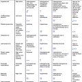
MCSDs are classified as temporary or durable mechanical support devices ( Table 14.1 ). Temporary MCSDs are used for directly or indirectly supporting left-sided, right-sided, biventricular, or cardio-respiratory failure. Temporary devices are often placed percutaneously, which requires either guidance with radiography (fluoroscopy) or echocardiography or both. Durable MCSDs may be used as a bridge for heart transplantation or as a destination therapy. Durable circulatory support may be used for years. A close collaboration between the heart failure/transplant team and imaging specialists is essential for achieving favorable outcomes.
| Temporary Devices | Durable Devices |
|---|---|
|
|
Diagnostic Strategies and Therapeutic Implications
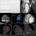
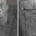
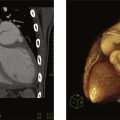
The intra-aortic balloon pump (IABP) is a flexible double-lumen catheter with a balloon mounted at the end. IABP is commonly placed percutaneously through the femoral artery or the left axillary artery. The tip of the IABP should be placed 1–2 cm below the origin of the left subclavian artery. Fluoroscopy is often used for guiding IABP placement. However, intra-operative placement of IABP during cardiac surgery can also be guided by TEE. Before IABP placement, contraindications to IABP should be excluded. Moderate or severe aortic valve insufficiency is considered a contraindication because counter-pulsation may increase aortic regurgitation. Significant atherosclerosis of the descending aorta and aortic arch, especially mobile atheroma should also be considered a relative contraindication since repeated balloon inflation may lead to dislodgement of the atheroma causing possible peripheral embolization or stroke ( Fig. 14.1 ). Descending aorta aneurysms and dissection are considered a contraindication. The balloon itself typically appears as an echo-dense image when deflated and a scattered echo density when inflated. There is no balloon-appeared image.

Impella is a continuous, axial flow device that aspirates blood from the left ventricle (LV) and then pumps blood into the ascending aorta. The device unloads LV volume and reduces end-diastolic pressure and LV wall stress leading to a reduction of oxygen consumption and increased cardiac output. An Impella device can be inserted using femoral, axillary, or transcaval access. Both TTE and TEE can be used for guiding placement. Preimplantation imaging assessment includes (1) evaluation of aortic pathology (ascending aortic dissection, severe aortic regurgitation, or presence of mechanical aortic valve prostheses) which constitute absolute contraindications; (2) detection of LV thrombi or ventricular septal defect. Fluoroscopy can be used to guide the placement of the device in the cardiac catheterization laboratory. The inflow catheter is radioopaque and appears as a teardrop on echocardiography and it should be placed about 3.5 cm from the aortic annulus for the Impella CP (with a nonechogenic pigtail), which is often inserted percutaneously, and about 5.0 cm from the aortic annulus for Impella 5.5 (without a pigtail), which is inserted surgically. The outflow should be positioned in the ascending aorta above the aortic valve (approximately 1.5 cm above the sinuses of Valsalva), which may be visualized on the parasternal long-axis view by two-dimensional echocardiography with color Doppler showing mosaic color flow. The tip of Impella should point at the LV apex and be away from the anterior leaflet of the mitral valve and the interventricular septum and also avoid tangling chords or papillary muscle ( Fig. 14.2 ). A device migration and malposition may lead to severe mitral regurgitation, if the device impinges on the mitral subvalvular apparatus. Inadequate systemic support may occur if the device is positioned too deep touching on LV wall to obstruct the inflow port or the outflow port is at or below the aortic valve. Mitral valve leaflet perforation and chordae tendineae rupture have been reported as complications. Other complications include ventricular arrhythmias, if the inflow catheter/device abuts an LV wall; hemolysis if there is a catheter obstruction (avoiding suction alarms), and formation of thrombus leading to stroke or hemolysis. Echocardiographic monitoring during impella support is often used if there is suspicion of complications. A comprehensive examination should also be performed after the removal of the device to rule out the presence of aortic dissection or valvular damage.

TandemHeart is a percutaneous centrifugal LVAD that pumps oxygenated blood from the left atrium (LA) to the systemic circulation. The main hemodynamic effect of a TandemHeart is to increase cardiac output (3–5 L/min). Unlike veno-arterial extracorporeal membrane oxygenation (VA-ECMO), a TandemHeart does not necessarily require an oxygenator, as oxygenated blood is directly aspirated from the LA and delivered to the femoral artery via the outflow cannula ( Fig. 14.3 ). The device indirectly unloads LV by bypassing blood directly from LA to the artery. TEE is often used for guiding transeptal punctuation and appropriately positioning the cannula in the LA avoiding the cannula crossing the mitral valve, impinging the LA wall, or within the LA appendage.

VA-ECMO provides biventricular support and oxygenation for patients in cardiogenic shock and/or respiratory failure caused by severe lung failure. VA-ECMO systems have five components comprising a centrifugal flow pump, membrane oxygenator, venous inflow cannula, arterial outflow cannula, and a control console. Blood is taken from the venous system typically at the level of the right atrium and then is oxygenated by a membrane oxygenator, then redelivered to the systemic circulation. Echocardiography can be used to guide a venous cannula in the right position, neither too deep into the right ventricle nor too shallow at the inferior vena cava/ostia of hepatic veins ( Fig. 14.4 ).

Surveillance TTE is routinely performed during ECMO support to ensure that the LV remains decompressed, and the aortic valve opens intermittently, ideally with every beat. Spontaneous contrast may be seen in the LV and aortic root if there is severe flow stasis associated with a significantly low cardiac output. TTE is also used to monitor myocardial function recovery. ECMO weaning may be considered when LV ejection fraction (LVEF) is greater than 20%–25% with a stable hemodynamical condition, and aortic velocity-time integral greater than 10 cm. Echocardiography should be integrated into institutional protocols for weaning ECMO including evaluation of the possibility of successful decannulation and its timing.
Many patients may require ventricular support for a longer time (weeks, months, or years) due to chronic refractory congestive heart failure. Durable mechanical LVADs were initially developed to support patients awaiting cardiac transplantation. However, the current durable circulatory mechanical support systems have proved to be durable and allowed patients to be discharged home on mechanical support as a bridge or a destination therapy for many patients with end-stage heart failure who are not candidates for heart transplantation.
Durable MCSDs may include HeartMate III, HeartMate II, the Jarvik 2000, and the HeartWare ventricular assist device (HAVD). The latest third-generation durable MCSD (LVAD) approved for implantation is the HeartMate III ( Table 14.1 ). All these LVADs have an inflow cannula placed into the LV apex and an outflow graft anastomosed to the ascending aorta. The motorized pump can sit either below (i.e., HeartMate III) or above (i.e., HeartMate III) the diaphragm. Durable MCSDs are powered and controlled through a driveline that exits the body.
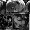
TTE is routinely performed before implantation of LVAD. Any significant left-to-right shunt caused by patent foramen ovale (PFO) or ASD should be detected and reported to the surgical team since lowering LA and LV pressure after LVAD implantation may cause significant right-to-left shunting leading to oxygen desaturation in the systematic circulation. Aortic regurgitation should be assessed. Significant aortic regurgitation leads to a ‘‘blind’’ loop of flow in which blood enters the LVAD from LV and then is pumped into the ascending aorta but flows back into LV through the regurgitant aortic valve. In this situation, a high-power LVAD may not produce inadequate forward cardiac output due to a “futile circulation”. Preexisting intracardiac thrombus may increase the risk of stroke during LV cannulation. In patients with a severely decreased LVEF and/or an LV aneurysm a microbubble contrast TTE study is often used to rule out LV thrombus ( Fig. 14.5 ) prior to the implantation of LAVD. Cardiac CT may be used for confirming apical thrombus. If LV thrombus is identified, the implanting surgeon should be made aware of its size and location so that the thrombus can be carefully removed during device implantation. Intraoperative transesophageal echocardiography is often used during LAVD implantation procedure. For some patients with atrial fibrillation, who are at increased risk for thrombus formation in the LA appendage, TEE may be required for a complete intracardiac thrombus workup.

Before device implantation, echocardiography may identify some echocardiographic features to predict significant MR post-LVAD implantation. Pre-LVAD posterior displacement of mitral leaflets was associated with postoperative significant functional MR, which may not always respond to simple volume reduction and unload of the ventricle.
TTE is routinely used for the evaluation of right ventricular (RV) function. Severe RV dysfunction may impact on outcome post-device implantation. The presence of severe biventricular failure may alter device selection. RV function is often assessed by visual estimation rather than quantitative measurements due to the limitations of current technology and/or poor acoustic windows. Therefore, experienced imagers are important for the success of the MCSD program. CMR can be used for quantitative measurements of RV volume and ejection fraction before LVAD implantation, if clinically needed.
After a durable MCSD is implanted, careful management by a heart failure team is essential to reduce complications. Cardiac imaging is important for monitoring device function and evaluating potential complications. LVAD support can be optimized using specific echocardiographic protocols. Multimodality imaging should be fully integrated into the heart failure program to assess the following clinical conditions after implantation of durable MCSD.
Hypovolemia may cause low cardiac output and hypotension. The combinations of low LVAD pump flow with normal LVAD power utilization in the presence of low filling pressures and hypotension highly suggest hypovolemia. Echocardiography may demonstrate the presence of small RV and LV cavity size and relatively small diameter of the inferior vena cava.
Assessment of LV function after LVAD is important but challenging due to interference of TTE imaging by cannula position and limited postoperative acoustic windows. The degree and condition of LV unloading or decompression should be carefully evaluated. The degree of MR and the position of the interventricular septum may be used to estimate LV decompression. An interventricular septum bowing to the right ventricle often indicates increased LV pressure (inadequate decompression, see Fig. 14.6A ). An increase in pump speed may improve LV decompression and reduce LV size, and the interventricular septum returned to the neutral position (see Fig. 14.6B ). Echocardiographic contrast agents may be safely used during LVAD support. LVEF can be estimated, but it may overestimate myocardial contractility as LV is unloaded by MCSD. Ventricular fibrillation may occur during LAVD support without a notice by a patient. TTE may show minimal or no LV wall motion. Ventricular fibrillation should be cardioverted.