FIGURE 17.47 Synovial sarcoma. Axial T1-weighted A: and fat-suppressed T2-weighted images B: show an ill-defined nonspecific mass on the T1 image and heterogeneously bright mass on the T2 image (arrow).
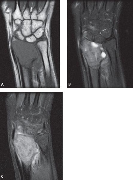
FIGURE 17.48 Giant cell tumor. Coronal T1-weighted A: fat-suppressed T2-weighted B: and fat-suppressed postcontrast T1-weighted images C: show a lytic expansile mass at the distal radius. Note that on the T2 sequence, the lesion shows mostly decreased T2 signal.
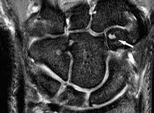
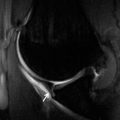
FIGURE 17.49 Intraosseous cyst. Axial fat-suppressed T2-weighted shows a well-defined hyperintensity within the trapezoid bone (arrow) in an asymptomatic individual.
Interosseous Ganglia and Carpal Cysts
Interosseous ganglia can result from extension of an adjacent soft tissue ganglion or they may be primary, unrelated to any soft tissue abnormalities (Fig. 17.49) (45). Interosseous ganglia are usually solitary and painful and are occasionally surgically removed.
Multiple nonspecific round T2 hyperintense lesions in the carpal bones are often seen on MRI. With the more frequent use of MRI in the evaluation of arthritis, it has become apparent that many patients have small carpal cysts that are not visible on radiography. These lesions should not be confused with erosions because they are frequently found in asymptomatic subjects (45).
References
1. Khan KM, Cook JL, Maffulli N, et al. Where is the pain coming from in tendinopathy? It may be biochemical, not only structural, in origin. Br J Sports Med. 2000;34:81–83.
2. Cook JL, Feller JA, Bonar SF, et al. Abnormal tenocyte morphology is more prevalent than collagen disruption in asymptomatic athletes’ patellar tendons. J Orthop Res. 2004;22:334–338.
3. Resnick D. Diagnosis of Bone and Joint Disorders. Diagnosis of Bone and Joint Disorders. 4th ed. Philadelphia, Pa: WB Saunders Company; 2002:3028.
4. Bencardino JT. MR imaging of tendon lesions of the hand and wrist. Magn Reson Imaging Clin N Am. 2004;12:333–347, vii.
5. Glajchen N, Schweitzer M. MRI features in de Quervain’s tenosynovitis of the wrist. Skeletal Radiol. 1996;25:63–65.
6. de Lima JE, Kim HJ, Albertotti F, et al. Intersection syndrome: MR imaging with anatomic comparison of the distal forearm. Skeletal Radiol. 2004;33:627–631.
7. Pantukosit S, Petchkrua W, Stiens SA. Intersection syndrome in Buriram Hospital: a 4-yr prospective study. Am J Phys Med Rehabil. 2001;80:656–661.
8. Heidemann J, Gausepohl T, Pennig D. Narrowing of the third extensor tendon compartment in minimal displaced distal radius fractures with impending rupture of the EPL tendon [in German]. Handchir Mikrochir Plast Chir. 2002;34:324–327.
9. Allende C, Le Viet D. Extensor carpi ulnaris problems at the wrist—classification, surgical treatment and results. J Hand Surg (Br). 2005;30:265–272.
10. Drape JL, Tardif-Chastenet de Gery S, Silbermann-Hoffman O, et al. Closed ruptures of the flexor digitorum tendons: MRI evaluation. Skeletal Radiol. 1998;27:617–624.
11. Goldfarb CA, Yin Y, Gilula LA, et al. Wrist fractures: what the clinician wants to know. Radiology. 2001;219:11–28.
12. Cerezal L, Abascal F, Canga A, et al. Usefulness of gadolinium-enhanced MR imaging in the evaluation of the vascularity of scaphoid nonunions. AJR Am J Roentgenol. 2000;174:141–149.
13. Timins ME, Jahnke JP, Krah SF, et al. MR imaging of the major carpal stabilizing ligaments: normal anatomy and clinical examples. Radiographics. 1995;15:575–587.
14. Zanetti M, Hodler J, Gilula LA. Assessment of dorsal or ventral intercalated segmental instability configurations of the wrist: reliability of sagittal MR images. Radiology. 1998;206:339–345.
15. Lichtman DM, Mack GR, MacDonal RI, et al. Kienbock’s disease: the role of silicone replacement arthroplasty. J Bone Joint Surg Am. 1977;50:899–908.
16. Cerezal L, del Pinal F, Abascal F. MR imaging findings in ulnar-sided wrist impaction syndromes. Magn Reson Imaging Clin N Am. 2004;12:281–299, vi.
17. Tomaino MM. Ulnar impaction syndrome in the ulnar negative and neutral wrist. Diagnosis and pathoanatomy. J Hand Surg (Br). 1998;23:754–757.
18. Mellado JM, Calmet J, Domenech S, et al. Clinically significant skeletal variations of the shoulder and the wrist: role of MR imaging. Eur Radiol. 2003;13:1735–1743.
19. Friedman SL, Palmer AK. The ulnar impaction syndrome. Hand Clin. 1991;7:295–310.
20. Bell MJ, Hill RJ, McMurtry RY. Ulnar impingement syndrome. J Bone Joint Surg Br. 1985;67:126–129.
21. Escobedo EM, Bergman AG, Hunter JC. MR imaging of ulnar impaction. Skeletal Radiol. 1995;24:85–90.
22. Malik AM, Schweitzer ME, Culp RW, et al. MR imaging of the type II lunate bone: frequency, extent, and associated findings. AJR Am J Roentgenol. 1999;173:335–338.
23. Sugimoto H, Takeda A, Hyodoh K. Early-stage rheumatoid arthritis: prospective study of the effectiveness of MR imaging for diagnosis. Radiology. 2000;216:569–575.
24. Peterfy CG. MRI of the wrist in early rheumatoid arthritis. Ann Rheum Dis. 2004;63:473–477.
25. Tehranzadeh J, Ashikyan O, Dascalos J, et al. MRI of large intraosseous lesions in patients with inflammatory arthritis. AJR Am J Roentgenol. 2004;183:1453–1463.
26. Yu JS, Chung C, Recht M, et al. MR imaging of tophaceous gout. AJR Am J Roentgenol. 1997;168:523–527.
27. Barakat MS, Schweitzer ME, Morisson WB, et al. Reactive carpal synovitis: initial experience with MR imaging. Radiology. 2005;236:231–236.
28. Graif M, Schweitzer ME, Deely D, et al. The septic versus nonseptic inflamed joint: MRI characteristics. Skeletal Radiol. 1999;28:616–620.
29. Hopkins KL, Li KC, Bergman G. Gadolinium-DTPA-enhanced magnetic resonance imaging of musculoskeletal infectious processes. Skeletal Radiol. 1995;24:325–330.
30. Wang HT, Sunil TM, Kleinert HE. Multiple unusual complications after extensive chronic sarcoid tenosynovitis of the hand: acasereport. J Hand Surg (Am). 2005;30:610–614.
31. Oneson SR, Scales LM, Erickson SJ, et al. MR imaging of the painful wrist. Radiographics. 1996;16:997–1008.
32. Steinbach LS, Smith DK. MRI of the wrist. Clin Imaging. 2000;24:298–322.
33. Garcia J, Bianchi S. Diagnostic imaging of tumors of the hand and wrist. Eur Radiol. 2001;11:1470–1482.
34. Cardinal E, Buckwalter KA, Braunstein EM, et al. Occult dorsal carpal ganglion: comparison of US and MR imaging. Radiology. 1994;193:259–262.
35. Anderson SE, Steinbach LS, Stauffer E, et al. MRI for differentiating ganglion and synovitis in the chronic painful wrist. AJR Am J Roentgenol. 2006;186:812–818.
36. Shankman S, Kolla S, Beltran J. MR imaging of tumors and tumor-like lesions of the upper extremity. Magn Reson Imaging Clin N Am. 2004;12:349–359.
37. de La Kethulle de Ryhove D, De Beuckeleer L, De Schepper A. Magnetic resonance imaging of soft tissue tumors of the hand and wrist [in French]. J Radiol. 2000;81:493–507.
38. Toms AP, Anastakis D, Bleakney RR, et al. Lipofibromatous hamartoma of the upper extremity: a review of the radiologic findings for 15 patients. AJR Am J Roentgenol. 2006;186:805–811.
39. Zeiss J, Jakab E, Khimji T, et al. The ulnar tunnel at the wrist (Guyon’s canal): normal MR anatomy and variants. AJR Am J Roentgenol. 1992;158:1081–1085.
40. Bordalo-Rodrigues M, Amin P, Rosenberg ZS. MR imaging of common entrapment neuropathies at the wrist. Magn Reson Imaging Clin N Am. 2004;12:265–279, vi.
41. Zeiss J, Guilliam-Haidet L. MR demonstration of anomalous muscles about the volar aspect of the wrist and forearm. Clin Imaging. 1996;20:219–221.
42. Timins ME. Muscular anatomic variants of the wrist and hand: findings on MR imaging. AJR Am J Roentgenol. 1999;172:1397–1401.
43. Timins ME. Osseous anatomic variants of the wrist: findings on MR imaging. AJR Am J Roentgenol. 1999;173:339–344.
44. Capelastegui A, Astigarraga E, Fernandez-Canton G, et al. Masses and pseudomasses of the hand and wrist: MR findings in 134 cases. Skeletal Radiol. 1999;28:498–507.
45. Magee TH, Rowedder AM, Degnan GG. Intraosseous ganglia of the wrist. Radiology. 1995;195:517–520.
Distal Interphalangeal Joint Anatomy
The distal interphalangeal joint is formed by the junction of the base of the distal phalanx with the head of the middle phalanx. The head of the middle phalanx has a bicondylar smooth surface with an intercondylar depression. It engages an elevated anteroposterior ridge that comprises the base of the distal phalanx. The articular surface of the head of the middle phalanx extends dorsally for an extensive distance, reflecting the passive hyperextension possible at the joint. Volarly, the articular surface permits flexion to 90 degrees. The articulation is held together by a capsule that surrounds the cartilaginous surfaces of the joint.
The capsular anatomy of this articulation is complicated by contributions from both ligaments and tendon attachments, which serve to stabilize the joint, hence the term tendinocapsuloligamentous unit. The capsule is reinforced laterally by thick collateral ligaments that insert into the sides of the head of the middle phalanx and run in a distal and volar direction for insertion into the laterovolar tubercle of the base of the distal phalanx (Fig. 18.1). Accessory collateral ligaments are more volar and extend from the sides of the phalangeal head proximally to the sides of the palmar plate distally. The palmar plate provides for volar stability and serves as a floor for the flexor digitorum profundus tendon. This plate of fibro-cartilage blends imperceptibly into the nonarticular surface of the base of the distal phalanx and coalesces with the fibers of the flexor digitorum profundus (FDP) tendon attachment. Proximally the plate is attached to the neck of the middle phalanx, but there are no “check rein” ligaments, so hyperextension of the joint is permitted (Fig. 18.2).
The fibrous tunnel of the flexor tendons, the pulley system, also participates in the formation of the tendinocapsuloligamentous unit of the distal interphalangeal, (DIP) adhering to the palmar plate. The insertion of the FDP adds further to the complexity of the capsular anatomy. Before its insertion into the base of the distal phalanx, the FDP tendon fans out over the entire width of the joint and can divide longitudinally into two terminal tendons instead of one. The divided tendon is inserted into the entire width of the base of the distal phalanx, blending with the distal fibers of the palmar plate, periosteum, and even sending fibrous extensions into the fat pad of the finger tip.
Over the joint, the FDP is completely free and glides smoothly within its protective fibrous tunnel. It is connected with the palmar plate through nonrestricting short vincula tendinum for the purposes of blood supply. Immediately beneath the palmar plate, numerous small foramina can be identified at the volar base of the distal phalanx. These foramina permit the passage of multiple nutrient arteries that may prove more important in vascularizing the middle phalanx than the conventional nutrient artery that enters its shaft.
The dorsum of the joint has no reinforcing ligament, although the terminal part of the extensor apparatus of the finger serves as a reinforcement firmly adhering to the capsule between the collateral ligaments. The insertion of the extensor apparatus is broad-based, blending into the capsular fibers of the DIP as well as into adjacent periosteum.
Both the volar and dorsal aspects of the joint capsule display intra-articular thickening. The dorsal capsular thickening protrudes into the dorsal joint between the base of the distal phalanx and the head of the proximal phalanx. The volar thickening fills the space between the volar part of the distal phalanx and the head of the middle phalanx. The interior of the joint is covered with a thin synovial membrane that can protrude into the joint in the form of small diverticuli.
To reinforce the concept that every articulation is surrounded by a fibrous envelope, even the extensor apparatus and the FDP are connected by a network of fibers that run parallel to the collateral ligaments. This fibrous network extends between the dorsal extensor apparatus and the volar FDP. They are more superficial in nature than the collateral ligaments and serve to anchor the extensor apparatus to the FDP in the region of the DIP without restricting motion.
On MR images, normal collateral ligaments appear as sharply defined, linear, low-signal–intensity bands. They are optimally visualized in the coronal imaging plane. The volar plate is triangular in morphology and low in signal intensity. It is best identified in the sagittal imaging plane. The fibrous tunnel of the flexor tendons (at the level of the DIP, the A5 pulley) is a low-signal–intensity band that extends from the tendon to the volar plate. This structure is best localized in the axial imaging plane.
Proximal Interphalangeal Joint Anatomy
The proximal interphalangeal joint differs from DIP in the connections between the ligaments and the extensor and flexor systems. The capsule of this joint is reinforced by two sets of collateral ligaments (radial and ulnar), corresponding accessory collateral ligaments, the volar plate, and extensor mechanism (Fig. 18.3).
The collateral ligament complex is present at both the radial and ulnar sides of the articulation and consists of the collateral ligament proper as well as an accessory collateral ligament (Fig. 18.4). The collateral ligaments begin at the dorsolateral and dorsomedial aspects of the head of the proximal phalanx and insert at the volar lateral and medial aspects of the base of the middle phalanx, respectively. The accessory collateral ligaments share a common proximal site of attachment but insert at the volar plate. The proper collateral ligament is taut in flexion, whereas the accessory collateral ligament is taut in extension.
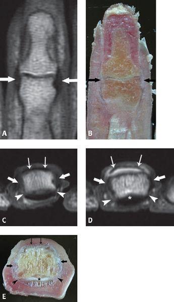
FIGURE 18.1 Distal interphalangeal (DIP) collateral ligament anatomy. A: T1-weighted coronal MR image shows the collateral ligaments (arrows) coursing from the head of the middle phalanx proximally to the laterovolar tubercles of the distal phalanx. B: Corresponding specimen photograph of the DIP in the coronal plane shows the glistening white appearance of the ligament fibers (thick arrows). C: T1-weighted axial MR image shows the position of the collateral ligaments (arrows), the posterior extension of the accessory collateral ligaments (arrowheads) as well as the broad based attachment of the distal extensor tendon (thin arrows). D: T1-weighted fat-suppressed axial MR image acquired after arthrography and E: corresponding specimen photograph show the collateral ligaments (arrows), the accessory collateral ligaments (arrowheads), and the attachment of the distal extensor tendon (thin arrows) dorsally and the volar plate (asterisk) at the palmar distal tuft.
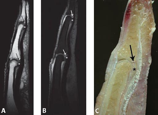
FIGURE 18.2 Volar plate anatomy. A: T1-weighted sagittal MR image and B: corresponding T1-weighted fat-suppressed sagittal MR image acquired after arthrography demonstrates the capsular volar plate attachments (asterisk) at both interphalangeal joints of the finger. Recesses exist between the volar plates and their respective osseous attachments (arrows). C: Corresponding specimen photograph profiles both the prominent tissue of the volar plate (asterisk) as well as the recess at its distal osseous attachment (arrow).
The volar plate is a thick fibrocartilaginous structure that constitutes the palmar aspect of the proximal interphalangeal (PIP) joint capsule. Distally, there is no significant attachment of the volar plate to the middle phalanx. In the central portion of the base of the middle phalanx, the volar plate is loosely attached to the periosteum. This results in the formation of a meniscus of fibrocartilage comprising the volar plate with a recess between it and the volar articular surface of the middle phalanx. This anatomic arrangement permits the plate to retract from the base of the middle phalanx when the joint is flexed. Proximally, the volar plate is firmly anchored to the bone just inside the second annular pulley (A2) and confluent with the origin of the first cruciate pulley (C1). The attachment of the volar plate to the proximal phalanx is more elastic than in the DIP and is U-shaped as a result of two lateral bands, which are called the “check rein” ligaments (Fig. 18.5). The volar plate prevents hyperextension of the PIP joint.
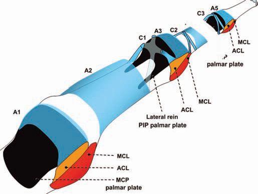
FIGURE 18.3 Anatomy of the proximal interphalangeal (PIP). The capsular anatomy of the volar aspect of the finger is illustrated emphasizing the intimate spatial relationship of capsular and ligamentous structures with the pulley system of the flexor tendon. MCL, main collateral ligament; ACL, accessory collateral ligament; A1, annular pulley at level of metacarpophalangeal; A2, annular pulley at level of proximal phalanx; A3, annular pulley at level of PIP; A4, annular pulley at level of middle phalanx; A5, annular pulley at level of distal interphalangeal; C1, first cruciform pulley; C2, second cruciform pulley; C3, third cruciform pulley).
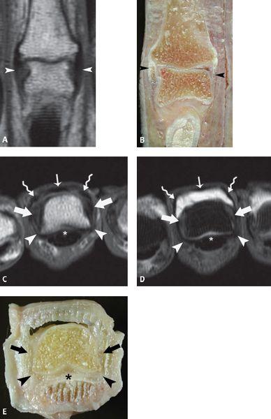
FIGURE 18.4 Proximal interphalangeal (PIP) collateral ligament anatomy. A: T1-weighted coronal MR image shows the linear, lowsignal–intensity appearance of the collateral ligaments (arrowheads). B: Corresponding specimen photograph of the PIP in the coronal plane demonstrates the gross appearance and course of the ligaments (arrowheads). C: T1-weighted axial MR image and D: T1-weighted fat-suppressed axial image acquired after arthrography emphasize the location of the collateral ligaments (thick arrows), the accessory collateral ligaments, the volar plate (asterisk), the central slip (thin arrow) as well as the lateral slips (curved arrows) of the extensor mechanism. E: Corresponding specimen photograph of the PIP in the axial plane shows the position of the collateral ligaments (arrows), the accessory collateral ligaments (arrowheads), and the volar plate (asterisk).
Dorsally, the PIP joint is stabilized by the dorsal extensor apparatus, including the central slip inserting on the dorsal tubercle of the middle phalanx and lateral slips that are connected by retinacular ligaments (Fig. 18.6). The transverse retinacular ligament is composed of thick, strong fascia that originates from the volar aspect of the capsule in the flexor tendon sheath. Most of the fibers insert in the lateral margin of the lateral tendon, but a few pass dorsally over the extensor tendon and become continuous with those of the opposite side. All fibers of this ligament abut the capsule of the PIP joint, coursing from a volar origin to a dorsal insertion. The ligament seems to act as a stabilizer for the lateral tendon. It also pulls the lateral tendon volar when the finger is flexed. The second retinacular ligament is that of the oblique retinacular ligament. In contrast to the fibers of the transverse retinacular ligament, those of the oblique retinacular ligament appear tendinous in nature. Two parts of the oblique retinacular ligament have been described: the longitudinal cord and the oblique cord. They form a narrow, strong tendinous band. The former extends between the volar lateral ridge of the proximal phalanx and inserts at the level of the collateral ligaments of the PIP (Fig. 18.7). The oblique cord is thinner and runs from the lateral capsule of the PIP joint dorsally to the lateral bands of the extensor tendons at the level of the middle phalanx. It is visualized in only 50% of patients. Together the components of the oblique retinacular ligament pass parallel to the lateral margin of the lateral extensor tendon and along the long axis of the phalanx. This ligament passes volar to the axis of rotation of the PIP. Although many variations in the anatomy of this ligament can occur, the ulnar aspect of the ring finger proves most constant (1, 2).
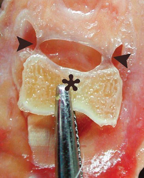
FIGURE 18.5 Check rein ligament of the proximal interphalangeal (PIP) joint. Dissected PIP joint shows the proximal attachment of the volar plate to the proximal phalanx (asterisk). The attachment is U-shaped as a result of the presence of two lateral bands (arrowheads), the “check rein” ligaments, that afford a more elastic nature to this joint.
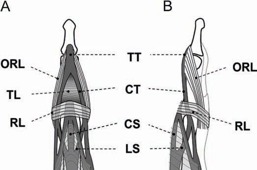
FIGURE 18.6 Transverse and oblique retinacular ligaments of the proximal interphalangeal (PIP) joint. A: Frontal and B: lateral diagrams of the PIP and distal interphalangeal joint profile the anatomy of the retinacular ligaments and their relationship with the extensor hood. TT, terminal tendon; ORL, oblique retinacular ligament; TL, triangular ligament; CT, central tendon; RL, transverse retinacular ligament; CS, central slip; LS, lateral slip.
On MR images, normal collateral ligaments appear as sharply defined low-signal–intensity bands that extend from the proximal phalanx to the middle phalanx. They are optimally visualized in the coronal imaging plane. The volar plate is triangular in morphology, low signal intensity, and best identified in the sagittal imaging plane. The pulley system of the flexor tendon is best identified in the axial imaging plane. The anchors of the pulley are linear and low in signal intensity, seen extending from the tendon to the osseous or soft tissue site of attachment. The MRI findings of the check rein ligaments have not been described.
Lesser Metacarpophalangeal Joint Anatomy
Although the supporting structures of the metacarpophalangeal joint (MCP) and the PIP joint are similar, the osseous anatomy of the multiaxial condyloid joint permits flexion, extension, abduction, adduction, and, to a lesser degree, circumduction. The capsular structures of this joint include two collateral ligaments, two accessory collateral ligaments, and a volar plate. Although these structures do stabilize the joint, it is the contraction of the intrinsic muscles of the hand, the tautness of the flexor tendons, and extensor apparatus that prove most important in joint stability (Fig. 18.8).
The collateral ligaments are situated on the radial and ulnar side of each joint and are quite thick. Reinforcing the capsule, these ligaments are taut in flexion and relaxed in extension. The collateral ligaments arise in a depression of the lateral subcapital area of the metacarpal, then run distally toward the base of the proximal phalanx and fan out widely from the lateral tubercle of the base of the proximal phalanx (Fig. 18.9). The accessory collateral ligament arises in the same depression as the main collateral ligaments but in a more palmar location. Their proximal attachment is inseparable from the main collateral ligaments. The accessory collateral ligament extends distally to the volar plate. This structure is taut in extension and more relaxed in flexion. Dorsally, the collateral ligament blends with the dorsal capsule of the MCP joint (Fig. 18.8).
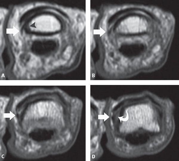
FIGURE 18.7 Oblique retinacular ligament of the proximal interphalangeal (PIP) joint. A–D: Sequential T1-weighted axial MR images of the PIP joint from proximal (A) todistal (D) of the index finger show the course of the ligament (arrow) extending from the volar lateral ridge of the proximal phalanx proximally (arrowhead) to the region of the collateral ligament distally (curved arrow).
Although it has been shown that the main collateral ligaments about the MCP joint of the fingers are best evaluated in the axial imaging plane in the flexed finger, the authors find the coronal imaging plane in the neutral position to be a practical and useful imaging plane for collateral ligament assessment (3). This is particularly true in the acutely injured finger, in which imaging in the flexed position may not be possible. The accessory bands of the collateral ligaments are best seen in the axial imaging plane in the extended finger.
The volar plate is firmly attached into the volar base of the proximal phalanx. Proximally, it thins out into a flexible membranous ligament that is attached to the volar side of the MCP neck. The volar plate, with its two accessory collateral ligaments, enlarges the joint cavity permitting the head of the MCP to remain in the articular cavity when the joint is in full flexion. A recess can be identified between the two accessory collateral ligament attachments. Although the dorsal surface of the volar plate is in contact with the head of the metacarpal, the volar surface of this ligament is in contact with the flexor tendons. The digital flexor tendon sheaths are maintained against the volar plate by the A1 pulley. The pulley attaches to the junction of the volar plate and the deep transverse metacarpal ligament. The volar plates are connected from the index finger to the fifth finger by the deep transverse metacarpal ligament. This structure continues into the palm of the hand, becoming thinner and blending with the anterior fascia that covers the interosseous muscles. Volar to the transverse metacarpal ligament are the lumbrical muscles, dorsal to the ligament past the tendons of the interosseous muscles.
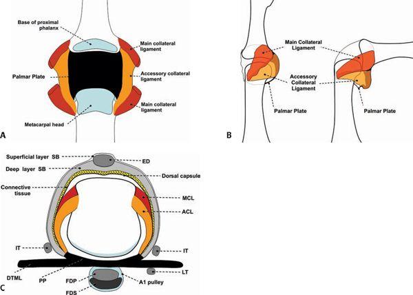
FIGURE 18.8 Lesser metacarpophalangeal joint anatomy. A: The dorsal capsule has been removed, the main collateral ligament cut, and the metacarpophalangeal joint opened to show the relationship of the accessory and main collateral ligaments of the articulation. B: Similar to the distal interphalangeal and proximal interphalangeal, the main collateral ligament is relaxed in extension and taut in flexion. In addition, the axial images in the flexed position allow for visualization of the main collateral ligaments along their long axis. C: The tendinocapsuloligamentous unit of the metacarpophalanageal is quite complex as a result of the interplay of numerous soft tissue supporting structures. SB, sagittal band; ED, extensor digitorum; MCL, main collateral ligament; ACL, accessory collateral ligament; IT, interosseous tendon; PP, palmar plate; DTML, deep transverse metacarpal ligament; LT, lumbrical tendon; FDP, flexor digitorum profundus; FDS, flexor digitorum superficialis.
Transverse T1-weighted spin-echo MR images and arthrograms of joints in extension enable the best visualization of the axial extent of the volar plate, the deep transverse metacarpal ligament, and the A1 pulley attaching to the volar plate. Sagittal T1-weighted spin-echo MR arthrograms of the joints in either flexion or extension enable the best delineation of the shape of the body of the volar plate and its distal attachments as well as the central recess (Fig. 18.10) (3).
In contrast to the PIP and DIP, in which tendons adhere intimately to the capsule, only loose connections exist between the palmar surface of the extensor apparatus and the dorsal aspect of the capsule. These include the sagittal bands, thin bands that extend from the common extensor tendons to the junction of the volar plate and the deep transverse metacarpal ligament (4). The sagittal band can be divided into superficial and deep layers, the former a very thin structure that runs over the extensor tendon joining the deep layer on each side of the tendon. The sagittal bands course between the interosseous tendons and the main collateral ligaments. The connection between the capsule of the joint and the extensor expansion at the level of the MCP appears to serve a double role: to reinforce the to-and-fro action of the extensor expansion over the MCP and to stabilize the mid-band of the extensor over the center of the joint. Conventional and arthrographic transverse T1-weighted spin-echo MR images of the fingers in extension are the best way to analyze the sagittal bands.
Distal to the sagittal bands, transversely oriented fibers form a triangular lamina that join the tendons of the lumbrical muscles. These fibers are best evaluated on conventional and arthrographic T1-weighted spin-echo MR images of the fingers in extension.
Interphalangeal Joint of the Thumb
The interphalangeal joint of the thumb is formed by the base of the distal phalanx and the head of the proximal phalanx. It is a hinge joint with a strong capsule and ligaments permitting minimal lateral motion (Fig. 18.11). The capsule is reinforced by two collateral ligaments and their extensions, the accessory collateral ligaments, into the volar fibrocartilaginous plate. The tendon of the flexor pollicis longus passes over the plate to reach its insertion, which occurs over a wide and sometimes deeply excavated surface of the volar phalangeal base. A sesamoid embedded in the tendon proximal to the base of the phalanx is occasionally present. At the dorsal aspect of the joint, the extension of the fibers of extensor pollicis longus and, in some cases, the combined fibers of extensor pollicis longus and brevis adhere to the capsule of the joint.
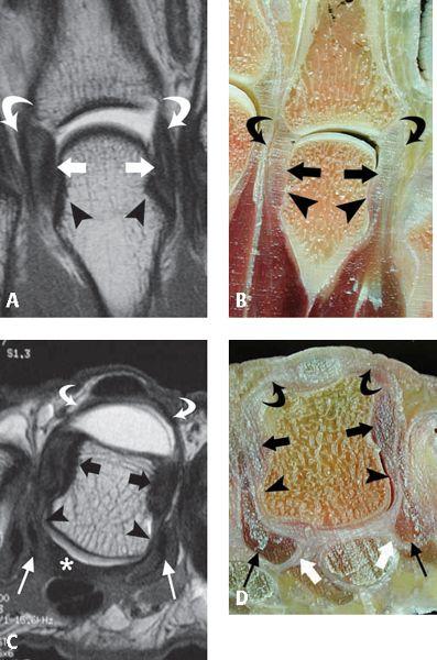
FIGURE 18.9 Collateral ligament anatomy of the metacarpophalangeal joint. A: T1-weighted coronal MR image acquired after arthrography and B: corresponding specimen photograph show the collateral ligaments (arrows) attaching proximally in a depression of the lateral subcapital area of the metacarpal (arrowheads). The close spatial relationship of the superficial interosseous tendon (curved arrow) to the collateral ligaments (arrows) is noted. C: T1-weighted axial MR image acquired after arthrography and D: corresponding specimen photograph show the continuous nature of the capsular structures of the joint, including the sagittal bands (curved arrows), the collateral ligaments (thick black arrows), the accessory collateral ligaments (arrowheads), and the volar plate (asterisk). The interosseous tendons (thin arrows) and the deep transverse metacarpal ligament (thick white arrows) are also noted.
Metacarpophalangeal Joint Anatomy of the Thumb
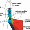
The MCP joint of the thumb is a condylar-type articulation that allows several types of motion, including flexion and extension. This joint is formed by the connection of the metacarpal head and the base of the proximal phalanx with the addition of two sesamoid bones. The capsule uniting the osseous structures is thin dorsally and thicker on the volar surface (Fig. 18.12). It is reinforced on each side by collateral and accessory collateral ligaments (Fig. 18.13). Distally, each collateral ligament attaches both to the base of the proximal phalanx and is sometimes referred as to the cord portion of the collateral ligament complex. The accessory collateral ligament extends to the volar surface of the joint to the region of the capsule where the sesamoids are embedded. The portion of the capsule that accommodates the sesamoids is referred to as the intersesamoid ligament. It has also been referred to as the volar plate of the MCP joint. In addition, at the palmar aspect of the joint, there are palmar ulnar and palmar radial longitudinal ligaments that reinforce the posterior capsule (Fig. 18.12). The tunnel of the flexor pollicis longus is intimately connected to the volar plate. The dorsum of the joint is in contact with the tendinous attachments of the extensor pollicis longus and brevis (long muscles of the thumb) as well as the abductor pollicis brevis and flexor pollicis brevis. The abductor pollicis brevis and flexor pollicis brevis, in conjunction with the opponens pollicis, are referred to as the short muscles of the thumb or the muscles of the thenar eminence.
Although the distal attachment sites of abductor pollicis brevis and the flexor pollicis brevis have an intimate spatial relationship with the radial capsule of the thumb, it is the relationship of the adductor pollicis attachment to the ulnar capsule that holds clinical significance. It is the deepest muscle of the thenar eminence and arises by two heads, transverse and oblique, that ultimately converge to a short tendon that attaches at the ulnar side of the thumb. This attachment is superficial to the ulnar collateral ligament and must be closely examined in the setting of ulnar collateral ligament injury (Fig. 18.12).
Carpometacarpal Joint Anatomy of the Thumb
The trapeziometacarpal (TMC) joint is described as a sellar joint between the first metacarpal base and the trapezium. The mobility of this articulation is a reflection of its extensive articular surface and thick but loose fibrous capsuloligamentous structure (5). The TMC is a common site of trauma as well as chronic degenerative change in the absence of a history of an inciting traumatic event. The TMC joint is the site most frequently requiring surgical reconstruction in the osteoarthritic upper extremity (5, 6). Anatomic studies of the TMC joint have emphasized the role of the stabilizing ligaments (6–10).
The following six ligaments about the TMC joint are generally recognized: the dorsoradial ligament (DRL), the posterior oblique ligament (POL), the intermetacarpal ligament (IML), the ulnar collateral ligament (UCL), the superficial anterior oblique ligament (sAOL), and the deep anterior oblique ligament (dAOL). The anterior oblique ligament is also referred as to the beak or volar ligament. The DRL, POL, and IML are attached to the dorsal aspect of the joint; the UCL, sAOL, and dAOL to the volar aspect of the TMC joint (Fig. 18.14).
The DRL is a wide and short-spanning capsular ligament that attaches to the dorsoradial tubercle of the trapezium and dorsal edge of the first metacarpal base (Fig. 18.15). Dorsal instability is usually the result of disruption of this ligament. The POL is a capsular ligament located deep to the extensor pollicis longus tendon. It attaches to the dorsoulnar side of the trapezium and the dorsoulnar aspect of the first metacarpal in conjunction with the DRL (Fig. 18.16). The IML is an extracapsular ligament, which arises from the dorsoradial aspect of the second metacarpal, radial to the extensor carpi radialis longus tendon insertion, and runs toward the volar–ulnar tubercle of the first metacarpal base (Fig. 18.17).
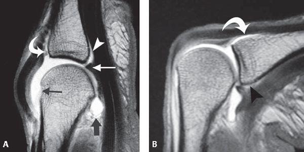
FIGURE 18.10 Volar plate anatomy of the metacarpophalangeal joint. A: T1-weighted sagittal MR image acquired after arthrography in the extended finger shows the volar plate (thin white arrow), the distal recess of the volar plate (arrowhead), the loose proximal recess (thick black arrow) as well as the distal extent of the dorsal joint capsule (curved arrow). The normal bare area of the metacarpal (think black arrow) is noted between the articular surface and the proximal capsular attachment. B: T1-weighted sagittal MR image acquired after arthrography in the flexed finger shows the compressed distal recess of the volar plate (arrowhead) as well as the distal extent of the dorsal recess (curved arrow).
At the volar side of the joint, an extracapsular ligament, the UCL originates from the distal margin of the flexor retinaculum at its ulnar aspect and inserts superficial and ulnar to the sAOL on the volar–ulnar tubercle of the first metacarpal base. It typically overlaps the sAOL by 2 to 3 mm (Fig. 18.18). The sAOL is a capsular ligament that originates from the volar tubercle of the trapezium 0.5 mm proximal to its articular surfaced and from the volar tubercle of the first metacarpal 2 mm distal to its articular margin. This relationship creates a capsular recess between the sAOL and the first metacarpal (Fig. 18.19). It is superficial to the dAOL and has been described as running in a “curtain-like” fashion (7). The dAOL is an intracapsular ligament that inserts at the articular margins of the trapezium and first metacarpal deep to the sAOL (Fig. 18.19). The dAOL, in conjunction with the sAOL, shares the function of stabilizing the TMC joint against volar subluxation of the metacarpal. Because of the dAOL, Bennett’s fracture results in a ligament avulsion rather than pure dislocation. The volar fracture fragment of the Bennett lesion remains attached to the trapezium by the dAOL. Furthermore, laxity of the dAOL has been implicated as an initiating factor in the development and progression of degenerative joint disease at the TMC joint.
In the experience of the authors, the DRL, POL, IML, sAOL, and dAOL are best visualized in the sagittal plane and the UCL is best visualized in the coronal plane. MR arthrography improves visualization of the IML, sAOL, dAOL, and UCL.
Pathology
Finger Proximal Interphalangeal Joint
Collateral Ligament Injury
Collateral ligament injuries appear to be the most common type of ligamentous insufficiency about the finger (11). Isolated injury to the collateral ligaments can occur in the absence of volar plate injury or joint dislocation. In a series of 30 such lesions, McCue et al. (11) documented that the index finger was most commonly injured. The generic “sprained finger” is usually a collateral ligament injury or volar plate injury (12, 13).
The mechanism for a collateral ligament injury includes an abducting or adducting force applied to the PIP joint in the extended finger. Three main injuries may arise in the collateral ligaments: a ligamentous sprain with no loss of articular stability, a partial ligamentous tear with laterolateral articular instability, and a complete ligamentous rupture with major instability and articular subluxation. Treatment may be surgical or conservative.
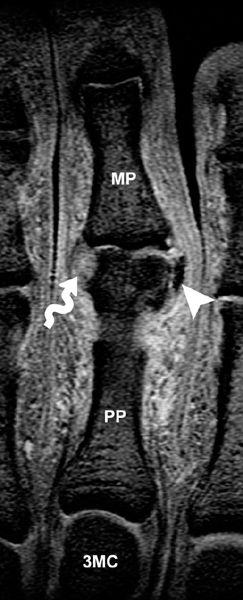
MRI allows diagnosis of collateral ligament injuries and is important because the examiner can easily convert a partial tear to a complete tear with overly vigorous testing for stability. MRI criteria for diagnosis of a ligament strain include a continuous ligament with surrounding edema in the soft tissues. A partial tear is represented by intrinsic signal intensity within the ligament on fluid-sensitive sequences that parallels that of joint fluid. No complete areas of discontinuity are identified (Fig. 18.20). Acute full-thickness collateral ligament tears show discontinuity, detachment, or thickening of the ligament together with increased intraligamentous signal intensity on T2-weighted images, suggesting the presence of hemorrhage or edema. Obliteration of the fat planes around the ligament and extravasation of joint fluid into the adjacent soft tissues may also be observed. Chronic tears can be more challenging to diagnose as a result of the lack of surrounding edema; however, thickening of the ligament resulting from scar formation can be seen. Alternatively, an attenuated ligament with a wavy contour can be encountered (12, 14, 15).
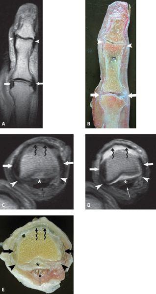
FIGURE 18.11 Collateral ligament anatomy of the interphalangeal (IP) joint of the thumb. A: T1-weighted coronal MR image and B: corresponding specimen photograph demonstrate the collateral ligaments at the IP joint (arrowheads) and the metacarpophalangeal joint (arrows). C: T1-weighted axial MR image before and D: after arthrography as well as E: corresponding specimen photograph show the collateral ligaments (arrows), the accessory collateral ligaments (arrowheads), the volar plate (asterisk), the flexor pollicis longus (thin arrow), and the extensor pollicislongus (curved arrow).
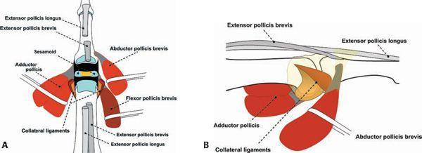
FIGURE 18.12 Anatomy of the posterior capsular complex of the metacarpophalangeal (MCP) of the thumb. A: This diagram emphasizes the complex spatial relationship of the soft tissue structures, including tendon attachments, about the posterior aspect of the thumb with the joint open to better appreciate the articular architecture. B: Like in the finger, collateral and accessory collateral ligaments are present at the MCP of the thumb. Similar to the relationship of the adductor pollicis aponeurosis and the ulnar collateral ligament on the ulnar side of the thumb, the abductor pollicis brevis attachment is just superficial to the radial collateral ligament complex.
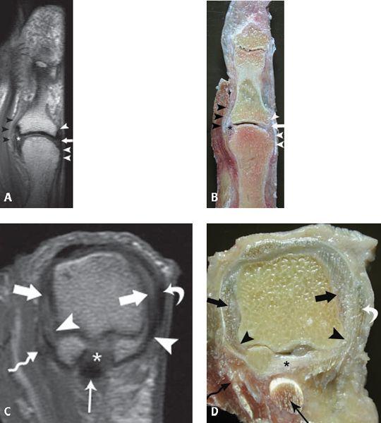
FIGURE 18.13 Anatomy of the metacarpophalangeal of the thumb. A: T1-weighted coronal MR image and B: corresponding specimen photograph show the ulnar collateral ligament (asterisk) and the closely apposed, superficial aponeurosis of the adductor pollicis longus (black arrowheads). A similar spatial relationship exists with the radial collateral ligament (arrow) and the superficial tendon of the abductor pollicis brevis (white arrowheads). C: T1-weighted axial MR image and D: corresponding specimen photograph demonstrate the main collateral ligaments (thick arrows), the accessory collateral ligaments (arrowheads), the aponeurosis of the adductor pollicis longus (curved arrow), the tendon of the abductor pollicis brevis (curved arrow), the intersesamoid ligament (asterisk), and the flexor pollicis longus (thin arrow).
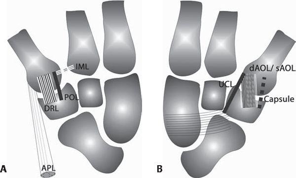
FIGURE 18.14 Anatomy of the carpometacarpal (CMC) of the thumb. A: Dorsal and B: palmar views of the CMC of the thumb profile the primary ligamentous structures of this complex articulation. IML, intermetacarpal ligament; POL, posterior oblique ligament; DRL, dorsoradial ligament; APL, tendon of abductor pollicis longus; UCL, ulnar collateral ligament; dAOL, deep fibers anterior oblique ligament; sAOL, superficial fibers anterior oblique ligament.
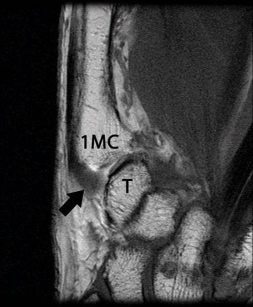
FIGURE 18.15 Dorsoradial ligament (DRL) of the carpometacarpal (CMC) of the thumb. T1-weighted coronal MR image after arthrography shows the dorsal aspect of the CMC joint. The DRL (arrow) is a wide and short-spanning capsular ligament that attaches to the dorsoradial tubercle of the trapezium (T) and the dorsal edge of the first metacarpal base (1MC).
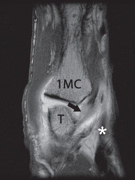
FIGURE 18.16 Posterior oblique ligament (POL) of the carpometacarpal of the thumb. T1-weighted sagittal MR image after arthrography profiles the POL (arrow) with its attachments to the first metacarpal base (1MC) and the trapezium (T) located deep to the extensor pollicis longus tendon (asterisk).
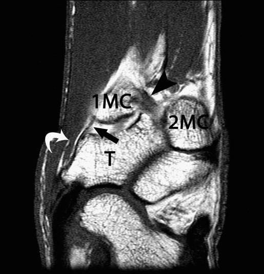
FIGURE 18.17 Intermetacarpal ligament (IML) of the carpometacarpal of the thumb. T1-weighted sagittal MR image after arthrography shows the course of the IML (arrowhead) extending obliquely between the volar–ulnar aspect of the first metacarpal base (1MC) to the dorsoradial aspect of the second metacarpal (2MC) and distal to the trapezium (T). The deep (arrow) and superficial (curved arrow) components of the anterior oblique ligament are also noted.
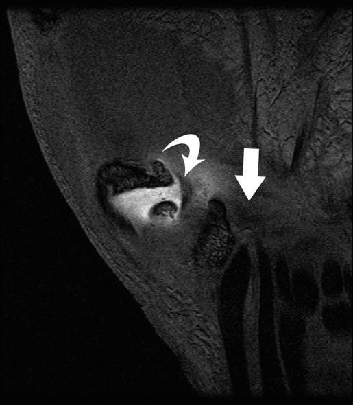
FIGURE 18.18 Ulnar collateral ligament (UCL) of the carpometacarpal of the thumb. T1-weighted fat-suppressed coronal MR image after arthrography identifies the UCL (curved arrow) extending from the flexor retinaculum (arrow).
Volar Plate Injury
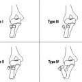
Instability in the sagittal plane is caused by hyperextension of the PIP joint or rotational longitudinal compression, often resulting in injury to the volar plate. Lesions caused by hyperextension are the lesions most frequently seen in sports practice and are sometimes associated with major articular instability. These lesions include different degrees of dorsal articular displacement, which are divided into three types according to the degree of articular instability (14–16).
In Type I lesions, hyperextension results in avulsion of the volar plate from the base of the middle phalanx or less frequently from the proximal insertion point of the check rein ligament on the proximal phalanx. Without treatment, the natural evolution of distal disruption of the volar plate from the middle phalanx is hyperextension of the PIP joint, resulting in swan neck deformity (17). Conversely, proximal disruption of the volar plate from the proximal phalanx results in pseudoboutonniére deformity, which is discussed subsequently in greater detail (18). MRI findings of volar plate injury include heterogeneous signal intensity within the normally, low-signal triangular distal attachment with contour irregularity and or thickening. Detachment with a gap is observed when an avulsion of the volar plate is present (14). Chronic lesions may demonstrate calcification or ossification within the volar plate (Fig. 18.21).
In Type II lesions, involvement of the periarticular soft tissues is more extensive with volar plate avulsion and a major split between the components of the collateral ligament complex. The joint shows a higher loss of stability than in Type I lesions, because dorsal subluxation or even dislocation of the middle phalanx may occur as a result of traction of the extensor apparatus.
The Type III lesion is characterized by a fracture–dislocation of the volar base of the middle phalanx. Several classification systems have been introduced in the literature to describe this injury. The lesion may be classified according to the size of the fragment as well as the resultant stability of the joint. A stable injury usually involves less than 40% of the articular surface and leaves the collateral ligaments attached to the middle phalanx. An unstable injury involves more than 40% of the articular surface and demonstrates compromise of the volar plate and collateral ligaments, which remain attached to the volar osseous fragment. This introduces a tendency toward dorsal subluxation (19).
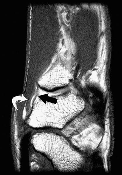
FIGURE 18.19 Superficial anterior oblique ligament and deep anterior oblique ligament of the carpometacarpal of the thumb. T1-weighted sagittal MR image after arthrography shows the deep (arrow) and superficial (curved arrow) components of the anterior oblique ligament, also known as the beak ligament.
Clinically, a volar plate injury presents as a swollen PIP joint with tenderness over the palmar aspect of the joint. The finger normally assumes a slightly flexed posture; it may be difficult to demonstrate acute hyperextension laxity as a result of pain, swelling, or guarding. This presentation may be difficult to distinguish from an injury of the flexor pulley system, specifically the A2 pulley. This distinction can be made with MRI and is important because treatment options vary for the two entities (12, 13, 17).
Pseudoboutonniére Deformity
An unusual clinical entity known as the pseudo-boutonniére deformity has been described. The condition is slowly progressive and follows injury to the PIP joint. In contrast to the true boutonniere deformity, however, the central slip is uninjured and the deformity occurs in response to rupture of the volar plate. The diagnostic features include flexion contracture of the PIP, slight hyperextension of the DIP joint that allows active flexion and is not fixed, a history of hyperextension, and radiographic evidence of calcification at the proximal attachment of the PIP volar plate. This is a condition that occurs in adults with a predilection for the ulnar digits. It stems from a partial or complete avulsion of the proximal attachment of the volar plate. The flexion deformity is caused by scarring of the volar plate with osteophyte formation during the healing process. The DIP hyperextension is the result of contracture of the lateral bands and oblique retinacular ligaments. It is important to differentiate this lesion from a true boutonniere deformity because the etiologies as well as treatments are different. In the case of pseudo-boutonniére deformity, surgery is generally reserved for cases in which the flexion contracture is greater than 40 degrees (18).
Related posts:
Stay updated, free articles. Join our Telegram channel

Full access? Get Clinical Tree


