(1)
Department of MRI, Medical Center at Siegerland Airport, Burbach, Germany
Since introduction in the early 1970s by Lauterbur, Damadian, and Mansfield, MRI has experienced a tremendous progress. A lot of “brainpower” was invested to optimize this fascinating and important imaging technique.
To understand the differences in the variety of available (Rinck 2009) systems and their effect on imaging, let us at first have a look at the functional principle of MR imaging.
The basic system architecture of a magnetic resonance imaging system is given in Fig. 2.1.
Fig. 2.1
MRI system architecture
The MRI magnet is positioned in a faraday cabin, shielding it from external influences as well as exterior areas from RF radiation.
MR imaging is a complex procedure. In the following lines, the process steps are described (Vlaardingerbroek and den Boer 2002, Stark and Bradley 1992).
1.
The user (radiologist) selects the scan sequences and defines the scan geometry data.
2.
The gradient power, as a function of time and direction, is computed by the host computer, stored, and transferred to the so-called spectrometer.
3.
The “spectrometer” comprises the control computer (controlling the magnet, the gradients, RF transmitting and receiving, RF coils, and AD converter) and is responsible for data acquisition by the receiver.
4.
Before the scan process can start, some further steps have to be performed: shimming the frequency generator on the resonance frequency (Larmor frequency), shimming the RF coils, and adjusting receiver and transmitter sensitivity.
5.
After the initialization process, the slice selection gradient is switched (usually concerning the z-axis) and the scan sequence is started. All other components of the system are deactivated at this time.
6.
After the slice selection gradient reaches its final value, the RF (radiofrequency) amplifier is activated. The input signal is given by the frequency generator, producing a harmonic signal of the frequency ω o. This signal is modulated in the function generator (amplitude modulation). The amplitude-modulated RF signal is transferred to the RF coil and the excitation pulse is emitted to the patient, producing the RF magnetic field BRF. During this time, receiver coils in the preamplifier are detuned and blocked, to provide destruction of the receiver circuits by the large RF signal.
7.
The phase-encoding gradient is switched on, until the required gradient strength is reached. Then, the 180° refocusing pulse is started. It is usually slice selective and has two times the strength of the 90° excitation pulse.
8.
Next, the readout gradient is applied. During the readout gradient time, the receiver circuit is active. The magnetization is measured, and the A/D converter is scanning the receiver signal. Following a short delay, the next element of the scan sequence is started.
9.
After completion of the scan procedure, the signal data are submitted to a Fourier transformation, and the computer image is displayed on the monitor. The user can adjust the image concerning window and level.
10.
Further image processing like 3D reconstruction, filtering, and signal intensity measurements is possible.
Besides magnetic field strength, the quality of MRI depends on several other technical features of the system: homogeneity, gradient power, send and receive coils, speed, and noise level of transmitter and receiver electronics (Rinck 2009).
In the following, the major technical components of the system are addressed.
2.1 Magnet
A constant magnetic field can be achieved by continuous electric current (electromagnets) or a permanent ferromagnetic material.
Usually, up to 0.4 T permanent magnets are used.
Resistive electromagnetic scanners have become very rare and are used in specially dedicated systems like the FONAR upright MRI or the PARAMED MR open.
Superconducting electromagnets are the current standard, mostly with a closed-bore geometry and an opening of 60 cm. Early cardiac MRI systems had smaller bores, since smaller openings lead to a considerable increase in signal.
In recent years, so-called wide-bore magnets with an opening of 70 cm have been introduced and are now widely accepted for high-field MRI scanners.
2.1.1 Permanent Magnets
Permanent magnets are produced from permanently ferromagnetic materials. The magnetic material is mounted on a C- or H-shaped carrier, made from conventional steel (Fig. 2.2). The C form gives excellent access to the patient.
Fig. 2.2
Permanent magnet with C-shaped iron ridge
They are characterized by the relation between magnetic flux and magnetic field strength. The total magnetic energy per volume unit is defined by the material.
To increase the magnetic field strength in the room between the magnetic poles by a factor of 2, the amount of magnetic material has to be increased by a factor of 4.
Increasing the linear extension of the homogeneous magnetic field (homogeneous sphere) by 1.2 requires 1.7 times more magnetic material.
The magnetic material regularly consists of a neodyne–bor–iron alloy (NdBFe) and is very expensive. Magnets produced from this material are limited to a maximum strength of 0.35 T, due to high costs and weight of the magnet.
A further requirement is to keep the magnet temperature very constant, since magnetic field strength changes occur at about 1000 ppm/K.
Permanent magnets can also be produced in a cylindrical form. This magnet type is called “prisma” magnet (Zijlstra 1985). It produces a transversal magnetic field, requiring a special RF coil design.
A major advantage of the C-shaped open permanent magnets is good accessibility to the patient during the MR procedure (Fig. 2.3).
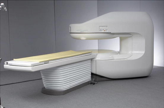
Fig. 2.3
Open low-field MRI with a permanent magnet (Hitach Aperto 0.4 T)
2.1.2 Electromagnets
Electromagnets consist of an arrangement of coils. Electric current in the magnetic core induces a magnetic field.
The magnetic flux (B o) in the coil is proportional to the number of coil windings per meter (N m) and the intensity of the electric current I (Vlaardingerbroek and den Boer 2002).
 If a magnetic coil had infinite length, the magnetic field would be perfectly homogeneous. Real coils have limited length; therefore the homogeneity is imperfect. The magnetic field of a single coil magnet is quite in homogeneous. For practical purposes, a typical example would be a four-coil magnet design, where the coil arrangement creates a field with maximal homogeneity (Vlaardingerbroek and den Boer 2002). A disadvantage of this geometry is that an exterior fringe field exists, which can interact with other measurement systems, magnetic material, data storage media, or pacemakers.
To compensate for this fringe field distortion, the magnet has to be shielded using either large amounts of iron around the coil (passive shielding) or external additional coils with electric current in the opposite direction for compensation (active shielding).
Both methods of shielding reduce the primary magnetic field strength so that a shielded magnet has to use a little more electric current than an unshielded magnet of the same magnetic strength.
So-called resistive magnets consist of two coil sets. These coils are connected with an iron ridge, increasing the efficiency (Tesla/A) by a factor of 4, compared with a system without such an iron ridge (Fig. 2.4).
Fig. 2.4
Electromagnet using an iron ridge. Instead of permanent magnets, the ridge carries two resistive magnets
A magnet with only one ridge bow is called C-arm magnet; a magnet with two bows is called H magnet.
2.1.3 Superconducting Magnets
Conventional electromagnets, using copper wire, with a field strength of more than 0.3 T, require tremendous amounts of electric power and a highly reliable electric power supply.
The solution to this problem was the development of superconducting magnets, which only need very few electricity to preserve the magnetic field.
The typical closed-bore MR magnet with horizontal field is a superconducting magnet (Fig. 2.5). It possesses six field excitation coils and two shielding coils with larger diameter to compensate for the fringe field.
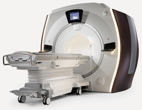
Fig. 2.5
1.5 T wide-bore superconducting magnet (GE Optima 450 w. Courtesy GE Healthcare Inc.)
The coil wire usually consists of a niob–titanium alloy with a copper mantel. This material is superconducting below a certain maximum temperature (<12 K). The temperature always has to be lower than this maximum, even at the highest electric currents.
Additionally, electric flux density and field strength have to be limited.
Without these mandatory constructional criteria, the superconductivity is lost and a critical process of heat production takes place, leading to a complete boil-off of the cooling agent (helium). This process is called “quench.” A quench process is dramatic but fortunately very rare in clinical practice.
With correct construction of the magnet system, the boil-off rate is well controlled.
To reduce heat conduction between the helium can and the surrounding air, there are two cooling shields (or vessels) for the helium compartment, in which temperature is kept at 15 or 60 K rsp, using a cryocooler.
Those three vessels are positioned in an outer vacuum container, fixed with thin wires to reduce heat conduction. Due to these thin and sensitive wires, transport of MR magnets is only possible with careful use of special transporting mobiles.
Every magnet has a specific boil-off rate, leading also to a slow reduction of the electric energy by non-Ohm effects. This means, that the resonance frequency is also reduced and the frequency generator has to be re-tuned. From time to time, the coil current has to be corrected. This is mostly combined with the helium refilling and system maintenance.
Only during the helium reloading process the magnet is connected to external energy supply.
The same type of superconducting magnets can be built with a niob–zinn conductor with a copper coverage. This material is much more expensive, but it has the advantage that the critical temperature is about 18 K. These superconducting systems do not need helium and can be run simply with a cryocooler.
Related posts:


Stay updated, free articles. Join our Telegram channel

Full access? Get Clinical Tree


