CHAPTER 2 Multidetector Computed Tomography
Computed tomography (CT) is one of the cornerstones of abdominal imaging in the United States. Rapid assessment of multiple organ systems has made CT popular among radiologists and clinicians alike. The introduction of single-detector helical computed tomography (SDCT) in 1989 was the first step in a transition from viewing CT as a series of sequential axial sections to perceiving each examination as a volumetric acquisition of anatomic data. Technical innovations in multidetector computed tomography (MDCT) have accelerated this transition. Collecting multiple channels of data with MDCT has allowed simultaneous improvements in spatial resolution and volume coverage within the finite constraints of a single breath hold or contrast bolus.
BASIC PRINCIPLES OF COMPUTED TOMOGRAPHIC TECHNIQUE
Scan Acquisition
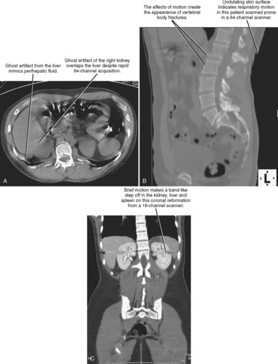
Scan acquisition is a critical step for every CT examination. Even the most sophisticated protocols performed on state-of-the-art scanners yield unsatisfactory images if the patient moves or if tube current is insufficient. Despite the rapid acquisition times of the newest scanners, breath holding is still necessary to avoid motion artifact for abdominal acquisitions. Experienced CT technologists are aware of the benefits of coaching patients through this step. The impact of poor breath-hold instructions may not be readily apparent to all technologists; therefore, if a radiologist notices frequent problems with breathing-related motion, informing the technologists may help to improve scan quality considerably. If it is unclear whether a CT abnormality is due to patient motion, multiplanar reformations (MPRs) can be useful (Fig. 2-1).
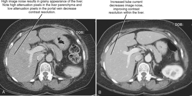
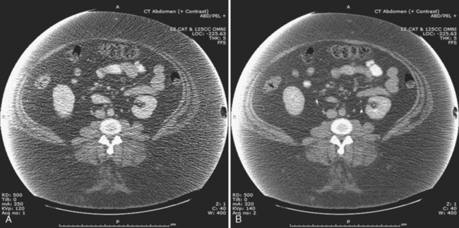
The characteristics of the radiation that passes through the patient during CT may be altered by modifying two parameters: tube current and tube potential. Tube current describes the quantity of photons emitted and is specified in milliamperes per second (mAs). Increasing tube current results in a decrease in image noise (Fig. 2-2) but also increases radiation dose to the patient in a linear fashion (a doubling of tube current results in twice as much radiation). Tube potential describes the energy of each photon emitted and is quantified in kilovolt potential (kVp). Increases in tube potential also decrease image noise and improve low-contrast resolution (ability to detect subtle differences in soft-tissue density) (Fig. 2-3). Unlike tube current, increases in tube potential result in an exponential increase in radiation dose.
Data Reconstruction
Section Thickness and Section Increment
With SDCT, section thickness is determined by beam collimation and thus cannot be altered retrospectively (as with axial CT acquisition). However, because interpolation algorithms generate axial sections at arbitrary locations along the helix, the increment (also called interval) between sections can be adjusted retrospectively with SDCT. If the increment has a smaller value than the section thickness, the sections are considered to be overlapped. Overlapping images may be used to avoid segments of “skipped” tissue that could occur with increased pitch (increasing table speed to “stretch” out the helix, covering more volume per gantry rotation). Overlapping can also be used to improve the longitudinal resolution and smoothness of multiplanar and three-dimensional (3D) images created from axial CT sections (Fig. 2-4). These interpolation algorithms become increasingly complex with MDCT because axial sections are reconstructed at arbitrary intervals along multiple helices. Because MDCT data are partitioned into small components, axial sections of variable thickness may be reconstructed for a given scan acquisition. Restrictions on reconstructed section thickness and increment on axial CT, SDCT, and MDCT are summarized in Table 2-1.
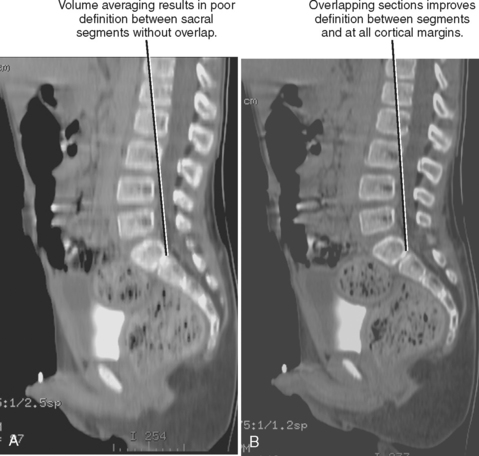
Table 2-1 Availability of Retrospective Data Reconstruction on Different Computed Tomographic Scanner Platforms
| CT Platform | Section Thickness | Increment |
|---|---|---|
| Axial CT | Fixed | Fixed |
| SDCT | Fixed | Variable |
| MDCT | Variable | Variable |
CT, Computed tomography.
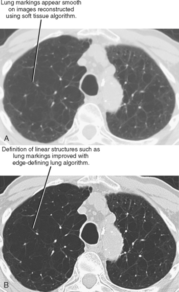
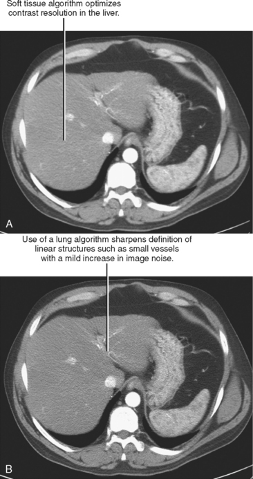
Initial or primary data reconstruction refers to the first set of axial images reconstructed from a given scan acquisition. The parameters of this reconstruction are specified on the scanner console before scan acquisition. Additional data reconstruction may be performed with a different algorithm or kernel to optimize evaluation of soft tissue, lung, or bone (Figs 2-5 and 2-6). Alternatively, data using a small section thickness and overlapping interval may be used to improve longitudinal resolution of small vessels or the margins of a mass. Data reconstruction performed subsequent to the initial reconstruction is usually called secondary data reconstruction. Most scanners now include the option to prescribe multiple sets of reconstructed sections that are generated automatically after the initial data reconstruction.
Sometimes the need for more than one set of reconstructed data is not anticipated or specified in the protocol. Additional data reconstruction prescribed after completion of the examination is referred to as retrospective data reconstruction. The ability to perform thin section data reconstruction retrospectively accounts for the versatility of newer MDCT scanners but relies on access to the projection data or “raw data” available only on the scanner. Because these data are not archived, no additional data reconstruction can be performed once it is deleted. On early MDCT scanners, the window of opportunity for data reconstruction was often only hours or a few days. As the tremendous utility of retrospective data reconstruction has become recognized (and the price of memory has decreased), vendors have been prolonging the time raw data is preserved.
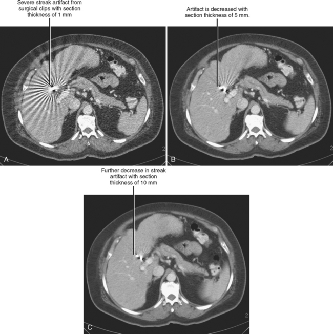
Trade-offs are to be made when selecting section thickness. Although the thin sections available with MDCT have expanded multiplanar and 3D capabilities, thin sections are not always desirable. A balance exists between spatial resolution and low-contrast resolution. Decreasing section thickness necessarily increases image noise, decreasing low-contrast resolution. It is possible to decrease thin section noise by increasing tube current, but this results in a greater radiation dose to the patient. Thin sections also worsen beam hardening and helical artifacts (Fig. 2-7).
Postprocessing
MDCT makes available thin section data that may be used to create exquisitely detailed multiplanar and 3D images. Unlike MRI, which is capable of acquiring coronal or sagittal images directly, multidimensional CT images always require the use of software to convert axial section data. In the past, most postprocessing was performed by technologists on highly specialized 3D workstations. Although this still occurs today, networked 3D systems are now available that help to integrate 3D review of CT examinations into the primary interpretation session. This is discussed in greater detail in Chapter 5.
Image Transfer
Transferring CT images to picture archiving and communication system (PACS) for viewing seems such an obvious step it might not deserve mention. However, MDCT can create examinations with hundreds or thousands of images, and transferring all of those images may not be desirable. Radiologists may choose to transfer only axial sections of traditional thickness (2-5 mm) for primary axial review to PACS, whereas channeling the entire thin-section data set separately to a 3D workstation or 3D network server. In this workflow model, postprocessed 3D and multiplanar images are eventually sent to join the original axial examination in the PACS. Others may choose to reconstruct thin-section data primarily, performing all interpretation on thin data either on PACS or with a 3D system. This limits redundancy of data, although the thin section images may appear noisy if not postprocessed.
TYPES OF MULTIDETECTOR COMPUTED TOMOGRAPHIC SCANNERS
Rapid development in CT technology has produced considerable variety among the types of MDCT scanners in use today. Not surprisingly, some of the terminology used to describe scanners can be misleading. Even the term single detector is not entirely accurate when describing SDCT. In truth, SDCT scanners typically have a single row containing hundreds of detectors exposed to a fan beam as it rotates around the patient in the axial plane. If the patient is stationary during exposure, scan acquisition is considered to be “axial.” If the patient is advancing continuously during exposure, scan acquisition is “helical.”
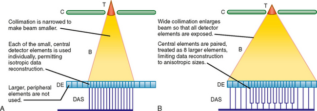
It is necessary to know the number of data channels available and the selectable values for section thickness during data reconstruction to design effective scan protocols with MDCT. Combined, these two variables are described as the “detector configuration,” as illustrated in Fig. 2-8. For example, a 16-channel scanner may be set to obtain 16 channels of data each with a section thickness of 1.25 mm or 16 channels of data each with a section thickness of 0.625 mm. In this example, available detector configurations would include 16 × 1.25 mm and 16 × 0.625 mm.
USE OF INTRAVENOUS AND ENTERIC CONTRAST MEDIA FOR MULTIDETECTOR COMPUTED TOMOGRAPHY
Intravenous Contrast Media
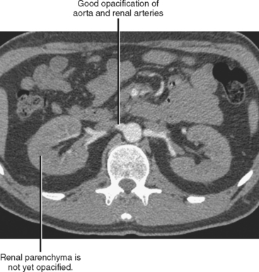
In the case of CT angiography, IV contrast media facilitate the creation of detailed 3D images of the blood vessels and improve the detection of vascular extravasation, thrombosis, and embolism. Relatively long scan times on single-channel scanners result in progression through multiple phases of vascular and parenchymal enhancement during scan acquisition. This limits the utility of single-channel scanners for vascular imaging, although it does simplify protocols. The short acquisition times of modern multichannel scanners permit imaging of discrete phases of enhancement, forcing the radiologist to make choices regarding scan delays and contrast injection profiles. For example, an examination performed early in the peak of arterial enhancement provides excellent vascular detail but little information about the veins or enhancement of solid organs (Fig. 2-9). Rapid injections of short duration are also useful for CT arteriography but may result in minimal arterial opacification during the portal venous phase (PVP). A slower rate of injection may be used to achieve some residual arterial opacification during the PVP. Because automated vessel segmentation used in most 3D workstations is more effective with uniform, dense vascular opacification, CT angiography image quality can be improved by using contrast media with a high concentration of iodine.