Fig. 6.1
The patient sits on an exam table at a comfortable height for both patient and clinician. The ultrasound machine can be on the same side of the area on the body being scanned. The examiner sits comfortably on a stool that easily moves. The clinician holds the probe in the dominant hand, using the nondominant hand to make adjustments of the machine. Alternatively the machine can be on the opposite side being scanned and an assistant can operate the machine
Selecting a Probe
Table 6.1 shows examples of the various probes and their use in MSK scanning. By far and away, the most used probe is a flat linear array probe. Its high frequency allows very high resolution scanning of tissue, but it limits the depth to only 2–3 cm. This is optimal for most structures. Deeper structures may require a low frequency curvilinear probe to be used because it is capable of greater penetration, but does not provide the high resolution of the flat probe. Because of this capability, this probe may also be best utilized in large or obese patients. Some clinicians may use a small footprint, or hockey stick probe, that allows them to manipulate around small areas such as fingers, wrists and feet. While scanning, most use their dominant hand to scan and their nondominant hand to make adjustments on the ultrasound machine. It is very important to keep the elbow to one side to prevent overuse injuries. Figure 6.2 views the proper anchoring and scanning technique that is recommended.

Table 6.1
Types of probes and their use in MSK scanning
Type | Picture | mHz | Resolution | Depth | Use |
|---|---|---|---|---|---|
Flat | 8–12 | High | 2–3 cm | Most often used | |
Curved | 3–5 | Low | Over 5 cm | Hip Large patient Deep structure | |
Small footprint | 8–12 | Very high | Very superficial | Digits Wrist Ankle Foot Procedure |
Fig. 6.2
Demonstrates proper technique to use when scanning. The probe is held with the thumb and index and ring fingers. The small and ring fingers are used to steady the probe against the skin
Scanning
Before starting to scan the patient, it is important that the proper patient identification is typed into the machine, and it is preferable that the machine is capable of recording a screenshot of the specific pathology that is noted. This screenshot must be saved especially if a procedure, such as injecting a joint or aspirating a cyst, is performed with ultrasound guidance. This may seem like a very straightforward process, but may vary from manufacturer to manufacturer. Clinicians should make themselves familiar with these features to be able to mark and copy scans. For the most part, ultrasound gel is used as the component between the probe and the skin. Some clinicians use a device called a standoff pad or immerse the digit being scanned in water to scan. These types of studies require more advanced skills and we recommend learning with the ultrasound gel. It is helpful to be generous with the gel in its application in order to facilitate better visualization.
Note that one side of the probe is usually marked with a notch or a small, raised hash mark which usually corresponds with an indicator on the left side of the ultrasound screen. Try to align the probe so that the left side of the probe correlates with the left side of the screen. This can be easily done by applying gel to the probe and simply running one’s finger along the top of the probe starting at the side of the notch, which will then correlate with the left side of the screen. This also confirms that the proper probe is connected to the machine. The following sequence should then be followed:
1.
The depth of the scan should be adjusted. The dial that controls depth should be clearly marked on the front of the scanner and the structure that is being scanned should be in the center of the screen. If the structure is on the top of the screen and there is a large amount of screen below, the depth needs to be increased. On the other hand, if the structure being scanned is on the bottom of the screen, the depth should be decreased to put the structure in the middle of the screen.
2.
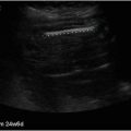
The focal zone should be adjusted. These most often can be seen as cross hashes on the side of the screen and they should be adjusted to correlate with the target. They should not be spaced throughout the whole screen, but focused on the area that needs to be scanned. Some machines have preset adjustments for each probe, so one can simply choose from various structures being scanned such as tendon or the area of the body such as the wrist.
3.
The next thing that needs to be adjusted is the brightness or the gain on the machine. Many times the first scan shows the structures that are fairly close in contrast. The gain should be adjusted to easily depict the various structures that are being scanned. When attempting to look at a structure that is usually bright or hyperechoic such as a bone, that area can be compared to a structure that is relatively hypoechoic or darker such as the muscle. The gain should then be adjusted so that the best picture and contrast can be obtained.
4.
The last thing to adjust is the doppler. There are two types of Doppler on most machines. The first is the power Doppler, which is important for evaluation of many rheumatological conditions. The power Doppler usually assesses the “power” of the blood flow to that area and roughly corresponds with microvasculature. The color Doppler, on the other hand, evaluates the direction of the blood flow, and is not as important as the power Doppler when scanning the musculoskeletal system. Table 6.2 describes the purpose and use of the various types of doppler that is superimposed on the musculoskeletal scan. This scan is often referred to as “gray scale” that we use to identify various anatomical structures. The Doppler is a box that is superimposed upon the gray scale. It is also important to note that there are many artifacts when using Doppler in MSK scanning. Random Doppler signals not correlating with anatomical structure should be ignored. To get the Doppler to the proper setting, one can scan over a bone and adjust the Doppler gain until the random artifacts cease.
Table 6.2
Doppler scan on MSK greyscale
Purpose | Use | |
|---|---|---|
Color | Direction of flow | ID blood vessels |
Power | Intensity of flow | ID inflammation, i.e., microflow or structures |
The color doppler is sometimes used to help differentiate between a vein and an artery but a much more helpful way to do this is by the use of sonopalpation, which will be described later. We discussed the gain previously, with reference to contrast or comparing one tissue to another. This is often used interchangeably with the echogenicity of the structure and it correlates to how bright something shows up on the screen. In general, a dense structure like a bone is hyperechoic; where a non-dense structure such as a collection of fluid is anechoic or black. Table 6.3.
Table 6.3
Point of care ultrasound terms describing scanned structures appearance compared to surrounding structures
Term | Reflectivity | Brightness | Example |
|---|---|---|---|
Hyperechoic | High | White | Bone |
Isoechoic | Equal | Same | Tendon |
Hypoechoic | Low | Darker | Muscle |
Anechoic
Related posts:Stay updated, free articles. Join our Telegram channel
Full access? Get Clinical Tree
 Get Clinical Tree app for offline access

|