Fig. 1.
Schematic representation of XM-2, a soft X-ray microscope for nanoimaging biological cells (located at the Advanced Light Source, Lawrence Berkeley National Laboratory, Berkeley, California). This is the first such microscope in the world to be built specifically for biological and biomedical research (for more information visit http://ncxt.lbl.gov).
1.
Brightfield Light Microscope: Zeiss Axiovert 40 CFL with Condenser 4.0 (a = 53 mm) and Zeiss Objective A-Plan 10×/0.25 Ph 1.
2.
Glass capillaries (Sutter Instrument B150-110-10).
3.
Quartz capillaries (Hilgenberg GmbH 1406785).
4.
Capillary tube puller (Sutter Instrument Co. Models P-97 & P-2000).
5.
100 nm colloidal gold nanoparticles (BB International, UK).
6.
Filters: glue (Dow Corning 732 multipurpose sealant) and 20 and 15 μm sieves (BioDesign Cellmicrosieve).
7.
Microloader tips (Eppendorf 930001007).
8.
A multi-processor computer: Apple cluster with 20 nodes, each with two dual-core processors (see Note 1 for more details).
9.
Image processing software: Matlab (Mathworks), ImageJ (National Institutes of Health, USA), XMIPP (Centro Nacional de Biotecnología, Madrid, Spain), ASPIRE (U. Michigan), and SPARX (Baylor College of Medicine) (see Note 2).
10.
3-D visualization and analysis software: Amira™ (Visage Imaging, Germany) and Avizo (VSG, France) (see Note 3).
3 Methods
3.1 Data Collection
3.1.1 Specimen Holders
When collecting imaging data for tomographic reconstruction the ideal specimen holder allows arbitrary access to a minimum of 180 ° of rotation (360 ° is even better). Use of grids and other mounting systems developed for electron microscopy hinders full rotation over angular ranges as large as these. Therefore, when possible it is preferable to use a mounting system such as thin-walled glass capillary tubes. In this chapter, we will only describe methods for imaging cells in glass or quartz capillary tubes. This approach allows full-rotation tomography, and gives optimum results. Capillary geometry allows data to be collected around a complete circle, and hence eliminates the issue of having to deal with the “missing wedge” of data inherent in other types of specimen holders. The “missing wedge” is at best a frustration that causes an unavoidable artifact in the tomographic reconstruction. At worst, this incompleteness in data makes segmentation difficult and interpretations ambiguous. Capillary specimen holders are made from glass or quartz tubes that have had one end pulled to a diameter of 2–10 μm, and have a length of more than 300 μm suitable for being imaged in the soft X-ray microscope, see Fig. 2.
Fig. 2.
Dimensions and geometry of a capillary specimen holder.
3.1.2 Adding Fiducial Markers to Capillary Specimen Holders
In order to align the images to a common frame of reference (see section below), it is beneficial to coat the capillary specimen holders with 100 nm gold fiducial markers, prior to loading them with cells. This can be done easily using commercially available gold nanoparticles.
1.
To coat the capillary specimen holder, simply dip it in the solution of 100 nm gold nanoparticles and slowly withdraw.
2.
While the outside of tube is being coated, gently blow air through the capillary to prevent the solution from getting inside.
3.1.3 Specimen Preparation
Prior to being imaged using SXT, lower order cells do not require any special preparation. Indeed, cells such as prokaryotes or yeast can simply be taken from their growth chamber and pipetted directly into a specimen holder and then mounted in the soft X-ray microscope. In some cases the growth media is very high in carbon and nitrogen, and it may be advantageous to transfer the cells into phosphate-buffered saline solution; however, this is not a prerequisite.
For higher order mammalian cells, particularly adherent cells, more care must be taken to ensure the good health of the cells when they are imaged. In general, we have found the following protocol to produce the best results when imaging adherent cells.
3.1.4 Thawing Adherent Cells to Plating
1.
Remove a mammalian cell stock vial from liquid nitrogen temperature storage. If the vial has been submerged in nitrogen, assume nitrogen has seeped into the vial and do not allow it to warm in your hands. Touch the vial as little as possible and always point the cap away from you and others. Place the vial in a preheated 37°C water bath and allow it to thaw for 2–2.5 min. Do not allow the cells to stay at 37°C once the vial is thawed. At nonfreezing temperatures, DMSO, glycerol, etc., can be detrimental to the structural integrity of the cell; this is especially obvious in terms of the cell’s surface.
2.
The outside of the thawed vial is sterilized by dunking, spraying, or dripping with 70% ethanol in water. Open the vial under sterile conditions and transfer the contents to preheated 37°C media. Freshly frozen cells can be fragile so transfer cells slowly into and out of serological pipette and use care to avoid introducing bubbles.
3.
Cell number/cm2 differs depending on the size of the cell and the particular requirement of cell line but, generally, plate cells at ∼15% density in a plastic cell culture plate, dish or flask. Some cell lines may require a surface coating such as fibronectin, laminin, etc.; however, the actual plating density and surface of growth is cell line specific, and must be determined on a case-by-case basis.
3.1.5 Suspending Adherent Mammalian Cells
Prior to being imaged, adherent mammalian cells are suspended in solution. Once suspended, adherent mammalian cells are treated identically to prokaryotes or lower order eukaryotes, such as yeasts.
1.
Filter trypsin, media, and soybean trypsin inhibitor using a 0.2 μm filter to remove debris or other particulate matter.
2.
Use trypsin to detach adherent cells for loading into a sample holder (see Note 4). In our hands, we see the best results when cells are detached from plates that are 75–80% confluent.
3.
Generally, for a 75 cm2 flask, aspirate media, then quickly wash serum from the cell layer with 3 mL of 0.25% trypsin and aspirate wash. Add back 1 mL 0.25% trypsin, distribute, and incubate at 37°C for 2 min or until cells move when the plate is tilted.
4.
Stop trypsin by adding 10 mL of media containing 10% serum.
5.
Pellet cells by centrifugation (0.3 rcf for 4–10 min) and resuspend the pellet in 400 μL to 1 mL of media.
3.1.6 Specimen Loading in Capillary Sample Holders
Cells must be loaded into the narrow, drawn region of the specimen holder and debris must be kept to a minimum. To help achieve selection of single cells and to minimize debris, size selection via fluorescence-activated cell sorting (FACS) or filtration is recommended. Filtration by size is described below; discussing FACS of cells is out of the scope of this chapter and may be a protocol that needs to be carried out at a specialist resource, depending on availability.
1.
Using a clean air source, blow air into filters and Eppendorf tubes to remove debris, and filter all liquids using a 0.2 μm filter.
2.
Construct filter set-ups by gluing 1.5 cm2 squares of BioDesign Cellmicrosieve (20 and 15 μm) onto halved p1000 pipetman tips that have been cut in half to remove the pointed tips. Fit the filter set-ups into 1.5 mL Eppendorf tubes and transfer suspended cells onto filters. Selection for size is done by centrifugation (0.2 rcf for 10 s) using first 20 μm, then 15 μm filters.
3.
After final filtration, remove filter set-ups from Eppendorf tubes and pellet cells (0.3 rcf for 4 min). For efficient loading, a high cell titer is recommended. Resuspend the pellet into a volume of loading media (usually growth media) that is 1× to 2× volume of the pellet.
4.
To load cells into a glass capillary tube, add 0.98 μL of high titer cell solution into a microloader tip. Thread the microloader tip into the back end of a capillary tube, place the tip of the microloader in the region of the capillary tube where the glass begins to taper into the portion that has been pulled to a diameter of between 2 and 10 μm and dispense fluid. About 0.1 μL of fluid will fill the pulled tip.
5.
Under a brightfield light microscope (10× or higher magnification air lens), check that cells are in the region of the glass capillary tube where the sample holder has narrowed to 15 μm or less in diameter. Remove any moveable fluid from the sample holder.
6.
Capillary sample holders with cells spanning a 2–10 mm region along its length are ready to be rapidly frozen at the beamline or plunge frozen for later imaging.
3.1.7 Cryofixation
There is a significant amount of literature from the electron microscopy community on cryofixation (20–23). Because SXT imaging is carried out with lower spatial resolution than electron tomography (i.e., 50 nm rather than a few nm), and with X-rays rather than electrons, not all of the commonly accepted “rules” for cryofixation developed by electron microscopists apply (see Note 5). In practice, for soft X-ray tomography success has been achieved with each of two different approaches to cryofixation: cryogenic gas streams and plunge freezing.
1.
First, set up a cryostage in the soft X-ray tomography instrument to maintain the sample at near liquid nitrogen temperature with a stream of cryogenic helium gas at atmospheric pressure (this is the set up of the XM-2 instrument at the ALS in Berkeley).
2.
First approach to freezing: Cryogenic gas stream. Mount the sample on the sample stage so that it is outside of the cryogenically cooled region, and then quickly plunge the sample into the cryogenically cooled stream of cold helium gas. The sample is then maintained in the stream of helium gas for the duration of the experiment.
3.
Second approach to freezing: Plunge freezing. Quickly plunge the sample into cryogenic liquid such as liquid propane, liquid ethane, or any other suitable media. In principle, this approach can be straightforward, to the extent that the capillary can be simply plunged manually into the cryogenic liquid. However, to maintain consistency, and allow the speed of plunging to be controlled, it is better if this process is carried out using instrumentation that can vary the speed with which the capillary enters the liquid. Moreover, the plunging time is specimen dependent. For some specimens the time taken to plunge into cryogen is unimportant, for others it is essential that the specimen is plunged as quickly as possible. One difficulty with this technique is maintaining the specimen at cryogenic temperature whilst it is being transferred from the cryogenic liquid onto the sample cryostage of the X-ray microscope; this requires the use of a cryotransfer device. In practice, this can be challenging, and is an additional potential cause of damage to the specimen, if the transfer device is inadvertently allowed to warm up during use. The development of new plunge methods and instruments is very much a work in progress.
In either of these approaches, the final result of the procedure is that the specimen has been loaded into a cryogenically cooled helium gas stream, and is held in place by a spring-loaded clip attached to a motion control stage. At this point, data collection can begin.
3.2 Soft X-Ray Microscopic Data Collection
In the following sections we will describe data collection using the soft X-ray microscope XM-2 located at the Advanced Light Source (ALS), Berkeley. However, the basic principles and concepts will apply to data collection using any soft X-ray microscope.
3.2.1 Aligning the Specimen in the Microscope
The previous section described the process of mounting the specimen in a capillary holder, and cryocooling the sample, typically in situ in the XM-2 cryorotation stage. When the sample is being cooled using the gas method (most common for cells less than 5 μm in diameter), an alignment step is performed after the sample is mounted but before it is cooled. Using the plunge freezing method, the capillary is aligned off-line prior to mounting. Alignment places the tip of the capillary such that the region to be imaged is centered on the axis of rotation. This is an important step. During tomographic data collection the specimen is rotated by 180 °; during which the specimen should not leave the field of view. The specimen will stay in the field of view during this rotation only if it is centered on the axis of rotation.
1.
To perform this alignment, the sample is positioned at 0 and 180 °, and the position of the tube is recorded. A tip-tilt stage controlled by a joystick is used to adjust the capillary such that it splits the difference between its positions at the two angles. This procedure is repeated for the tube when positioned at 90 and 270 °. Typically, two rounds of alignment are performed to confirm that the tube is exactly centered, especially in the case of large tubes (greater than 8 μm) that nearly fill the field of view.
2.
The capillary is then lowered quickly into the cryogenic gas stream.
3.
Once the tube is aligned and lowered into position for X-ray imaging, the tip-tilt alignment procedure is repeated a final time at finer resolution using X-ray imaging, usually using a region above or below the sample of interest to reduce the X-ray dose on the sample to be imaged.
3.2.2 Tomographic Data Collection
1.
Look for fields of view that contain cells of interest for the given experiment. Projection images are taken along the length of the capillary. This allows the position of the optimal fields of view to be identified.
2.
Set up a tomography scan. In the XM-2 control GUI, sample description is saved in a header file along with the image data; this information is also transferred into the image database. The parameters for the scan are also selected: exposure time, angular increment and total angular range. Exposure time is chosen such that the CCD receives the maximum number of counts without saturating (also known as clipping) any pixels, generally around 100 ms on this microscope. The angular increment is generally between 1 and 2 °, for a total number of images between 90 and 180, spread over 180 °.
3.
After the scan is started, continue observing the sample. In rare cases, drift leads the specimen to leave the field of view during the scan. In this case, slightly adjust the horizontal or vertical position between images to re-center the sample in the field of view. Obviously, this adjustment should be timed so that it is not carried out during acquisition of an image.
4.
Collect a set of “flatfield” images before and after tomographic image data are recorded. To do this, move the capillary out of the field of view, and collect a series of 10–20 images. By combining these images with the sample images from the tomogram, the percent transmission can be calculated, yielding quantitative X-ray absorption data.
5.
Data for a completed tomographic set is saved as 16 bit unsigned tiff stacks. There are a total of three files: one with the initial flat fields, one tomography image series, and one with the final flat fields.
3.3 Data Processing
3.3.1 Image Correction and Normalization
1.
As the first step in processing the images, subtract the detector dark counts from both the sample images and the flat field images. The dark counts can be measured by collecting an image with the X-ray shutter closed. The dark field image only needs to be measured every few months; our experience is that it does not change on this time scale.
2.
 Introduction: Nanoimaging Techniques in Biology
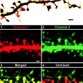 Two-Color STED Imaging of Synapses in Living Brain Slices
 Secondary Ion Mass Spectrometry Imaging of Biological Membranes at High Spatial Resolution
 High Data Output Method for 3-D Correlative Light-Electron Microscopy Using Ultrathin Cryosections
 Functional AFM Imaging of Cellular Membranes Using Functionalized Tips
 Single-Molecule Tracking of mRNA in Living Cells


After subtracting the dark counts, average each of the two sets of flat field images to produce a single initial flat field image and a single final flat field image. Average multiple flat fields to reduce the noise level.
Related posts:
Introduction: Nanoimaging Techniques in Biology
Two-Color STED Imaging of Synapses in Living Brain Slices
Secondary Ion Mass Spectrometry Imaging of Biological Membranes at High Spatial Resolution
High Data Output Method for 3-D Correlative Light-Electron Microscopy Using Ultrathin Cryosections
Functional AFM Imaging of Cellular Membranes Using Functionalized Tips
Single-Molecule Tracking of mRNA in Living Cells
Stay updated, free articles. Join our Telegram channel
Full access? Get Clinical Tree
