Fig. 1.
A magnified view of a typical aluminum-coated NSOM probe fabricated using the heating and pulling method. A small spot of light can be seen emerging from the distal end of the probe. The probe has been fabricated with a double taper geometry which, for general NSOM imaging, strikes a balance between light throughput and small aperture size.
While electron microscopy has been extraordinarily successful at directly probing biological structures, the increased spatial resolution comes at the expense of working conditions, optical contrast mechanisms, and often very high costs. Fluorescence microscopy, on the other hand, is comparatively inexpensive and easily implemented on fixed or viable biological tissues. It also has an extensive history of fluorescent probe and method development, and exhibits spectroscopic, polarization, and dynamic capabilities. These attributes prove especially powerful for biological studies and it is these applications that have driven many of the technological developments experienced in fluorescence microscopy. A major goal in developing NSOM, therefore, was to create a fluorescence method that retains the favorable attributes associated with conventional fluorescence microscopy but with a spatial resolution approaching that attainable with electron microscopy.
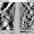
Figure 2 shows a NSOM fluorescence image which demonstrates the sub-diffraction-limited spatial resolution possible with this technique. Each bright spot in Fig. 2 represents fluorescence from a single dye molecule dispersed in a lipid monolayer. Since the individual dye molecules are much smaller than the NSOM aperture, the feature size reflects the aperture diameter of the particular NSOM probe used for imaging (see Note 1). Each single molecule emission feature in Fig. 2 has a full-width half-maximum of ∼20–30 nm, illustrating the high spatial resolution capabilities of NSOM (7). This example, therefore, demonstrates both the single molecule fluorescence detection limits of NSOM and its high spatial resolution, which is an order of magnitude better than that obtained with conventional optical approaches (1, 7, 10, 11). Moreover, since a feedback mechanism is implemented to maintain the tip–sample gap during scanning, NSOM provides a force mapping of surface topography much like atomic force microscopy (AFM). For biological applications and especially those involving membranes, the simultaneously measured NSOM fluorescence and topography images provides unique capabilities for directly comparing the location of optical markers with sample structure. These attributes offer intriguing possibilities for studying nanometric biological structures such as lipid rafts in membranes.
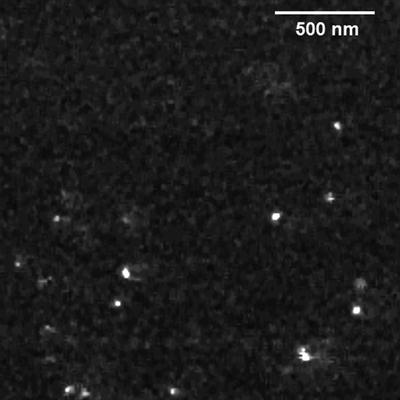
Fig. 2.
NSOM fluorescence image of a 2 μm × 2 μm region of a DPPC monolayer doped with the fluorescent lipid marker DiIC18. Each emission feature represents fluorescence from a single probe molecule in the membrane and has a FWHM of ∼20–30 nm. This illustrates the high spatial resolution and single molecule detection limits of NSOM. Because the reporter molecule is much smaller than the NSOM probe, the FWHM of each emission feature reflects the size of the particular NSOM aperture used in the imaging.
While commercial instrumentation is marketed for NSOM measurements, it is straightforward to modify existing scanning probe microscopes to implement NSOM. Here we discuss in detail how our particular NSOM instrumentation is constructed and the methods that we have learned for optimizing NSOM performance. Before outlining the details of this approach, however, we discuss how NSOM probes are fabricated. Resolution is largely dictated by the quality of the NSOM probe and, in our view, it is very important that the NSOM tips be fabricated in-house. We, therefore, provide a short primer on the fiber optic probe fabrication and metal coating conditions that we have found consistently lead to NSOM probes with well-defined, small apertures.
2 Materials
There are many ways of incorporating NSOM capabilities onto existing AFM platforms. Listed below are the major pieces of instrumentation used in our laboratory for this along with that needed for NSOM tip fabrication.
1.
Digital Instruments Nanoscope IIIa AFM controller and work station (Now Bruker, http://www.bruker-axs.com): Bioscope backplane electronics module, signal access module, photon counting module.
2.
Zeiss Axiovert 100 inverted fluorescence microscope equipped with high numerical aperture objective (FLUAR, 60×/1.45 oil) or equivalent.
3.
X–Y closed-loop piezo sample scanner with central void to accommodate microscope objective (Mad City Labs, Nano H100, http://www.madcitylabs.com).
4.
Avalanche photodiode (APD) single photon counting module (EG&G SPCM-AQR).
6.
Long working distance microscope (Infinity K2, http://infinity-usa.com) with CCD camera (Cohu, http://www.cohu.com/) or equivalent to monitor tip position above the sample.
7.
Lock-in amplifier for detecting the shear-force feedback signal (Stanford Research Systems, SR830 DSP lock-in amplifier, http://www.thinksrs.com).
8.
Sutter Instruments P-2000 micropipette puller or equivalent with arms modified to accept single-mode optical fiber (www.sutter.com).
10.
Thermal evaporation chamber with deposition monitor for coating aluminum onto probes.
3 Methods
3.1 Tip Fabrication
As with all scanning probe techniques, the quality of the measurement is largely dictated by the quality of the probe. This seems to be especially true for NSOM where the formation of a sub-wavelength aperture for the delivery of light can be problematic. There are two main approaches for fabricating tapers in the fiber optics used for NSOM tips: one is through chemical etching while the other utilizes a heating and pulling method (12, 13). Each technique offers distinct advantages and disadvantages. The chemical etching approach uses chemical etchants, such as hydrofluoric acid, to form tapers in the fiber optic probes. The main advantage of this technique is that very large taper angles can be fabricated which increases light throughput efficiency (13–17). This approach is also inexpensive and easily scaled for simultaneous probe production. However, even with the newer tube etching approaches, this technique often produces probes with rough, pitted, or jagged surfaces which degrade the quality of the metal coating used to confine light within the aperture. Since the quality of the metal coating is the key metric for NSOM tip performance, this is a major obstacle for the chemical etching approach. For this reason, we find that the heating and pulling method for tip formation remains the best approach for standard NSOM tip fabrication (18, 19). This is the most prevalent approach for fabricating NSOM probes and, in our experience, the easiest method for reproducibly fabricating probes once the proper procedures are in place. We will, therefore, limit our discussion to fiber optic probes heated and pulled to a taper and then coated with aluminum.
3.1.1 Heating and Pulling Fiber Optic Probes
The heating and pulling method utilizes a heat source to soften the fiber and a pulling mechanism to draw the fiber down to the point of rupture. This approach is simple and once the appropriate parameters are found, it is very repeatable. While the method does require additional instrumentation, it yields very reproducible tapers with exquisitely smooth and clean surfaces that enable deposition of high-quality metal films (see Note 2).
1.
To fabricate NSOM probes we use single mode optical fiber with 125 μm cladding. We have used single mode fiber from a number of vendors and find no difference for probe fabrication.
2.
Approximately 5 mm of the jacket is removed with fiber strippers and the exposed fiber optic cleaned with ethanol. The fiber is mounted in a Sutter Instruments P-2000 micropipette puller with arms modified to accept single-mode optical fiber. These pullers incorporate a CO2 laser for the heat source and programmable control over all important parameters for taper formation such as laser power, pull strength, and pull delay. These parameters enable a large range of taper shapes to be fabricated in fiber optic probes. For example, high heat and hard pulls result in long tapers with very small tip apertures while low heat and soft pulls result in short tapers with larger tip apertures (18, 19). Unfortunately, this approach cannot create short tapers with small apertures, a combination that incorporates efficient light throughput with high spatial resolution. Etching methods can produce this geometry, but as mentioned earlier have other issues that make metal coating difficult. We have explored both approaches in our laboratory and believe the heating and pulling method produces quality probes with small apertures more reliably.
3.
The exposed fiber is aligned in the path of the heating laser and clamped in place. The fiber is then heated and pulled using parameters that lead to the desired tip shape (see Note 3). It is important that the laser and fiber be aligned properly to obtain a symmetric taper. This should be checked from time to time by positioning a piece of thermal fax paper behind the fiber while momentarily firing the laser on low power. The laser spot burned on the fax paper should have a shadow from the fiber exactly bisecting the spot. If the line is high or low on the spot, asymmetric tapers can result.
4.
To ensure tip to tip consistency, we only use pulled fibers from one arm of the puller and discard the other. The pulled fibers are immediately stored in an enclosed container to reduce dust contamination until loaded into the coating chamber.
3.1.2 Aluminum-Coated NSOM Probes
Tapered fiber optic probes alone are not sufficient to act as NSOM probes since light escapes from the sides of the taper region. A reflective coating must be deposited on the taper to confine light within the probe until exiting a well-defined aperture at the distal end of the probe (3, 18). Without the reflective film, escaping light can excite fluorescence in the sample which leads to complicated patterns in the fluorescence image (9).
1.
To confine light within the taper until exiting a well-defined aperture at the probe end, a reflective film of 50–100 nm of aluminum is coated around the sides. Aluminum has superior reflectivity properties in the visible region of the spectrum and, thus, requires the least amount of material to confine excitation light (20). This is important as the overall dimensions of the NSOM probe affects how close the probe aperture can approach the sample surface. While aluminum has the best optical properties, it unfortunately has a propensity to form oxides during the coating process (21). The oxides tend to dramatically degrade both the reflective properties of the coated film and the resulting performance metrics of the NSOM tip (22–25). In our opinion, the metal-coating step in fabricating NSOM probes represents the largest single barrier that must be overcome before carrying out quality NSOM measurements. Fortunately, much is known about coating aluminum and with care, high-quality, thin reflective Al films can be easily deposited onto tapered fiber optics.
2.
To reduce oxide formation during film deposition, the coating needs to be carried out under a good vacuum. Achieving vacuum quickly is also important to reduce the batch time required for tip fabrication. We use a custom built thermal evaporation chamber (see Fig. 3) that uses a turbo pump to achieve pressures of 10−6 Torr in a few hours (see Note 4). Turbo pumps are desirable over diffusion pumps since they are cleaner and capable of achieving vacuum quickly.
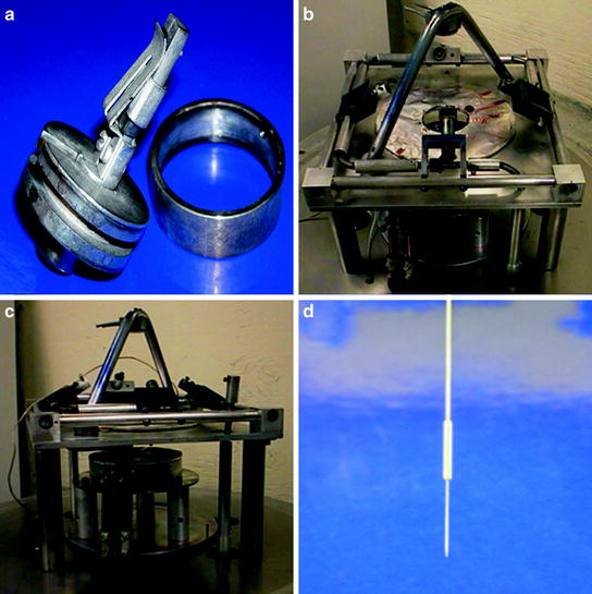
Fig. 3.
(a) A fiber-chuck is used to hold the NSOM probe in the evaporative coater. The extra length of fiber from the NSOM probe is sealed inside the spin-chuck with a removable metal ring. (b) Four rotating mounts position the fiber chucks above a central opening, housing the thermal aluminum evaporation element. Mounted above the rotating tips is a quartz crystal microbalance to measure deposition rate and total film thickness. (c) The aluminum evaporation element is surrounded by a metal housing to reduce heating experienced at the tips. A manual shutter is used to block the source when melting and degassing the Al before coating the tips. (d) A metal jacket is glued to an aluminum-coated NSOM probe to assist in mounting the tip in the NSOM head.
3.
The pulled fibers are mounted in a custom-built spinning mechanism that rotates the probes while coating to evenly deposit the metal film around the taper. The fiber is mounted into the fiber chuck shown in Fig. 3a. The all metal chuck is vacuum compatible and contains a spring clamp that immobilizes the fiber and a spool where the excess fiber is wound within and covered with the ring shown. Approximately 1 cm of the tapered probe extends from the top of the chuck for coating.
4.
As shown in Figs. 3b, c, four fiber chucks can be mounted in the rotating platform. The rotating mounts spin the tips during coating to evenly expose the sides of the taper. The coating must be deposited such that only the sides of the taper are coated, leaving the aperture at the end of the tip free for light to exit. Given these constraints, thermal evaporative coating methods tend to work the best. Thermal evaporation can achieve very high deposition rates and since the deposition is line of sight, simply orienting the tips away from the aluminum source leaves the aperture uncoated. The tips, therefore, are tilted away from the aluminum source at an angle of approximately 35 °. The fiber probes are held 20 cm from the aluminum source and a rotating feedthrough is used to spin the tips at a rate of approximately 5 Hz during deposition.
5.
In-house fabricated tantalum boats are used to hold and heat the aluminum. We have tried various materials and geometries for holding and heating the aluminum and found tantalum works the best for us. Tantalum is malleable so boat fabrication is simple and it is able to handle the large currents necessary for fast evaporation rates without boat failure. The boats should be as small as possible to reduce chamber heating, which can also have deleterious effects on the Al coating quality. In our configuration, we use boats with dimensions ∼1 × 5 cm cut from a 0.015 in.-thick tantalum sheet. Fresh boats are used for each coating and loaded with approximately 5 in. of 1.0 mm-diameter aluminum wire (99.999%, Aldrich).
6.
It is essential that the chamber incorporate a shutter above the aluminum source. For quality films, the aluminum needs to be melted, degassed, and impurities burned-off before opening the shutter and exposing the tips to the aluminum. The aluminum should be heated sufficiently so that once the shutter is opened, a high deposition rate is immediately achieved.
7.
We have found that enclosing the heating apparatus (electrodes, tantalum boat, and aluminum) in a metal housing helps reduce ambient heating and leads to smoother aluminum films on the probes.
8.
Pinholes in the aluminum coating often indicate the presence of contamination on the pulled fiber (20). It is important to decrease the time between pulling the fiber and getting it into vacuum to reduce the chances of dust attaching to the surface.
9.
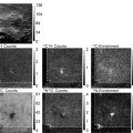
As mentioned, several parameters are important for obtaining smooth, highly reflective aluminum coatings on NSOM probes. Obviously, obtaining a good vacuum is important since this will reduce the presence of oxygen which is known to degrade coating quality by forming aluminum oxide grains. As an example, Figs. 4a, b compare AFM topography images of NSOM probes coated at 1 × 10⁻³ Torr and 3 × 10⁻⁶ Torr, both coated at the same deposition rate. The 2 μm × 2 μm images reveal a dramatic reduction in grain size as the ambient pressure is reduced. Similarly, deposition rate is found to significantly affect the final grain structure in the aluminum coating. Figure 4c, d compares AFM measurements from NSOM tips coated at low and high deposition rates. Clearly, higher rates correspond to smaller grains and smoother coatings which translate into higher film reflectivity (20, 26). These results are summarized in Table 1 which tabulates the mean surface roughness of the aluminum coating under various conditions.
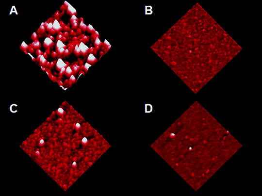
Fig. 4.
2 μm × 2 μm AFM images of the aluminum coatings applied to NSOM probes in vacuums of (a) 1 × 10⁻³ Torr and (b) 3 × 10⁻⁶ Torr. As seen in these images, a decrease in the chamber pressure results in a considerable decrease in roughness of the Al coating. Figures (c) and (d) show similar AFM measurements on NSOM tip coatings deposited at rates of 30 Å/s and 2,000 Å/s, respectively. These results show that the quality of the Al coating also depends on the rate of deposition, with faster rates preferable over slow depositions. Adapted from ref. 20 with permission.
Table 1
Mean surface roughness of Al coatings of NSOM probes deposited under various conditions as measured by AFM
Coating condition | Surface roughness mean (Std. Dev.) (nm) |
|---|---|
Pressure = 1 × 10⁻³ Torr | 68.1(24.9) |
Pressure = 1 × 10⁻⁴ Torr | 34.6(2.7) |
Pressure = 1 × 10⁻⁵ Torr | 20.7(2.6) |
Pressure = 3 × 10⁻⁶ Torr | 16.1(2.2) |
Rate = 30 Å/s | 36.3(7.6) |
Rate = 700 Å/s | 18.3(2.0) |
Rate = 2,000 Å/s | 10.5(2.0) |
10.
 Introduction: Nanoimaging Techniques in Biology
 Two-Color STED Imaging of Synapses in Living Brain Slices
 Secondary Ion Mass Spectrometry Imaging of Biological Membranes at High Spatial Resolution
 High Data Output Method for 3-D Correlative Light-Electron Microscopy Using Ultrathin Cryosections
 Functional AFM Imaging of Cellular Membranes Using Functionalized Tips
 Single-Molecule Tracking of mRNA in Living Cells


Once coated with 50–100 nm of aluminum, a metal collar is glued onto the end of the NSOM probe as shown in Fig. 3d. The collar enables the probe to be firmly held in the NSOM head without damage. Since the tip will be oscillated for feedback, it is important that the collar be glued firmly on the probe so the dithering amplitude gets transferred efficiently to the probe.
Related posts:
Introduction: Nanoimaging Techniques in Biology
Two-Color STED Imaging of Synapses in Living Brain Slices
Secondary Ion Mass Spectrometry Imaging of Biological Membranes at High Spatial Resolution
High Data Output Method for 3-D Correlative Light-Electron Microscopy Using Ultrathin Cryosections
Functional AFM Imaging of Cellular Membranes Using Functionalized Tips
Single-Molecule Tracking of mRNA in Living Cells
Stay updated, free articles. Join our Telegram channel
Full access? Get Clinical Tree
