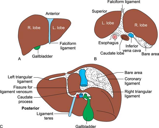
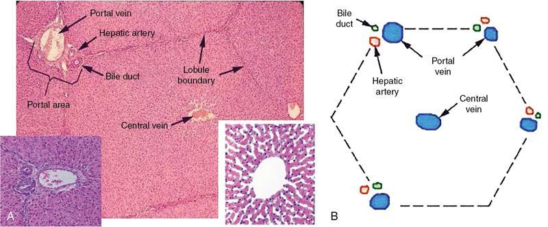
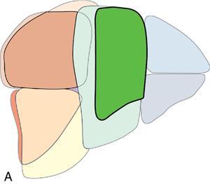
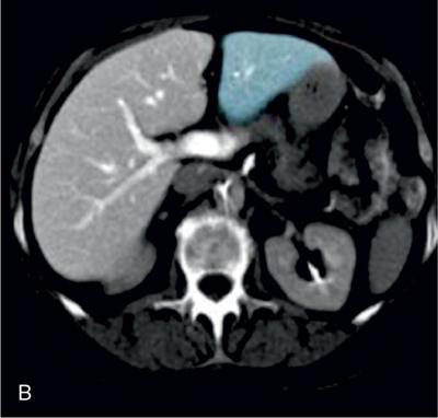
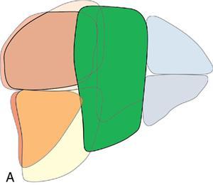
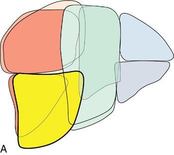
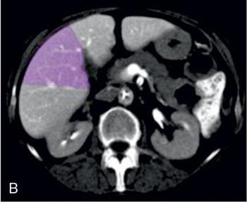
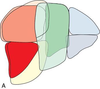
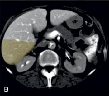
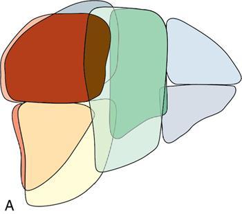
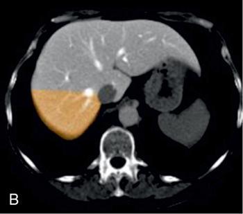
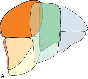
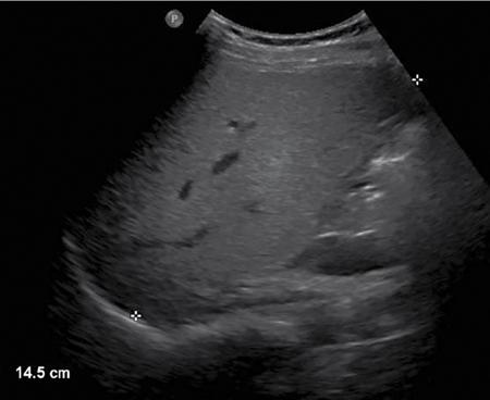
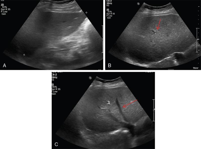
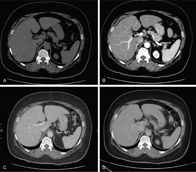
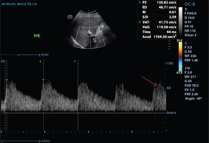
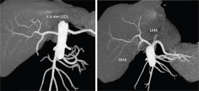
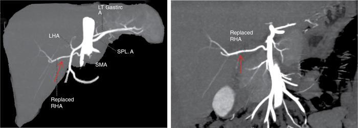
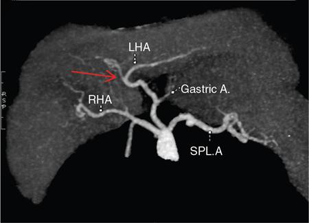
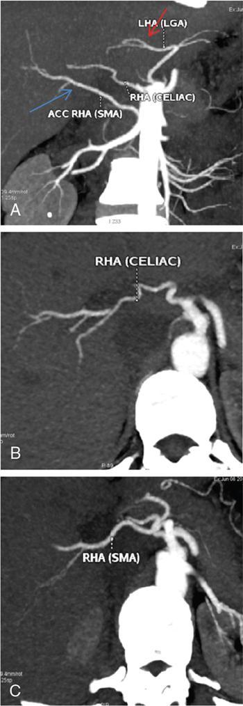
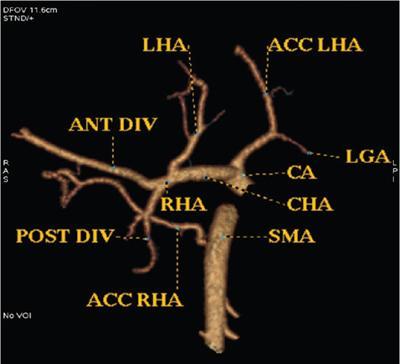
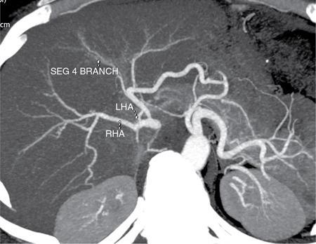
Ritu K. Kashikar, Shrinivas B. Desai Imaging is the mainstay of noninvasive diagnosis of the spectrum of abdominal pathologies or proving absence off thereof. Knowledge of normal anatomy and important normal variants is thus essential for the radiologist in order to avoid misinterpretation or erroneous diagnosis. This chapter highlights the normal anatomy of the hepatobiliary systems including the blood vessel and draining ducts and discusses relevant anatomical variants which may have important clinic implications. The liver is the largest abdominal organ, occupying the right upper abdominal quadrant and is in close approximation with the diaphragm, stomach and the gallbladder. It is largely covered by the costal cartilages. The liver is encapsulated by Glisson’s capsule which is a dense layer of connective tissue. It is covered by peritoneum, except in the regions of gallbladder fossa, fossa for inferior vena cava (IVC), and the bare area. The bare area is the posterocranial aspect of the liver, adjacent to the dorsal body wall, which is not covered by peritoneum. The liver has two surfaces, the convex diaphragmatic surface and a concave visceral surface. The slit in the hepatic hilum is called the porta hepatis and is penetrated by the right and left hepatic ducts (LHDs), hepatic artery and portal vein (PV). The distal portion of the lesser omentum is called the hepatoduodenal ligament and contains the common bile duct (CBD), hepatic artery, PV, nerves of liver and lymphatics. The liver has dual blood supply with hepatic artery providing 25% of hepatic blood and rest by portal vein (Fig. 9.2.1). Five ligaments connect the liver to the undersurface of the diaphragm. These include the falciform, the coronary and two lateral ligaments, all of which are peritoneal folds. The fifth ligament is a fibrous cord-like structure and represents the obliterated umbilical vein. The peritoneum invaginates into the liver parenchyma leading to formation of fissures. There are four normal fissures: fissures for the ligamentum teres, ligamentum venosum and gallbladder and the transverse fissure (Fig. 9.2.2). The liver is organized into microscopic functional units called lobules or acini. A central terminal hepatic venule surrounded by four to six terminal portal triads form a polygonal unit called the hepatic lobule. The terminal portal triad branches line the periphery of the unit. Between the terminal portal triads and the central hepatic venule the hepatocytes are arranged in one cell thick plates, surrounded by sinusoids. The blood flows from the terminal portal triad through sinusoids into terminal hepatic venule. Bile formed within the hepatocytes empties into terminal canaliculi which coalesce into the bile ducts (Fig. 9.2.3). This structure of the functional hepatic unit forms the basis of various functions of the liver. The normal relations of the liver are: The liver can be divided into right, left and caudate lobes. The right and left lobes are separated by the interlobular fissure and is oriented along a line passing through the gallbladder fossa inferiorly and the middle hepatic vein (MHV) superiorly (Fig. 9.2.4). This plane runs from the left of the IVC to the left of the gallbladder fossa and is a called the Cantlie’s line. Use of standardized, segmental anatomy is imperative because it facilitates communication and treatment planning. The segmental anatomy of liver is primarily based on vascular anatomy. The right lobe is divided into anterior and posterior sectors by of the right hepatic vein (RHV). The left lobe is divided into medial and lateraI sectors by an oblique plane connecting the left hepatic vein (LHV) and the falciform ligament. The liver is divided into upper and lower segments at the level of main portal vein (MPV) bifurcation (Fig. 9.2.5). Various systems are used in classification of liver anatomy. These are discussed in Table 9.2.1. The Couinaud’s system is the most commonly used and divides eight sections/segments which are discussed in details below (Table 9.2.2). 1. Segment 1 – Caudate lobe Bounded anteriorly and medially by the fissure for ligamentum venosum (Fig. 9.2.6). 2. Segment 2: Superior segment of the left lateral sector/section Bounded medially by falciform ligament and inferiorly by plane of MPV, also known as the posterior lateral sector (Bismuth, FCAT) (Fig. 9.2.7). 3. Segment 3: Inferior segment of left lateral sector/section Bounded medially by the falciform ligament and superiorly by the plane of the MPV bifurcation, also referred to as lateral anterior sector (Bismuth, FCAT) (Fig. 9.2.8). 4. Segment 4: Left medial sector/section Bounded laterally by falciform ligament and medially by Cantlie’s line (Fig. 9.2.9). 5. Segment 5: Inferior segment of the right anterior sector/section Bounded anteriorly by the gallbladder fossa and posteriorly by the plane of the RHV, superiorly bounded by the plane of MPV bifurcation (Fig. 9.2.10). 6. Segment 6: Inferior segment of the right posterior sector/section Bounded anteriorly by plane of the RHP and superiorly by the plane of the MPV bifurcation (Fig. 9.2.11). 7. Segment 7: Superior segment of the right posterior sector/section Bounded anteriorly by the plane of the RHV and inferiorly by the plane of the MPV bifurcation (Fig. 9.2.12). 8. Segment 8: Superior segment of the right anterior sector/section Bounded anteriorly by the plane of the gallbladder fossa and MHV, posteriorly bounded by the plane of the RHV and inferiorly by the plane of the MPV bifurcation (Fig. 9.2.13). Owing to its broad area of contact with the anterior abdominal wall, the liver is an ideal organ for evaluation with sonography. Ultrasound is commonly used for evaluation of size of the liver. On longitudinal scans obtained through the midhepatic line, if the liver measures 13 cm or less, it is normal in 93% of individuals (Fig. 9.2.14). The size of liver in various planes is discussed in chapter on normograms. When the area of contact between the liver and the anterior border of the right kidney, exceeds below two thirds of the kidney, the liver is considered as enlarged. The normal liver is homogeneous with fine echoes and appears evenly bright. The hepatic veins, PV and fissures interrupt the homogeneity of the liver parenchyma (Fig. 9.2.15). The parenchymal echogenicity may vary depending on the equipment, transducer and gain settings and should be judged by comparison with internal references like right renal cortex, body of the pancreas and PV walls. When compared with the adjacent normal right renal cortex the liver normally appears hyperechoic or isoechoic. The pancreas in a young individual is hypoechoic compared to the liver, and isoechoic in middle aged adults. As age progresses and fatty infiltration of the pancreas occurs, the pancreas appears hyperechoic to the liver. The liver is hypoechoic to the spleen. The normal liver reveals a density of 55–65 HU on nonenhanced scan and should appear homogenous with the exception of hypodensity in the regions of vessels and fissures. The liver parenchymal enhancement is minimal the arterial phase, with increase in density by only approximately 10 HU. This phase is usually to access vascular anatomy and to detect neovascular enhancing lesion like HCC, metastasis. Considering the fact that 75% of heptic venous supply is from the PV, the normal hepatic parenchyma shows maximum enhancement in the portal venous phase. During the venous/delayed phase the hepatic attenuation starts falling (Fig. 9.2.16). The hepatic fissures appear as linear fat containing structures. All the four fissures are well identifies on CT (Figs. 9.2.17–9.2.20). Normal liver should demonstrate uniform T1 signal similar or isointense to the paraspinal muscles and slightly hyper intense to the spleen. No signal drop should be seen on in or opposite phase. On T2W1 images liver appears slightly hyperintense to paraspinal muscles, isointense to pancreas and hypointense to spleen (Fig. 9.2.21). Following administration of extracellular contrast agents the normal liver parenchyma enhances on PV phase similar to that seen on CT. The arterial phase is preserved to determining vascular anatomy, variants and tumoural enhancement. Gadoxetic acid (Eovist) and gadobenate dimeglumine (MultiHance) are hepatobiliary agents showing excretion by the liver. In the case of gadoxetic acid, hepatic excretion is ~50%, which allows imaging in the hepatobiliary phase at ~20 minutes following injection. Gadobenate has only 3%–5% biliary excretion with hepatobiliary phase at approximately 40 minutes (Fig. 9.2.22). This property makes these agents useful in detection of nonhepatocyte containing lesions which appear hypointense to background liver on hepatobiliary phase. Hepatic anatomic variants are relatively common and represent normal interindividual variation of liver morphology. Normal Anatomic Variants Anatomic anomalies Accessory and pseudofissures may be seen in the liver. True accessory fissures result from infolding of the peritoneum usually along the undersurface of the liver and are rare. The inferior accessory fissure is the commonest accessory fissure and divides the posterior segment of the right hepatic lobe into lateral and medial portions. Diaphragmatic slips may cause indentation over the liver surface and are not commonly seen on imaging (Fig. 9.2.23). Leftward extension of the lateral segment of the left hepatic lobe appearing as a crescentic density that wraps around the spleen is referred to as sliver of liver. The left lobe of the liver may exhibit various forms: leaf like; spatular; truncated pyramid/wedge shaped; and a bifid appearance (Fig. 9.2.24). Elongated left lobe may be mimic splenomegaly, perisplenic hypoechoic collections or less commonly tumours. Imaging clues to diagnosis are establishing contiguity with liver and visualization of parenchymal vessels coursing through. The portion of the liver that extends medially from the right lobe between the IVC and fissure for ligamentum venosum is called the caudate lobe. The caudate lobe is divided inferiorly into a lateral caudate process and a medial papillary process. The medial papillary process projects medially towards the pancreatic head and has applied importance (Fig. 9.2.25). Riedel’s lobe is a tongue-like projection from the anterior aspect of the right lobe and the most common accessory lobe of the liver. It is seen most frequently in asthenic women. The reported prevalence of RL, ranges from 3.3% to 14.5% and the prevalence is higher in women than in men. It can be 20 cm or more in length and may extend up to the iliac fossa. It is usually asymptomatic and is discovered incidentally (Fig. 9.2.26). Accessory liver lobes are defined as a supernumerary lobe of normal hepatic parenchyma in continuity with the liver. This is a rare entity and usually occurs as a result of congenital ectopic hepatic tissue, although rarely may occur as a result of trauma or surgery. Various systems are proposed for classification of ALL. Another method of classification has been proposed based on biliary drainage and presence or absence of capsule. Accessory lobes can be readily diagnosed and characterized on CT or magnetic resonance imaging (MRI) done for related or unrelated conditions. CT shows the lesion as a soft–tissue density mass attached to the liver and isodense to the organ. The portal/hepatic venous branches can be seen coursing through it, in contiguity with the liver (Fig. 9.2.27). The coeliac axis trifurcates into common hepatic, splenic and left gastric arteries at the level of T12–L1. The common hepatic artery becomes the proper hepatic artery after origin of the gastro-duodenal artery. The hepatic artery proper ascends anterior to the PV and medial to the CBD and divides in to right and left hepatic artery (LHA). Occasionally the middle hepatic (segment 4) artery arises from hepatic artery proper. The hepatic artery appears as a tubular hypoechoic structure and shows antegrade flow on Doppler (Fig. 9.2.28). Normally the resistive index is low ranging between 0.55 and 0.7. The hepatic artery, its anatomy, branches, course, calibre are best evaluated on arterial phase of dynamic CT (Fig. 9.2.29). This is also the preferred modality prior to hepatobiliary surgical planning. Contrast-enhanced MRI also shows the above details but spatial resolution is lower. Road map of the arterial vascularity of the donor and recipient is a prerequisite for transplant surgery and complex hepatobiliary surgery. Detailed hepatic arterial anatomy and its variations have its significance in liver surgeries and interventional hepatic procedures, relative to the hepatic lobe involved. A classification method was described by Michel et al. in 1955, and is discussed in Table 9.2.3 (Fig. 9.2.30). I: standard anatomy ~60% (range 55%–61%) II: replaced LHA ∼7.5% (range 3%–10%) III: replaced RHA ~10% (range 8%–11 %) IV: replaced RHA and LHA ~1% V: accessory LHA from LGA ~10% (range 8%–11%) VI: accessory RHA from SMA ~5% (range 1.5%–7%) VII: accessory RHA and LHA ~1% VIII: accessory RHA and LHA and replaced LHA or RHA ~2.5% IX: CHA replaced to SMA ~3% (range 2%–4.5%) X: CHA replaced to LGA ~0.5% Other unclassified variants are: The two most common variants are the replaced right hepatic artery (RHA) arising from the SMA (Fig. 9.2.31) and replaced LHA arising from the left gastric artery (Figs. 9.2.32–9.2.34). Segment 4 artery – Middle hepatic artery (MHA) The middle hepatic artery usually arises from the LHA, it may, however, arise from the RHA (Fig. 9.2.35). The knowledge regarding origin of MHA is imperative in transplant surgery. The MHA can arise from RHA in Patients with replaced LHA. In patients with replaced RHA, the MHA arises from LHA (Fig. 9.2.36). Because of the considerable variability of hepatic arterial anatomy, assessment of this anatomy is crucial in the preoperative evaluation of potential living liver donors. Relevance of donor and recipient arterial anatomy is discussed in details in chapter on liver transplant. The relationship between the arterial variant and tumour is important to establish prior to major surgeries. Injuries to aberrant hepatic vessels and secondary ischaemic biliary strictures can be avoided. A replaced RHA has a more posterior course and long length. This variant may be advantageous in patients undergoing right lobar resection. However, there is greater propensity of involvement of replaced RHA by pancreatic head. The radiologist must be vigilant in reporting this variant (Fig. 9.2.37). Accessory RHA can, however, be sacrificed even if encased by neoplasm. An accessory LHA needs to be ligated separately in surgeries where blood supply in the porta hepatis is occluded. Replaced LHA from LGA maybe injured in case of surgeries at the level of hiatus. Hence this variant should be informed to surgeon in patients undergoing gastric surgeries. Preoperative mapping of the hepatic arterial anatomy prior to placement of intraarterial chemotherapy pumps is essential because it helps in deciding whether the candidate is suitable for the procedure and also if technical modifications are needed. The intraarterial infusion pump should be placed in the dominant hepatic artery as proximal as possible, but beyond GDA origin. Inpatients with standard anatomy, the pump is usually placed in the hepatic artery prior just after GDA origin. The location of pump can be modified in patients with variant anatomy, based on origin of GDA and dominant hepatic vessel. The PV is the main vessel in the portal venous system and drains blood from the gastrointestinal tract and spleen to the liver.
9.2: Normal anatomy and variants
Introduction
Liver anatomy
Gross anatomy

Ligaments and fissures
Microscopic anatomy
Relations
Lobar and segmental anatomy of liver
A. Lobar anatomy

B. Segmental anatomy

Couinaud’s System
Bismuth, Healey & Schroy, and Goldsmith & Woodbourne
Federative Committee on Anatomical Terminology (FCAT)
International Hepatopancreaticobiliary Association (IHPBA)
Anatomic Subsegment
Couinaud and Bismuth
Caudate lobe
I
Left lateral superior section
II
Left lateral inferior section
III
Left superior medial section
Iva
Left inferior medial section
IVb
Right anterior inferior section
V
Right anterior superior section
VIII
Right posterior inferior section
VI
Right posterior superior section
VII
Sectoral anatomy


Imaging
USG
CT
Unenhanced CT
Enhanced CT
Normal fissures


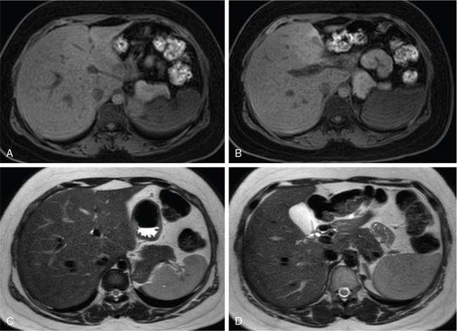
MRI

Anatomical variants of liver
1. Accessory fissures and diaphragmatic slips

Relevance
2. Sliver of liver

Relevance
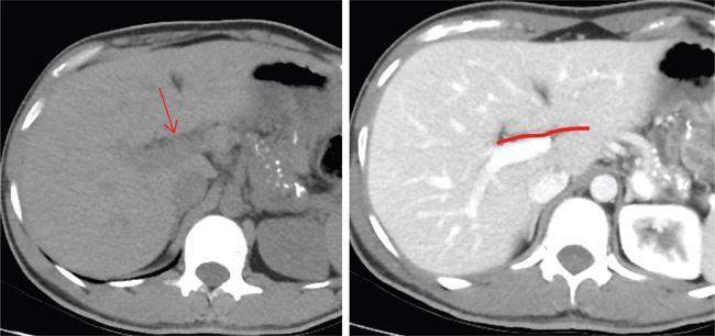
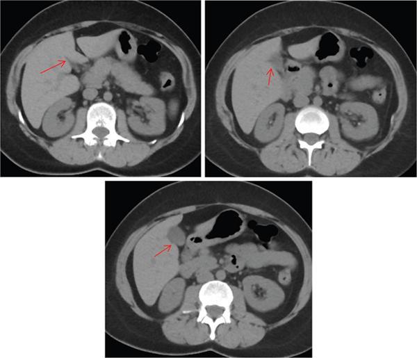
3. Papillary process of the caudate lobe
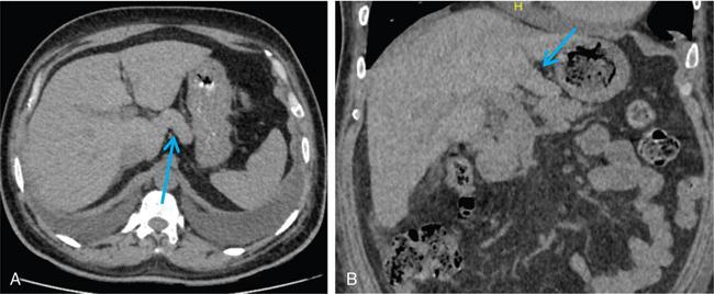
Relevance
Anatomic abnormalities
1. Riedel’s lobe
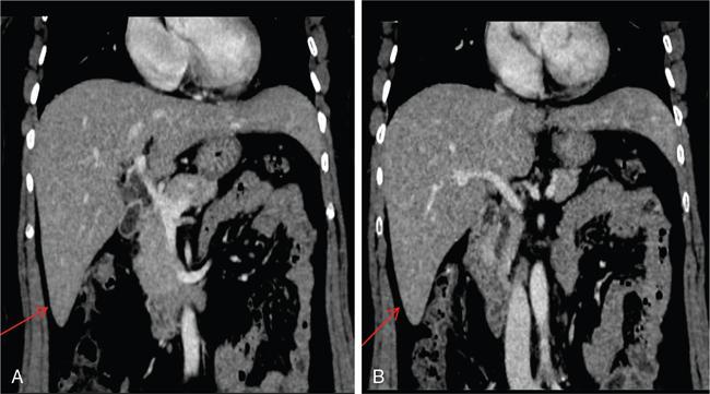
Relevance
2. Pedunculated accessory hepatic lobes
Diagnosis

Relevance and complications
Hepatic artery
Anatomy
Imaging
USG and colour doppler
CT/MRI
Hepatic arterial variants

Clinical relevance
1. Liver transplant
2. Tumour surgery

3. Placement of intraarterial chemotherapy pumps
Portal venous system
Related posts:
![]()
Stay updated, free articles. Join our Telegram channel

Full access? Get Clinical Tree


Radiology Key
Fastest Radiology Insight Engine