and the image resolution allows to differentiate primarily the internal and external surfaces of the abdomen. In addition, different masks identify the linea alba (LA), rectus abdominis (RA) and oblique muscles (OM). The oblique muscles comprises three different muscles: external oblique (EO), internal oblique (IO) and transversus abdominis (TA). Despite being independent anatomical units, their mechanical behaviour do not express separate movements. Hence, the whole thickness comprising the EO, IO and TA is considered a monolayer (composite) and only one anatomical unit is identified. This assumption does not alter the passive mechanical characterization of the abdominal wall.
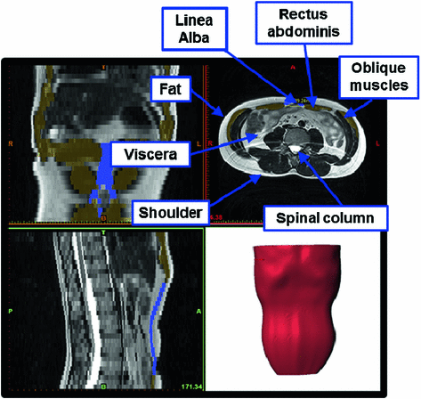
Fig. 1
Magnetic resonance imaging (MRI) from a healthy man aged 38 where the different anatomical structures are identified. The 3D model reconstruction is shown
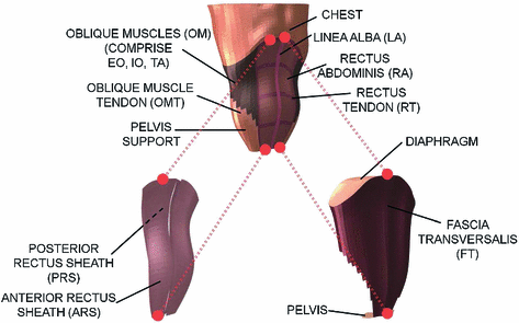
The segmentation of the different main muscles of the abdomen allows the definition of a three dimensional model. The meshing of the model is obtained using the commercial software ABAQUS . Specifically, a structured volumetric mesh was made employing a total of 13,200 hexahedral elements. The meshing considers 5 elements throughout the thickness of the wall so, according to the work published by Norasteh et al. [23], approximately 2 elements represent the EO, 2 elements represent the IO and the last one represents the TA. Apart from the abdominal muscles, the abdominal wall is comprised of aponeuroses (denoted by fascias or tendons too) that wrap muscles and are collagenous biological tissues [20]. To begin with, the anterior and posterior rectus sheaths (ARS and PRS, respectively) end in the midline of the abdomen forming the linea alba. The ARS and PRS come from the aponeuroses that wrap the oblique muscles. At the level of the oblique muscles, these fascias are supposed to be part of the composite previously defined. Besides, there is an internal aponeurosis covering the inner abdominal cavity, denoted by fascia transversalis. Numerically, 2,092 membrane elements which represent these aponeuroses are defined in the model. Likewise, some tendinous structures appear inside the rectus abdominis (rectus tendon, RT) and the oblique muscles (oblique muscle tendon, OMT) and they are identified in the structured hexahedral mesh (see Fig. 2).
 . Specifically, a structured volumetric mesh was made employing a total of 13,200 hexahedral elements. The meshing considers 5 elements throughout the thickness of the wall so, according to the work published by Norasteh et al. [23], approximately 2 elements represent the EO, 2 elements represent the IO and the last one represents the TA. Apart from the abdominal muscles, the abdominal wall is comprised of aponeuroses (denoted by fascias or tendons too) that wrap muscles and are collagenous biological tissues [20]. To begin with, the anterior and posterior rectus sheaths (ARS and PRS, respectively) end in the midline of the abdomen forming the linea alba. The ARS and PRS come from the aponeuroses that wrap the oblique muscles. At the level of the oblique muscles, these fascias are supposed to be part of the composite previously defined. Besides, there is an internal aponeurosis covering the inner abdominal cavity, denoted by fascia transversalis. Numerically, 2,092 membrane elements which represent these aponeuroses are defined in the model. Likewise, some tendinous structures appear inside the rectus abdominis (rectus tendon, RT) and the oblique muscles (oblique muscle tendon, OMT) and they are identified in the structured hexahedral mesh (see Fig. 2).
Fig. 2
Finite element model of the healthy human abdomen where the different anatomical structures are identified. Since different structures are superimposed anatomically, they are shown separately and the dotted lines indicate the geometrical correspondence
The anatomy of the abdomen includes other anatomical structures that close the abdominal cavity and allows the correct functioning of the different organs: the diaphragm and the pelvis. Those units are also defined in the reference model and 432 shell elements are added to the model using the software FEMAP (see Fig. 2).
 (see Fig. 2).
2.2 Herniated and Repaired Human Abdomen
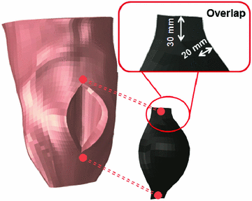
The previous FE model was used to develop a new FE model that represents a herniated human abdomen bearing a large incisional hernia along the linea alba [8]. The procedure followed to generate the large hernia consisted of separating some nodes of the FE model of the healthy abdomen and, after that, an internal pressure was applied and increased until the hernia defect measures  mm [27] (see Fig. 3).
 mm [27] (see Fig. 3).
Fig. 3
Finite element model of the herniated human abdomen and the surgical prosthesis. The procedure to place the mesh and the overlap between tissue and mesh is indicated
After the defect is created, the condition just after hernia repair surgery is modelled by placing a prosthesis covering the hernia. The prosthesis is modelled using a total of 165 membrane elements of 1 mm thickness [9] with the software 


 and its placement reproduces the onlay mesh technique [1]. The overlap between the surgical mesh and the abdominal tissues covers 3 elements of the numerical mesh on the lateral edges and 2 elements on the upper and lower sides of the prosthesis (see Fig. 3). The sutures are modelled through matched nodes between mesh and tissue.


 and its placement reproduces the onlay mesh technique [1]. The overlap between the surgical mesh and the abdominal tissues covers 3 elements of the numerical mesh on the lateral edges and 2 elements on the upper and lower sides of the prosthesis (see Fig. 3). The sutures are modelled through matched nodes between mesh and tissue.
3 Experimental Characterization
The laboratory experiments aim at collecting information about the mechanical response and this information is used as the basic input for constitutive modelling of tissues. The ideal goal is to develop mechanical tests that reproduce the physiological state that tissues works in. Experimental data derived from uniaxial tests could not be sufficient for the mechanical characterization of multidimensional material models aimed at predicting the behaviour in physiological loading states [11]. Hence, a faithful approach may be achieved by biaxial testing [13] and it may be even improved with inflation [28] or punching tests [14, 26]. However, having access to some testing equipment is not always possible and numerous studies in the literature report experimental studies based on uniaxial tests [13, 21, 22]. Likewise, experimental testing of soft tissues is somewhat limited since human specimens are not easy to obtain and physiological states are not usually reproduced in traditional testing. Furthermore, since human specimens are not easy to obtain, experimental animal models are frequently used.
Due to in clinical interventions for hernia repair surgical meshes are used, their mechanical behaviour needs to be addressed as well. In this Section experimental uniaxial testing of abdominal tissues and different prostheses are introduced.
3.1 Abdominal Tissues
The laboratory experiments were developed using New Zealand White rabbits, a frequently used animal model in the study muscle behaviour [2, 24]. The experimental protocol followed was described by Hernández et al. [6] who also obtained initial strains. With respect to the linea alba, two zones were differentiated for the study; the first one, located close to the rectus abdominis muscle and the linea alba, was composed of two muscles: the EO and the IO, whereas the second one, located close to the para-spinous muscle, comprised three muscles, namely, the EO, the IO and the TA (see Fig. 4). The experiments were performed without separating muscle layer so results refer to the composite material. For the mechanical testing, one sample in both the longitudinal and transversal directions were harvested from each of the zones of the tissue patch (see Fig. 4). Samples with a width/length ratio around 1/7 were cut in order to preserve the uniaxial tension hypothesis along both, longitudinal and transversal directions. The mechanical characterization was addressed throughout uniaxial tests under displacement control on an INSTRON 3,340 microtester with a 1 [kN] full scale load cell. An initial preconditioning, consisting of three cycles at a nominal strain of 40 %, was imposed to the samples so that the tissue was subjected to physiological loading states. The applied displacement rate was 5 [mm/min] in order to preserve quasi-static testing conditions.
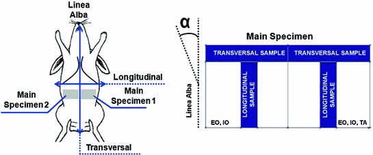
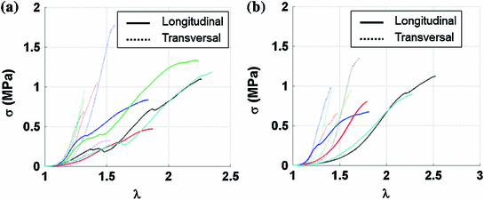

Fig. 4
On the left, experimental animal used (New Zealand White rabbit) and specimens extracted to characterize the abdominal muscle behaviour. On the right, scheme of the samples cut in the longitudinal and transversal direction. The angle  indicates the direction to define the preferential direction of material anisotropy
 indicates the direction to define the preferential direction of material anisotropy
Fig. 5
Cauchy stress-stretch curves obtained from the two studied areas shown in Fig. 4 which are composed of different muscle layers. The curves were truncated before the maximum stress point. Continuous and dotted lines show the results from the longitudinal and transversal samples, respectively. a External and internal obliques. b External and internal obliques and trasversus abdominis
Load and displacements were recorded until sample rupture from the tests to calculate the stretch of the sample as  , where
  is the initial length between the clamps and
  is the clamp displacement. Cauchy stress in the direction of the stretch was computed as
  , where
  is the applied load and
  is the cross sectional area. The Cauchy stress-stretch curves are represented in Fig. 5 for the different groups of studied samples (see Fig. 4) [6].
 , where
  is the initial length between the clamps and
  is the clamp displacement. Cauchy stress in the direction of the stretch was computed as
  , where
  is the applied load and
  is the cross sectional area. The Cauchy stress-stretch curves are represented in Fig. 5 for the different groups of studied samples (see Fig. 4) [6].
Fig. 6
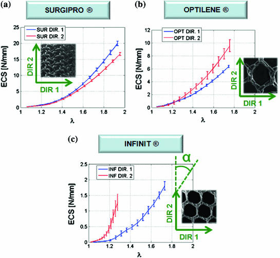
Macroscopic images and mechanical experimental results along directions 1 and 2 of the prostheses studied: a  , b
, b  and c
and c  . Note the angle
  which defines the preferential direction of anisotropy is shown in c [9]
 , b
, b  and c
and c  . Note the angle
  which defines the preferential direction of anisotropy is shown in c [9]
3.2 Surgical Prostheses
Despite the wide variety of surgical meshes offered in the market, only three non-absorbable, biocompatible surgical meshes were tested (see Fig. 6):  (SUR), a HW (
 ) polypropylene (PP) monofile mesh with a small pore size (
 );
);  (OPT), a LW (
 ) PP monofile mesh but with a large pore size (
 ); and
  (INF), a MW mesh (
 ) with a large pore size composed of a polytetrafluoroethylene (PTFE) monofilament (
 ). For the mechanical testing, two perpendicular directions (denoted by 1 and 2) were defined to determine the anisotropy of the materials and mesh samples tested were 20 mm wide by 190 mm long (see Fig. 6). The experimental protocol consisted of a uniaxial preload of 2 N and uniaxial loading, both applied with an INSTRON 5,548 microtester with a 50 N load cell [9]. Then a displacement rate of 10 mm/min was maintained until the rupture of the sample. The value of the thickness of the meshes cannot be defined due to its discontinuous cross sectional area including filaments and interspersed empty areas, so Cauchy stress (
 ) can not be computed. Thus, to compare the three meshes, force per unit width multiplied by stretch (Equivalent Cauchy Stress, ECS) was obtained using the expression
  , where Force(N) is the load applied during the test.
 (SUR), a HW (
 ) polypropylene (PP) monofile mesh with a small pore size (
 );
);  (OPT), a LW (
 ) PP monofile mesh but with a large pore size (
 ); and
  (INF), a MW mesh (
 ) with a large pore size composed of a polytetrafluoroethylene (PTFE) monofilament (
 ). For the mechanical testing, two perpendicular directions (denoted by 1 and 2) were defined to determine the anisotropy of the materials and mesh samples tested were 20 mm wide by 190 mm long (see Fig. 6). The experimental protocol consisted of a uniaxial preload of 2 N and uniaxial loading, both applied with an INSTRON 5,548 microtester with a 50 N load cell [9]. Then a displacement rate of 10 mm/min was maintained until the rupture of the sample. The value of the thickness of the meshes cannot be defined due to its discontinuous cross sectional area including filaments and interspersed empty areas, so Cauchy stress (
 ) can not be computed. Thus, to compare the three meshes, force per unit width multiplied by stretch (Equivalent Cauchy Stress, ECS) was obtained using the expression
  , where Force(N) is the load applied during the test.
Figure 6 provides the mean ECS versus stretch curves obtained in the mechanical tests for SUR, OPT and INF, respectively. Significant differences were addressed between the three different prostheses; SUR emerged as the stiffest mesh with an isotropic behaviour, OPT mesh showed an anisotropic mechanical response and finally INF mesh emerged as a highly anisotropic prosthesis.
4 Constitutive Modelling
Biological soft tissues are subjected to large deformations with negligible volume changes due to high water content and show an anisotropic mechanical response due to their internal structure. The extra-cellular matrix is composed of a network of collagen, elastin and muscular fibres embedded in a more or less isotropic ground substance. Experimental evidence shows that abdominal muscles subjected to axial tensile stresses have a typical non-linear response, with an initial low stiffness toe region, a linear part with approximately constant stiffness, and a third region corresponding to progressive failure of the composing fibres [6].
Usually, the description of the constitutive behavior of this type of material relies on the identification of an appropriate strain energy density function (SEF) from which stress-strain relations and local elasticity tensors are derived. The laboratory experiments needed to define the SEF that characterize the mechanical response of abdominal tissues and surgical prostheses are those described in the previous sections.
Even though different SEFs have proved to be successful for particular applications and for describing many of the material properties, their use is limited, in most cases, to the range of physiological loads. Hence, the SEFs proposed for both, abdominal tissues and surgical meshes, have been showed a good agreement with the experimental results within the physiological range. However, viscoelastic effects in muscle tissues were despised.
4.1 Anisotropic Hyperelastic Model
A brief review of basic concepts needed to establish the formulation within the large hyperelasticity theory is provided in this Section.
Let consider a continuum body with reference configuration  at the initial reference time
  and let assume a motion
  which maps this configuration to the current configuration
  at each time
  . Hence, a point
  transforms to a point
  , where
  and
and  define the respective positions of a particle in the reference and current or deformed configurations relative to a global coordinates. The direction of anisotropy given by collagen fibres at a point
  is defined by a unit vector field
  ,
,  . Then, the stretch of the fibres is defined as:

The SEF that allows the formulation of the elastic constitutive law for anisotropic materials,  , explicitly depends on both the right Cauchy-Green tensor
  [12, 25, 29] and the fibres direction
  in the reference configuration:

where 


 at the initial reference time
  and let assume a motion
  which maps this configuration to the current configuration
  at each time
  . Hence, a point
  transforms to a point
  , where
  and
and  define the respective positions of a particle in the reference and current or deformed configurations relative to a global coordinates. The direction of anisotropy given by collagen fibres at a point
  is defined by a unit vector field
  ,
,  . Then, the stretch of the fibres is defined as:
(1)
 , explicitly depends on both the right Cauchy-Green tensor
  [12, 25, 29] and the fibres direction
  in the reference configuration:
(2)

Stay updated, free articles. Join our Telegram channel

Full access? Get Clinical Tree


