(1)
where h is the Planck constant (value: 4,135 × 10−15 eVs).
These properties allow X-rays to interact with the different tissues of the human body: once they have been generated from an X-ray source and have crossed the patient’s body, emerging X-rays hit a detection system, interact with it and create an image which can be read by radiologists.
Various sources can generate X-rays; in 1913 William David Coolidge, a researcher of General Electric Company, invented the so-called “X-ray Coolidge Tube” which represents still today the model on which are designed modern X-ray sources (Fig. 1).
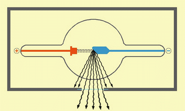

Fig. 1
This picture shows the Coolidge tube model: the electrons created on the cathode (+) for thermionic effect, are accelerated and hit the tungsten plate of the anode (−). An X-rays-beam is generated from this interaction. The X-rays can only goes out from the opening of the tube not covered by the lead
The general principle of Coolidge Tube is very simple: in a vacuum tube are placed a cathode and an anode (both made of tungsten, an element with high atomic number) with a difference in potential (ΔV 1 ) created between them:
1.
The cathode consists of a little pigtail wire in which flows an electric current generated by a little potential difference (ΔV 2 ). This wire is heated because of the Joule effect.
2.
The anode consists of a plate of tungsten.
Thanks to the ΔV 1 between the two electrodes, electrons generated for thermionic effect from the pigtail wire are accelerated and an “electron beam” travels through the vacuum from the cathode to the anode with an incredible speed. The kinetic energy of the impact of the “electron beam” is converted into heat for 99 %, the other 1 % as “X-ray beam”.
This X-ray beam has its own intensity and the X-rays which it consists of have their own average energy. It is made of two kinds of X-rays, bremsstrahlung X–rays and characteristic X–rays (Fig. 2):
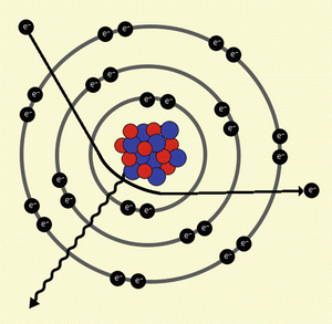

Fig. 2
This picture shows the interaction of an electron with the inner orbitals, characterised by the deceleration of the electron, the deflection of the trajectory, and the emission of an X-ray (Bremsstrahlung X-ray)
Bremsstrahlung X–rays: these are produced by the deceleration and deflection of electrons emitted from the cathode when they hit the crystal lattice of the anode. This kind of X-rays is that produced more during an “electron-beam” collision.
Characteristic X–rays: these are produced after the collision of electrons emitted from the cathode with the electrons of inner orbital of the atoms that constitute the anode (in this case tungsten).
We must point out that the entire process is probabilistic, since a single electron could be decelerated and deflected by outer or inner orbitals of the tungsten atoms of the anode, creating single X-rays with different frequency (and thus energy). Actually the number of electrons and X-rays generated is so great that we consider the average value of energy of every single X-ray of the beam; thus we talk in terms of “X–ray beam”, “intensity of the X–ray beam” and “energy of X–rays”.
The intensity of the X – ray beam can be considered as “ the number of X-rays ” emitted from the source; its value depends on the amount of electrons emitted from the cathode (i.e. the charge of the cathode): we can increase X-rays number, and thus of the intensity of the X-ray beam, increasing the charge (q) of the cathode, according to the formula (2):

where t is the time and ΔV 2 is the difference in potential between the two ends of the pigtail wire of the cathode. The unit of measure of the X-rays intensity is mAs (1 mAs = 10 −3 C (Coulomb)). Greater the total charge, greater the number of electrons emitted for thermionic effect, greater the intensity of X-ray beam, greater the definition of the image, greater the total ionising dose ( TID ) given to the patient. In daily practice, in order to obtain a greater charge (and thus X-ray beam intensity), we modify in particular the ΔV 2 value.

(2)
The energy ( E ) is the average “ strength ” or the “ passing ability ” of the single X – rays of which the beam is made of; it depends on Eq. (3):

where q is the charge and ΔV 1 is the potential difference between the electrodes. The unit of measure is keV (1 keV = 1.6 × 10 −16 J (Joule)). Since the charge of a single electron is constant and it is 1.6 × 10⁻¹⁹ C (Coulomb), if we want X-rays with greater energy, we have to increase the potential difference ΔV 1 . High energy X-rays (hard X–rays) are generated for high ΔV 1 values, whereas low energy X-rays (soft X–rays) are generated for low ΔV 1 values. Harder X-rays have greater capability to penetrate through the patient and reach the detection system.

(3)
X-rays at different energies interact in different ways with human tissues, depending on their composition.
Radiology technicians can modify these two parameters (intensity of X-ray beam and X-ray energy) to obtain an optimal image, both in traditional radiology and CT (see below).
Once the X-rays emerge from the Coolidge tube, they interact with human tissues, in a probabilistic way. This interaction will be different based on the density and atomic composition of the tissue. Possible interactions are the following:
1.
X–rays scattering: X-rays are deflected in all the directions by the crystalline lattice of the tissues. This kind of interaction is responsible for the scattered effect of the image, the so-called “noise” of an image (see below).
2.
Photoelectric effect (Fig. 3a): an X-ray hits an electron of the inner orbitals of an atom and gives it all his energy; this results in the ejection of the electron from its orbital, and the ionisation of the atom.
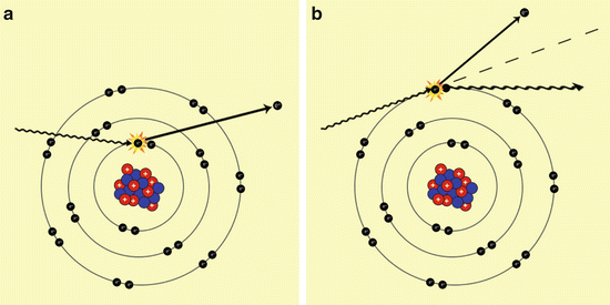

Fig. 3
These pictures show the most important interaction of X-rays with the atoms of the human-body. In (a) is shown the “Photoelectric effect”, characterised by the fact that the X-ray interact with an electron of the inner orbitals, throwing it out. In (b) is shown the “Compton effect” in which the X-ray interacts with an electron of the outer orbital, resulting in a loss of energy and deflection of its trajectory, and in a emission of the electron hit
3.
Compton effect (Fig. 3b): an X-ray hits an electron of the outer orbitals of an atom and gives it a part of its energy (less energy is required to eject an electron from outer orbitals than the inner orbitals): this interaction results in the ejection of the electron outside the atom and the deflection and loss of energy of the X-ray.
4.
Couple production: an X-ray interacts near the atomic nucleus, and this led to a production of a couple which consists of electron and positron (This kind of interaction happens only for high X-ray energy, greater than 1.02 MeV; these energies are not used in traditional radiology and CT).
Photoelectric and Compton effects are important because they explain the ionising capability of X-rays, responsible for undesirable effects (teratogenic effects, mutagenic effects) which limit use of X-rays in clinical practice (in particular in pregnancy) according to stochastic and non-stochastic effects on the tissues (see below).
When an X-ray beam crosses a patient’s body, it loses its intensity according to the principles just exposed, and reaches a detection system placed over human body, with intensity (I) lesser from the original (I 0 ) as we can see in the formula (4):

where I is the intensity of X-ray beam emerging from the patient, I 0 the intensity of X-ray beam originated from the source, e the Euler number, μ the linear attenuation coefficient (different for every tissue based on their composition) and x the tissue thickness.

(4)
Applications of X-Rays in Clinical Practice [2, 3]
All the concepts exposed before are the basic physical principles that permit to explain how it is possible to obtain an image (a radiograph, a fluoroscopic image or a CT) using X-rays. Now we quickly expose the most important applications of X-rays in clinical practice.
In traditional radiology X-rays originated from a Coolidge tube once have crossed human body reach a detection system: this detection system originally was a photographic film impressed by X-ray beam, while nowadays it is a radiographic cassette made of photo–stimulate phosphors read by a laser optic viewer after the execution of a radiograph, or a plane made of digital sensors, which once has detected the X-rays displays directly digital images on a monitor. The images obtained are two-dimensional (2D) static images called radiographs, and they do not allow to discriminate the three-dimensional (3D) arrangement of body structures.
In fluoroscopy, X-rays emerging from human body were detected originally by a fluorescent screen, while nowadays they are detected by an X–ray image intensifier and a CCD camera; in this way, images are displayed on a monitor in real time. This technique allows to obtain dynamic 2D images, used for such examinations as angiographies in which the operator needs to follow the diffusion of a contrast medium or radiopaque objects (catheters, coils …) along the body structures in diagnostic and, above all, therapeutic procedures.
Computed Tomography (CT) allows to obtain sectional axial images of the body and, in modern CT scanners, thanks to the spiral acquisitions, multiplanar sectional and 3D images of the body.
Introduction to CT [4]
In 1970s, thanks to the work of Sir Godfrey N. Hounsfield and Dr. Conmark, winners of the Nobel Prize in 1979, CT was introduced in clinical practice. It was a revolution because of its incredible capability in diagnosis and management of patient.
The great contrast resolution (the ability to detect in an image two different points with different degrees of intensity—in b/w images, shades of gray), spatial resolution (the ability to distinguish two different points next to each other—the lesser the distance between two points, the higher the spatial resolution) and temporal resolution (the time for acquisition of a frame) of modern CT scanner, in particular in the evaluation of soft tissue, make CT an essential instrument for detection and staging of various pathological conditions.
In fact, traditional X-ray radiographs are still important instruments to assess patient condition, but cannot offer a complete evaluation; moreover, CT’s intrinsic capability to explore deep organs despite ultrasonography (US) and its very low execution time than Magnetic Resonance (MR) allow us to have many and detailed information in a very little time. Anyway, we must remember CT uses ionising rays that can have mutagenic effects on human tissues (with increased risk of neoplasms and, in pregnant women, of foetal malformations and spontaneous abortions).
How a CT Scanner Is Made [4, 5]
CT uses X-rays to produce a series of images that will be analysed by the radiologist.
Modern CT scanner consists of (Fig. 4):


Fig. 4
This picture shows the parts of which a Modern CT scanner is made: the control console (1), the circular gantry (2) and the moving table (3)
Circular gantry
Moving patient table
Control console
The circular gantry consists of a solid structure containing an X–ray source (made based on a Coolidge tube, see above) and a detection system, firmly connected opposite to each other forming a 180° angle between them, and a rotation system that rotates the X-ray source and detection system by a 360° angle. Thanks to the “slip rings” technology, a wireless electrical connection, the X-ray source-detection system complex can rotate continuously over 360° degrees (allowing the “helical scanning”, see below). Detection system is connected with a data-acquisition-system (DAS) which converts X-rays in electric pulses that will be analysed and managed by the computer to create an image series. Moreover, the circular gantry contains a laser sighting system to correctly position the patient in the moving patient table, and an important cooling system to dissipate the great heat generated by the X-ray source.
The moving patient table carries the patient into the gantry hole.
The control console is managed by the radiology technician, who controls the whole procedure supported by the radiologist.
General Acquisition Principles [1, 4, 6]
The general principle is very simple : X – rays , generated from a rotating X – ray source placed in the circular gantry , cross the patient body lying on the moving table in the centre of the gantry and are detected by the detection system placed opposite to the X – ray source (Fig. 5). The X-ray beam generated at a known intensity value, equal for every degree of rotation, reaches detection system with an intensity value less than that at the source because of the interaction with human body structures, according to the formula (5) derived from the formula (4):
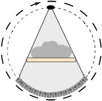
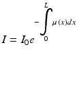

Fig. 5
This picture shows the general principles of a CT scan: the patient lies on the moving table, and an X-ray beam generated by the X-ray tube crosses the patient’s body. Once they have crossed the patient, they interact with the detection system placed opposite to the X-ray source. The X-ray tube and the detection system rotate together around the patient

(5)
This formula indicates that the intensity of X-ray beam measured by the detector (I) is equal to the product of the intensity of X-ray beam originating from the source (I 0 ) multiplied by the Euler number (e) elevated to the integral of every X-ray linear attenuation coefficient (μ(x)) from the origin (0) to (L), where L is the distance between the source and the detector covered by the beam.
X-ray beam generated from the rotating source when crossing human body and its deep structures interacts with tissues and yields them energy; this interaction is different depending on tissue composition (water, blood, lipids, bone and crystalline structures) and the rotation degree of the source.
Detection system is made of different detectors. Although early CT scanners used gas ionisation-detectors, in modern CT scanners detection system consists of solid-state detectors made of ceramic of rare-earth oxides, which have high capture efficiency (total amount of emerging X-rays absorbed by the detector) and conversion efficiency (capability to accurately convert X-rays into electric signal). Detectors are aligned side by side, divided by thin septa made of tungsten to minimise the “noise” of the image (i.e. artefacts from scattered radiation generated by X-rays interaction with body structures), and are able to capture the greatest amount of X-rays emerging from the patient. Once the X-ray beams emerging from human body reach the detection system with intensity value I, they are transformed into electric pulses by the data–acquisition–system (DAS). These electric pulses, converted into data series, will be then processed and analysed by the computer, and then converted into axial images series.
CT Generations [4, 5]
From an engineering point of view, we describe four generations of CT scanner (Fig. 6).
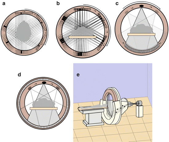

Fig. 6
This picture shows the five generations of CT scanners. The third generation scanners are the most diffuse in clinical practice nowadays
1.
First generation
The first CT scanner (MARK 1) was made by EMI in 1972. It was only a head scanner, and required about 20 min to obtain a complete axial scan of the head, with a slice thickness of 13 mm. It consisted of a box-shaped gantry in which lay the head of the patient, an X-ray beam source generating a very narrow beam, and a detection system containing a couple of detectors placed against each other in two adjacent rows to scan two slices concurrently and reduce acquisition time. The complex X-ray source—detection system scanned the head moving in the gantry according to a translation–rotation process, in which were sampled 160 detection data by a translation movement of the system for every degree of rotation, and an overall 180° rotation.
2.
Second generation
This generation differs from the first because of the use of an X–ray narrow cone beam and of a detection system with multiple detectors (from 3 for the first model up to 20 for the latest); the detectors are not placed on multiple rows, but on a single row. The complex X-ray source–detection system moved according to a translation–rotation movement. The CT scanner was implemented with a moving table, a laser indicator and the capability to tilt the gantry, allowing not only the head scan, but also the body scan for the first time. Scanning time was lesser than first generation, allowing to scan one slice of the chest holding one breath; there were still severe movement artefacts, and to limit them it was necessary to avoid the translation movement, maintaining the rotation movement.
3.
Third generation
In principle, the power supply of CT scanners was provided by electric cables which limited the movement of the system constituted by the complex X-ray source–detection system: in fact, after a 360° rotation, the system had to stop and then re-start moving in the opposite verse. This limitation allowed only sequential axial scans.
In the third generation of CT scanners has been introduced the “slip rings” technology. It has been a revolution. In fact, with the introduction of this technology, electric cables have been abolished, allowing a continuous rotational movement of the system, over the 360°, and abolishing the need of a translation–rotation movement. A new era of Helical CT started (see below).
Another improvement in CT technology that led to further decrease of scan timing has been the use of a detection system which consists of multiple detectors placed not on a single slice but on multiple slices, so that the use of cone-beam X-rays covers a greater section of the body in little time; this is the multislice–CT technology (see below).
Nowadays, the principal manufacturers produce only multislice CT scanners with this kind of architecture, which allows to generate sequential or helical CT scans.
4.
Fourth generation
The fourth generation has not had a great impact. In fact, high production costs were a limitation for its development. It differed from third generation in the architecture of the detection system: in fact detectors cover entirely the inner part of the gantry, and only the X-ray source (placed adjacent to the detectors and slightly inclined to them) rotates in the gantry.
5.
Fifth generation
Electron beam computed tomography (EBCT) was developed to evaluate heart. It consisted of a cathode that generated an electron beam, diverted and rotated by an electromagnetic fold; the electrons hit four semicircular anodes placed around the patient, generating X-rays captured by detectors placed adjacent to the anodes. Despite the high temporal resolution (about 50 ms), EBCT did not have great success due to high costs and intrinsic technician limitations.
Spiral-Volume Scanning and Multislice-CT [2–7]
With the introduction of “slip rings” technology in 1987, a new era started in CT. In fact, the capability to have a continuous rotating movement allowed not only to achieve faster scans in lower time but also multiaxial images. Before this innovation, scanners allowed to obtain only axial images for the limited movement of the complex X-ray source–detection system because of electric cables; in fact CT scanners were able to execute only axial sequential scans (slice–by–slice).
Third generation CT scanners with “slip rings” technology work with a continuous rotating movement of the complex X-rays-source–detection system; while the complex rotates, the table moves consensually along the z-axis (the longitudinal axis of the patient; the other two axes, x and y, are perpendicular to z-axis and represent the coordinates of axial images). This innovation, together with improvements in computing calculation speed, took CT scanner to a higher level, and in the early 1990s, Kalender et al. [5] developed the algorithm of spiral volume scanning (Spiral or Helical–CT) (Fig. 7).
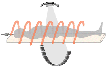

Fig. 7
This picture shows the principle of the helical-CT: the scan can be acquired with the patient placed on a moving table which moves during the continuous rotation of the complex X-ray tube. detection system around the patients. This continuous rotation with an angle >360° is possible thanks to the slip rings technology
Beside the introduction of “slip rings” technology, researchers developed a new system to improve Helical-CT scan faster than before. The idea was to create a new detection system, or better, to improve the old detection system in order to obtain more data in less acquisition time. The engineers created a detection system made of not only a single array of detectors (slice), but multiple rows of detectors, aligned in arrays, side by side. This detection system is able to capture X-rays-beam in a wider range along the z-axis. These scanners are called multislice–CT (MSCT) scanners. Nowadays there are CT-scanners capable to cover in a single rotation a field of view of 128 mm, using 256-rows detectors in a 0.5 s rotation time; this means that in 1 s it can cover a body section of about 26 cm, and a slice thickness of 0,675 mm, very impressive!
Stay updated, free articles. Join our Telegram channel

Full access? Get Clinical Tree


