The technical requirements for magnetic resonance imaging (MRI) of the breasts are challenging because high temporal and high spatial resolution are necessary. This article describes the necessary equipment and pulse sequences for performing a high-quality study. Although imaging at 3-Tesla (T) has a higher signal-to-noise ratio, the protocol needs to be modified from the 1.5-T system to provide optimal imaging. The article presents the requirements for performing breast MRI and discusses techniques to ensure high-quality examinations on 1.5-T and 3-T systems.
Dynamic contrast-enhanced (DCE) magnetic resonance (MR) imaging of the breast is a highly accurate imaging tool for the detection of primary and recurrent breast cancer, with reported sensitivities in the range of 83% to 100%. The American Cancer Society recommends that women with a lifetime risk of breast cancer greater than 20% undergo an annual MR imaging screening examination in addition to screening mammography. A recent American College of Radiology (ACR) Imaging Network trial supports the role of MR imaging in staging women who have biopsy-proven cancer. The demand for contrast-enhanced breast MR imaging in these patient populations continues to increase. A 2008 survey of radiology practices in the United States showed that breast MR imaging was offered at 74% of 754 surveyed practices. Given increased demand, it is predicted that additional radiology practices will offer this examination in a screening and diagnostic setting in the near future.
Increased clinical use of breast MR imaging has also been facilitated by the standardization of interpretation and reporting among radiologists. In 2003 the ACR published the fourth edition of the Breast Imaging Reporting and Data System (BI-RADS) manual, which contained the first edition of the MR Imaging Lexicon. The BI-RADS MR Imaging Lexicon provides a common language for describing findings and allows radiologists to communicate findings to referring physicians in a uniform, clear, and concise fashion.
At present, one of the challenges that breast MR faces is the wide range of specificities, ranging from 29% to 100%. A reason for this variable specificity is that the technical aspects of performing breast MR imaging have not been standardized. Most of the technical parameters, including equipment (magnet strength and breast coil), spatial and temporal resolution, pulse sequences, and timing of the dynamic contrast sequences, vary widely between practice sites. To address these issues, the ACR and the European Society of Breast Imaging have developed practice guidelines and technical standards for breast MR imaging, updated in 2008. The ACR is also developing a breast MR accreditation program, which will include technical requirements for optimizing this examination. Further improvement and standardization of the imaging protocol should lead to improvements in the characterization of lesions detected on breast MR imaging. This article reviews the basic principles of DCE breast MR imaging and discusses the technical parameters necessary for a high-quality examination. The article also discusses the advantages, limitations, and considerations for performing breast MR imaging at 3T.
Patient factors
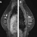
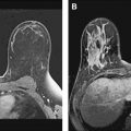
Given the wide overlap of breast cancer presentations on MR imaging, an effective approach to breast MR imaging protocol must include a multisequence assessment of benign and potentially malignant lesions. In premenopausal women, the MR imaging examination should be performed during the second week of the menstrual cycle (days 7–14), because uptake of contrast medium is dependent on the phase of the menstrual cycle. Good positioning of the patient is another essential factor for a high-quality study. It is essential for the patient to be comfortable and to have both breasts symmetrically centered within the coil. Both breasts are placed as deeply in the coil as possible with the nipples pointing downward. More breast coverage may be obtained by placing both arms at the side of the body and not above the patient’s head. The authors apply mild compression of breasts in the medial to lateral direction to decrease motion artifact and to decrease the number of slices needed to cover each breast (we scan in the sagittal plane) ( Fig. 1 ). Whenever possible a female technologist positions the patient in the coil for screening and/or diagnostic breast MR imaging examination. A female MR technologist always assists the authors with MR-guided interventional procedures because the breasts may need to be manipulated to visualize the index lesion. Most MR technologists have been trained to position the breast by observing stereotactic biopsies (performed on a prone table device). Once the patient has been positioned, localizer images are obtained. The technologist reviews these scout images to ensure that both breasts have been included in their entirety and are centered within the coil ( Fig. 2 ). During the study, images from each sequence are reviewed by the technologist as they are processed to ensure optimal image quality and to evaluate for additional MR applications (eg, diffusion, spectroscopy). Suboptimal sequences are repeated by the technologist.


Equipment: magnet and coil
Conventional breast MR imaging is routinely performed on 1.5T magnets, 3T magnets, and some lower-field dedicated breast magnets. The technical requirements for breast MR imaging at 1.5T are listed in Table 1 , which appears at the end of this article, and are reviewed later. Although there are no guidelines for performing the examination at 3T, the authors assume that imaging parameters at 3T should also meet the minimal technical requirements for a breast MR imaging performed on a 1.5T magnet. For an in-depth discussion of the technical aspects of breast MR imaging, see Ref.
| High magnetic field strength with good magnetic field homogeneity across both breasts |
| Dedicated bilateral breast coil with prone positioning |
| Full coverage of both breasts |
| Homogenous fat suppression over both breasts |
| Selection of a phase-encoding direction to minimize artifacts |
| 3D contrast-enhanced T1-weighted gradient echo sequences a |
| Short acquisition times of 1–2 minutes. Use the shortest possible TRs and TEs to keep total acquisition time short |
| Intravenous administration of a gadolinium chelate at a dose of 0.1 mmol/kg at a rate of 1–2 mL/s |
| Section thickness 1–3 mm b |
| High in-plane resolution (<1 mm × 1 mm) |
| High SNR per pixel |
| High temporal resolution (1–2 minutes) |
| Continuous dynamic imaging for 6–7 minutes |
| Subtraction or fat suppression |
a Ideally with parallel imaging sequences, with an acceleration factor ≤2.
b With technologic improvements, thin slices ≤1 mm may be achieved.
Proper dedicated equipment is necessary to optimize a breast MR imaging examination. The use of dedicated bilateral breast coils and high-field magnets are 2 essential components of this study, and are discussed in this section. A high signal-to-noise ratio (SNR) is a highly desirable variable in diagnostic breast MR imaging to maximize lesion characterization. The SNR is directly proportional to magnetic field strength (B o ), which at high strengths also affords higher spatial resolution. A high magnetic field also ensures adequate signal homogeneity and application of chemically selective fat suppression. The field homogeneity may be suboptimal for low-field magnets, resulting in uneven fat suppression and image degradation and it may impair lesion conspicuity.
A dedicated breast coil system that can image both breasts with the patient in the prone position enhances the clinical usefulness of breast MR imaging ( Fig. 3 ). Advances in multichannel radiofrequency (RF) coil design have greatly improved signal homogeneity; they also provide a higher SNR ( Fig. 4 ). Typically, 4-channel bilateral breast coils are matched to maximize parallel imaging techniques (discussed in the next section), although recent advances have pushed the coil array up to 32 receiver coils. In most clinical departments, a multipurpose body coil can be used as the transmit coil, whereas the dedicated breast coil is used as the receiver coil. Mediolateral coil selection with open design also provides added interventional flexibility, allowing access for MR-guided core needle biopsy or wire localization in complex cases. In addition, given the imaging time required for diagnostic breast MR imaging and the marked degradation of image quality with patient motion, coil comfort with judicious padding and streamline design while providing adequate compression are added considerations in coil selection.


Although unilateral breast coils are available, bilateral coil design is highly desirable for modern imaging, especially in those patients with known carcinoma. Comparison of physiologic fibroglandular enhancement between breasts can often serve as an internal standard, particularly in premenopausal midcycle and postmenopausal women receiving hormonal therapy. In addition, in those patients with known carcinoma, evaluation of the contralateral breast, axilla, and chest wall can aid in preoperative staging. Bilateral breast imaging also reduces wraparound artifacts found in unilateral imaging when the contralateral breast falls out of the field-of-view (FOV). Wraparound artifact occurs when the FOV is too small, and the signal from tissue outside the selected FOV wraps around or aliases into the acquired image ( Fig. 5 ). Therefore, the selected FOV should be large enough to include full coverage of both breasts and to maximize spatial resolution. In addition, special techniques such as phase oversampling can be used to mitigate wrap artifact, albeit at the expense of the SNR.
Equipment: magnet and coil
Conventional breast MR imaging is routinely performed on 1.5T magnets, 3T magnets, and some lower-field dedicated breast magnets. The technical requirements for breast MR imaging at 1.5T are listed in Table 1 , which appears at the end of this article, and are reviewed later. Although there are no guidelines for performing the examination at 3T, the authors assume that imaging parameters at 3T should also meet the minimal technical requirements for a breast MR imaging performed on a 1.5T magnet. For an in-depth discussion of the technical aspects of breast MR imaging, see Ref.
| High magnetic field strength with good magnetic field homogeneity across both breasts |
| Dedicated bilateral breast coil with prone positioning |
| Full coverage of both breasts |
| Homogenous fat suppression over both breasts |
| Selection of a phase-encoding direction to minimize artifacts |
| 3D contrast-enhanced T1-weighted gradient echo sequences a |
| Short acquisition times of 1–2 minutes. Use the shortest possible TRs and TEs to keep total acquisition time short |
| Intravenous administration of a gadolinium chelate at a dose of 0.1 mmol/kg at a rate of 1–2 mL/s |
| Section thickness 1–3 mm b |
| High in-plane resolution (<1 mm × 1 mm) |
| High SNR per pixel |
| High temporal resolution (1–2 minutes) |
| Continuous dynamic imaging for 6–7 minutes |
| Subtraction or fat suppression |
a Ideally with parallel imaging sequences, with an acceleration factor ≤2.
b With technologic improvements, thin slices ≤1 mm may be achieved.
Proper dedicated equipment is necessary to optimize a breast MR imaging examination. The use of dedicated bilateral breast coils and high-field magnets are 2 essential components of this study, and are discussed in this section. A high signal-to-noise ratio (SNR) is a highly desirable variable in diagnostic breast MR imaging to maximize lesion characterization. The SNR is directly proportional to magnetic field strength (B o ), which at high strengths also affords higher spatial resolution. A high magnetic field also ensures adequate signal homogeneity and application of chemically selective fat suppression. The field homogeneity may be suboptimal for low-field magnets, resulting in uneven fat suppression and image degradation and it may impair lesion conspicuity.
A dedicated breast coil system that can image both breasts with the patient in the prone position enhances the clinical usefulness of breast MR imaging ( Fig. 3 ). Advances in multichannel radiofrequency (RF) coil design have greatly improved signal homogeneity; they also provide a higher SNR ( Fig. 4 ). Typically, 4-channel bilateral breast coils are matched to maximize parallel imaging techniques (discussed in the next section), although recent advances have pushed the coil array up to 32 receiver coils. In most clinical departments, a multipurpose body coil can be used as the transmit coil, whereas the dedicated breast coil is used as the receiver coil. Mediolateral coil selection with open design also provides added interventional flexibility, allowing access for MR-guided core needle biopsy or wire localization in complex cases. In addition, given the imaging time required for diagnostic breast MR imaging and the marked degradation of image quality with patient motion, coil comfort with judicious padding and streamline design while providing adequate compression are added considerations in coil selection.
Although unilateral breast coils are available, bilateral coil design is highly desirable for modern imaging, especially in those patients with known carcinoma. Comparison of physiologic fibroglandular enhancement between breasts can often serve as an internal standard, particularly in premenopausal midcycle and postmenopausal women receiving hormonal therapy. In addition, in those patients with known carcinoma, evaluation of the contralateral breast, axilla, and chest wall can aid in preoperative staging. Bilateral breast imaging also reduces wraparound artifacts found in unilateral imaging when the contralateral breast falls out of the field-of-view (FOV). Wraparound artifact occurs when the FOV is too small, and the signal from tissue outside the selected FOV wraps around or aliases into the acquired image ( Fig. 5 ). Therefore, the selected FOV should be large enough to include full coverage of both breasts and to maximize spatial resolution. In addition, special techniques such as phase oversampling can be used to mitigate wrap artifact, albeit at the expense of the SNR.
Pitfalls and technical artifacts
As discussed earlier, voluntary patient motion greatly limits diagnostic MR image quality. Respiratory and cardiac motion may degrade image quality. Because motion always propagates in the phase-encoding direction, proper selection of the phase-encoding direction minimizes artifact from cardiac and respiratory motion. For breast MR imaging, the correct choice of the phase-encoding direction is left to right for axial images and superior to inferior for sagittal images. Prone positioning of the breasts decreases wraparound artifacts, and affords dependent positioning of the breasts with minimal cardiac and respiratory interference. In addition, prone positioning separates the breast parenchyma from the chest wall, increasing conspicuity of the fibroglandular tissue and chest wall interface. Coil selection is a balance between SNR, signal uniformity, interventional access, patient comfort, and cost.
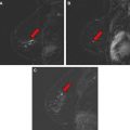
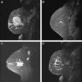
Fat has a high signal on MR imaging and may obscure enhancing masses on the postcontrast images ( Fig. 6 ). To increase lesion conspicuity most European techniques rely solely on subtraction of the postcontrast from the precontrast images to identify suspicious enhancing lesions. Subtraction is a postprocessing technique that subtracts a precontrast data set from a postcontrast data set on a pixel-by-pixel basis. The subtraction images are created automatically on the scanner. The advantages to using subtraction technique include no loss of signal, independence from magnetic field homogeneity, and no increase in scanning time. However, the SNR is low on the subtracted images, and the images may be plagued by misregistration from patient motion and automated technique error in slice positioning. In the United States, lesion conspicuity is enhanced by a chemically selective fat suppression to make the fat signal null. With both approaches, significant motion artifact during the dynamic phase causes misregistration and leads to the appearance of falsely enhancing lesions or nonvisualization of enhancing lesions ( Fig. 7 ). At the authors’ institution, we use fat suppression and subtraction in the evaluation of the dynamic postcontrast images.
Chemical shift artifact and magnetic susceptibility may also affect image quality. Chemical shift artifact is misregistration of spatial information caused by difference in the resonant frequency of water and fat. This artifact is seen in the frequency encoding direction, and is a result of incorrect mapping of the signal from lipid relative to that of water. The number of pixels over which the chemical shift occurs is dependent on the bandwidth per pixel of the imaging sequence. It can be corrected by increasing the bandwidth and by using fat suppression techniques. Magnetic susceptibility artifact is caused by the presence of an object in the FOV with a higher or lower magnetic susceptibility. It is most noticeable around metallic objects, and the size of the artifact is dependent on the size and composition of the metallic object. This artifact appears more prominently on the gradient echo sequences, commonly used in DCE breast MR imaging. Most breast biopsy clips are now made of titanium, and the presence of a metallic clip may be difficult to identify on MR images.
Imaging protocol
Sample DCE breast MR imaging protocols at 1.5T and 3T are presented in Tables 2 and 3 appearing at the end of this article. The parameters listed are guidelines; clinical practices may need an experienced MR technologist to modify the protocol on a case-by-case basis. At the authors’ institution, a precontrast T1-weighted image without fat saturation is first obtained. This sequence is useful to identify regions of fat in benign lymph nodes or fat necrosis. It also serves to delineate anatomic landmarks in problem cases in conjunction with other sequences. In addition, regions of subtle architectural distortion are often better characterized on this sequence. Moreover, the authors find it easier to identify the metallic clips deployed to demarcate biopsy sites on this sequence compared with the gradient echo sequences. Next, a precontrast fat-saturated T2-weighted sequence is obtained. This fluid-weighted sequence is essential for the diagnosis of simple cysts, but can also reveal internal architecture within a complex cyst. The T2-weighted sequence is often used to confirm the expected high signal seen with certain lesions, such as fibroadenoma or lymph nodes. Next, a precontrast T1-weighted sequence with a fat suppression pulse is performed to serve as the mask for the postcontrast images.
| Parameter | Imaging Sequence | |
|---|---|---|
| Sagittal T2-weighted | Sagittal T1-weighted Gradient Recalled Echo (GRE) | |
| TR (ms) | 6100 | 4.33 |
| TE (ms) | 113 | 1.32 |
| Fat saturation | Yes | Yes |
| Flip angle | 180 | 10 |
| FOV (mm) | 300 | 340 |
| Matrix | 256 × 256 | 448 × 448 |
| Slice thickness (mm) | 4 | .9 |
| No. of sections | 66 | 176 |
| Voxel size (mm) | 0.9 × 0.7 × 4 | 1.1 × 0.8 × 0.9 |
| Bandwidth (Hz/pixel) | 150 | 350 |
| Imaging time (min:s) | 2:10 | 6:31 |
Related posts:
 Breast Magnetic Resonance Imaging: Current Clinical Indications
 Implementing a Breast MR Imaging Program: All Things Considered
 Role of Magnetic Resonance Imaging in Evaluating the Extent of Disease
 Probably Benign Lesions Detected on Breast MR Imaging
 A Clinical Oncologic Perspective on Breast Magnetic Resonance Imaging
 MR Intervention: Indications, Technique, Correlation and Histologic
Stay updated, free articles. Join our Telegram channel

Full access? Get Clinical Tree


