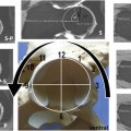
Fig. 10.1
MRI of the pelvis in an 8-month-old child with pyomyositis performed on a 1.5 T magnet with a cardiac coil. (a) Axial T2-FSE fs image through the lower pelvis demonstrates areas of poor fat suppression along the right thigh (white arrows). An area of confluent signal abnormality is clearly appreciated (black arrows) in the posterior soft tissues adjacent to the right ischium (black arrows). (b) Axial T1 fs image performed after intravenous contrast administration demonstrates abnormal enhancement in the same area, with a focal non-enhancing abscess (arrow)
Coils
A variety of imaging coils are useful for imaging the hip. Most imaging coils are multichannel, phased-array coils. Coil selection depends on many factors, including the manufacturer of the imaging system, patient age and size, shape of the body part imaged, and desired field of view (FOV). Image quality is highly dependent on proper coil selection. Proper coil selection requires that the clinician or radiologist determines prior to imaging whether one or both hips should be included in the FOV. While it is possible to change the coil at any point during an examination, this adjustment costs valuable imaging time. In general, in an otherwise healthy patient with acute pain in one hip, dedicated imaging of the hip in question (excluding the other hip) is preferred in order to achieve high-resolution images (Fig. 10.2). Regional coils, such as phased-array torso, cardiac, or body matrix coils, should be considered when imaging of the entire pelvis is indicated, at the expense of high-resolution imaging of a single hip. Localized surface coils allow for improved spatial resolution and better detail of the anatomic structures such as femoral head, joint capsule, cartilage, and labrum (Fig. 10.3). Larger body coils allow for increased SNR and more uniform signal intensity throughout the image, though with decreased spatial resolution [11]. One must consider whether the benefit of increasing the FOV to include the contralateral hip outweighs the loss of resolution that will accompany the increase in coverage (Fig. 10.4). In some instances it may be useful to image one patient using several coils, depending on the indication. In a patient with unilateral hip pain with systemic disease such as sickle cell disease (SCD), a dedicated surface coil positioned over the painful hip will provide high-quality images of the hip while a single, additional sequence with a larger, body matrix coil may provide important additional information about the surrounding pelvis and contralateral hip (Fig. 10.5). It is often worthwhile to obtain one coronal image through both hips with a body coil, which will serve as a guide for subsequent sequences, and also reveal whether there are bilateral or diffuse abnormalities [11]. Surface coils used for imaging of the hip joint and surrounding structures are flat or flexible so that they may be placed over the hip of interest. Some patients may not be able to hold still for extended periods of time, so it is often important to perform the most important imaging sequences early in an imaging protocol. Detailed clinical information about the patient’s symptoms is extremely helpful in establishing an appropriate protocol.
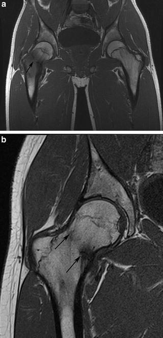
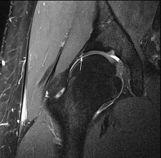
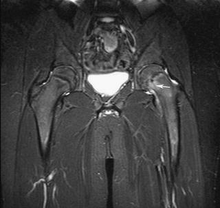
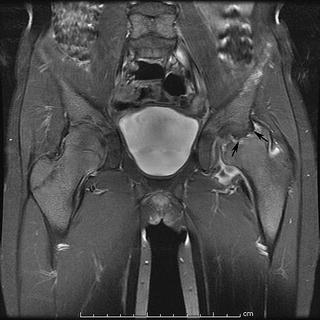
Fig. 10.2
Coronal T1-weighted images through the right hip in a 15-year-old male with femoral neck fracture. (a) Initial images performed with a large FOV through both hips using a body matrix coil demonstrate the fracture line (black arrow), but with poor spatial resolution. (b) A follow-up scan performed with a surface coil demonstrates the healing fracture (black arrows) with significantly improved spatial resolution. Both studies were performed on a 1.5 T magnet
Fig. 10.3
Coronal PD-FSE fs sequence through the right hip in a 17-year-old male using a small surface coil with a 15 cm FOV achieves high-resolution imaging of the intra-articular structures such that a superior labral tear (white arrow) is easily visualized
Fig. 10.4
Coronal STIR sequence on a 14-year-old male using a body matrix coil with a large 36 cm field of view. The mild left-sided slipped capital femoral epiphysis (arrow) and small associated left hip effusion are not well demonstrated given the large FOV
Fig. 10.5
Coronal T1 fs image after administration of intravenous contrast in a 9-year-old female with sickle cell anemia and avascular necrosis of the left hip (arrows). The large FOV was important for excluding disease on the contralateral hip
For single hip imaging, coronal images should extend through the entire joint. If the clinical indication is to evaluate for intra-articular pathology, coronal images through the iliopsoas anteriorly and sciatic nerve posteriorly are often sufficient [12]. In many cases the clinical history is not specific, or the pathology may be extra-articular, and it is therefore prudent to enlarge the FOV to include all of the muscle groups. Likewise, sagittal imaging through the joint may be limited to the greater trochanter laterally and the medial acetabular wall medially when the pathology is intra-articular, but more often imaging through the entire area is recommended to evaluate the adjacent soft tissues. When imaging through both hips is indicated, the coronal images are performed straight rather than oblique, and images extend through the anterior and posterior muscle groups on both sides. Likewise, axial images should include the soft tissues surrounding the hip, and should extend cranially and caudally to cover the area of clinical interest.
Sequences
MR protocols are highly driven by clinical history and should be tailored to the indication for imaging. Certain sequences will be selected based on their ability to demonstrate anatomic structures with high detail, whereas other sequences may have poorer resolution but may provide additional information regarding the presence of edema, hemorrhage, or even molecular structure. Imaging time is also an important factor, particularly in pediatric patients who may be under sedation or anesthesia, or who have limited ability to hold still if unsedated. The workhorse of musculoskeletal MR imaging is the spin-echo sequence, including T1-weighted, T2-weighted, and proton-density (PD)-weighted images. The relative contrast of the image will vary depending on the parameters of the particular imaging system. Spin-echo sequences have traditionally been performed as two-dimensional (2D) image acquisitions, though more recently three-dimensional (3D) spin-echo sequences have become available. The 3D sequences are volumetric acquisitions with isotropic voxel sizes allowing post-processing reformatting into any 2D imaging plane. This reformatting can be particularly helpful when imaging an obliquely oriented structure (such as the femoral neck) or a structure that is curved (such as the acetabular labrum).
Most multichannel phased-array coils allow for parallel imaging, which increases speed of imaging acquisition and thereby reduces imaging times. There are several types of parallel imaging techniques, including image-domain-based and k-space-based techniques [2]. Using either technique, each of the elements or channels in a phased-array coil provides separate image information which is combined with information from other elements to create an image. The advantage of parallel imaging is a reduction in overall imaging time, though with concomitant diminished SNR [2]. For this reason, common indications for applying parallel imaging techniques include high SNR sequence and/or those that require fast temporal resolution (such as contrast-enhanced dynamic imaging, breath-hold sequences, and volumetric acquisitions) [2].
Bone and Bone Marrow Sequences
Evaluation of bony contours is a critical piece of any musculoskeletal MRI examination, particularly in the hip where morphologic osseous abnormalities may contribute to hip pain and joint damage [13–16]. The “gold standard” for 3D bony imaging of the hip and pelvis remains multidetector computerized tomography (MDCT), as the significantly higher density of bony structures compared to the surrounding soft tissues allows for creation of beautiful 3D reconstructions. The images acquired with MDCT require the use of ionizing radiation directed at the pelvis, prompting clinicians and radiologists to answer as many clinical questions as possible using MRI in place of CT. At present it is generally not feasible to create 3D models of the proximal femur and/or pelvis from an MRI sequence (even a thin-section isotropic sequence) without rigorous and time-consuming segmentation techniques. The contrast between bone and soft tissues on MRI is significantly narrower than the vast contrast between these tissues at CT, which limits 3D volumetric modeling of MRI images. Rather than creating volumetric models of the bones, MRI is capable of evaluating structures in any imaging plane regardless of how the patient is positioned in the scanner. Images may be directly prescribed off of localizer sequences and acquired directly in a specific imaging plane, or they may be reformatted from an isotropic volumetric acquisition after the patient has left the scanner. One particular imaging technique that is useful for hip imaging is acquiring a rotating or “radial” plane of images. As both the femoral head and acetabulum are relatively spherical structures with curved surfaces, it is often helpful to rotate the imaging plane around the axis of either the femoral head or acetabulum, rather than acquiring contiguous parallel slices in any single plane. The most common indication for performing radial imaging of the hip is femoroacetabular impingement (FAI). By rotating the image along the axis of the femoral neck, cam lesions along the head/neck junction are easily detected and the extent of the deformity may be precisely mapped (Fig. 10.6). As an alternative to rotating the plane of imaging around the femoral neck axis, radial images may instead be oriented around the acetabulum to detect labral tears (this will be discussed in greater detail in the chapter on MR arthrography (MRA)). The improved SNR of a direct radial acquisition compared to a reformatted sequence from a thin, isotropic volumetric sequence is important for detection of subtle labral tears or cartilage lesions.
Fig. 10.6
Isotropic, thin-section sagittal oblique TrueFISP sequence through the right hip in a 34-year-old male with history of remote slipped capital femoral epiphysis, now with hip pain. (a) Radially oriented reformat rotating around the axis of the femoral neck was performed with 10° between images. (b) Anterosuperior image through the 11:00 position of the femoral head/neck junction demonstrates a prominent osseous bump (black arrow) and acetabular cartilage loss (white arrowhead). (c) Posterosuperior image at the 2:00 position demonstrates a bony bump (black arrow) and an acetabular rim cyst (white arrowhead)
MRI also provides an important assessment of intramedullary bone marrow signal. A variety of disease processes manifest with alterations in the normal or expected bone marrow signal, and detection of marrow signal changes is often an important clue to underlying pathology. No other imaging modality is capable of providing as much meaningful imaging information about the bone marrow as MRI. Although bone-seeking radiopharmaceutical studies in nuclear medicine indicate areas of increased bone turnover or increased blood supply [17], the findings are relatively nonspecific and precise anatomic information is lacking. In order to accurately assess the marrow with MRI, it is important to understand normal marrow structure, and how marrow changes over time. Bone marrow consists of osseous matrix (trabeculae), red marrow (cellular, hematopoietic), and yellow marrow (fatty, hematopoietically inactive marrow). Marrow composition changes with age, with conversion of hematopoietic marrow to fatty marrow in predictable patterns. T1-weighted spin-echo sequences are well suited for differentiating between red and yellow marrow, as well as for detecting pathologic marrow replacement processes. T1-weighted images are characterized by low TR (<1,000 ms) and low TE (<30 ms). Hematopoietic marrow tends to have intermediate signal on T1-weighted images, while yellow marrow has bright signal. Fluid-sensitive sequences with fat suppression are also useful in assessment of bone marrow, as fatty marrow signal is lower than surrounding muscle, in contrast to the isointense hematopoietic marrow. Pathologic marrow processes (leukemia, lymphoma, marrow edema, osteomyelitis, metastases, post-chemotherapy changes, etc.) demonstrate bright signal intensity on T2-weighted images and decreased signal on T1-weighted images [18]. In adult patients the bone marrow in the hip should largely consist of yellow, fatty marrow. Variable amounts of hematopoietic marrow will remain in the femoral neck and metaphyseal equivalents depending on age and hematopoietic demands. T1-weighted images allow the best determination of normal red-marrow patterns versus pathologic marrow signal, given that normal red marrow tends to have a patchy distribution [18] or flame-shaped pattern, versus the more amorphous or confluent pattern of other marrow replacement processes (Fig. 10.7). Pathologic marrow replacement processes do not respect boundaries such as the physeal scar of the proximal femur [19]. Pathologic marrow infiltrating lesions demonstrate dark signal on T1-weighted images relative to the surrounding marrow signal. These lesions are often more difficult to detect on T2-weighted images because of decreased contrast between normal and abnormal marrow. T1-weighted images also allow for assessment of fracture lines, which stand out from the surrounding bright, usually fatty marrow signal as a low-signal, linear signal abnormality (Fig. 10.2). T1-weighted images are also helpful in evaluation of bone or soft tissue lesions. Lesions containing fat, such as fat necrosis (Fig. 10.8), lipoma, or other fatty neoplasms, are best characterized by the bright signal on T1-weighted images that suppresses with fat-suppression techniques.
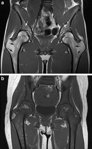
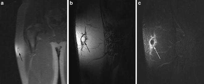
Fig. 10.7
(a) Coronal T1-weighted image through the pelvis and hips in a 17-year-old male with history of right hip pain reveals a normal marrow pattern, with predominantly fatty marrow with geographic or “flame-shaped” regions of residual hematopoietic marrow within the femoral metadiaphyseal region (black arrows) and superior acetabulum (white arrows). (b) The marrow is nearly completely replaced with intermediate signal intensity lesions on this T1-weighted image through the pelvis in an 8-year-old female with newly diagnosed leukemia
Fig. 10.8
Imaging of the right hip in a 15-year-old male with enlarging mass along the lateral aspect of the hip. (a) Initial GR localizer sequence through the right hip demonstrated a lesion confined to the superficial fat of the right upper thigh. A small surface coil (loop coil) was selected based on the superficial nature of the lesion. (b) T1-weighted image through the lesion demonstrated a multilobulated lesion within the subcutaneous fat which was isointense to the surrounding fat. (c) T1-weighted image with fat suppression after contrast demonstrated suppression of the signal within the lesion with peripheral enhancement. The diagnosis was fat necrosis and the patient improved with no further treatment
T1-weighted images are also performed after administration of the intravenous contrast agent gadolinium. The intrinsic T1-shortening effect of gadolinium allows tissues that take up gadolinium to appear brighter on T1-weighted images. The enhancement of such lesions is best appreciated by applying fat-suppression techniques so that the otherwise bright signal intensity of fat no longer is apparent. Gadolinium contrast is often administered to patients in whom there is concern for infection such as pelvic osteomyelitis or septic arthritis (Fig. 10.9), arthropathy, or neoplasm. Gadolinium is particularly useful for confirming that masses that have intrinsically bright signal on T2-weighted images are solid rather than complex cystic lesions (Fig. 10.10). It may be helpful to perform a T1-weighted sequence with fat suppression through a region of interest before the administration of gadolinium in order that the non-contrast image may later be subtracted (either mentally or with special software) from the post-contrast image. This is particularly helpful for lesions that often have intrinsically bright signal on T1-weighted images, such as hematoma or lymphatic malformation. The bright T1-signal in these lesions post-contrast may be mistaken for enhancement if pre-contrast imaging was not performed. Dynamic contrast-enhanced images are helpful for detection of perfusion abnormalities in the femoral head, such as in young patients with concern for Legg–Calvé–Perthes (LCP) disease [20], or differentiating transient synovitis from septic arthritis [21]. In order to perform multiple phases of imaging through the femoral heads in a short period of time, T1-weighted GR sequences are often performed in lieu of a spin-echo sequence. Both hips are imaged together in the coronal plane. Further investigation in this area is currently ongoing, as it has been postulated that the reperfusion pattern of the femoral head in patients with avascular necrosis (AVN) may be related to prognosis [20].
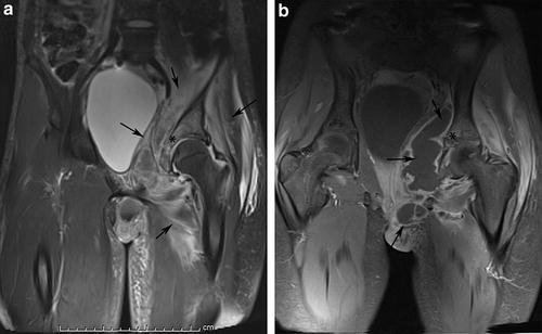
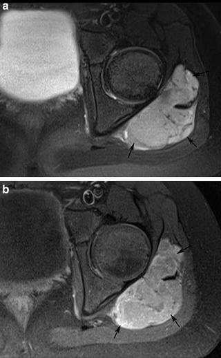
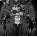
Fig. 10.9
Images through the hips and pelvis on a 3 T magnet in a 13-year-old female with fever, diffuse swelling, and pain surrounding the left hip and buttock. (a) Coronal T2-FSE fs image revealed abnormal bright marrow signal centered in the acetabulum around the tri-radiate cartilage (*) with a large amount of bright signal abnormality within the surrounding soft tissues (black arrows). (b) Coronal T1-weighted image with fat suppression after intravenous contrast demonstrates abnormal enhancement of the bone marrow (*) consistent with pelvic osteomyelitis, with a large, rim enhancing abscess (black arrows) within the pelvis and perineum. This required urgent surgical drainage
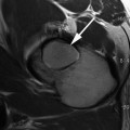
Fig. 10.10
(a) Axial T2-FSE fs image in a 9-year-old male with left hip pain demonstrated a well-marginated lesion within the gluteal muscles (black arrows) with internal septations and bright signal intensity, concerning for complex cystic lesion versus solid mass. (b) Axial T1-weighed image with fat suppression after the administration of intravenous contrast demonstrated relatively homogeneous enhancement of the solid mass, which was later confirmed to represent a synovial sarcoma
Fluid-Sensitive Sequences
Most disease processes (infection, traumatic fractures, malignancy, etc.) are associated with an increase in water content. This increased fluid content will contrast sharply with adjacent bony and soft tissue structures on sequences optimized to be fluid-sensitive. T2-weighted images are defined by both high TR (>2,000 ms) and high TE (>80 ms), which allow fluid signal to appear bright. Fat also appears bright on T2-weighted images and may mask underlying pathology. Ideally, a sequence designed to look for “pathology” should allow for markedly bright fluid signal and relatively diminished signal from all adjacent tissue structures, including fat. For this reason, it is common in musculoskeletal imaging to employ fat saturation with T2-weighted images. This increases the contrast between fat and nonfat containing tissues and also affects the overall dynamic range of the image [22]. This can be exceptionally helpful when evaluating patients with sports injuries and increases detection of subtle osseous or soft tissue lesions such as stress reaction or mild muscle strain (Fig. 10.11). The most common types of fat-suppression techniques include chemical fat suppression as well as short inversion time inversion-recovery (STIR) technique. Chemical fat suppression selectively diminishes the signal from fat with a spoiler sequence, without diminishing signal from other frequencies [18]. STIR sequences are performed in areas of magnetic field inhomogeneities that limit chemical fat-suppression techniques, but with a decrease in overall SNR. In STIR sequences, a 180° inversion pulse prior to spin-echo techniques negates the signal from fat but may also diminish signal from nearby frequencies [18]. The end result of both sequences is that the high signal from fat is removed, and the signal from water appears hyperintense [18]. Generally, most hip MR protocols rely on at least one fluid-sensitive image through the hip, often in the axial plane, and usually with fat suppression (Fig. 10.12). MR examinations performed to evaluate sports- or activity-related trauma or injury may require several planes of fluid-sensitive sequences, or a 3D volume acquisition that may be reformatted into multiple planes. This allows for optimal assessment of the bones and soft tissues for subtle edematous changes that may be missed if only a single imaging plane is performed.
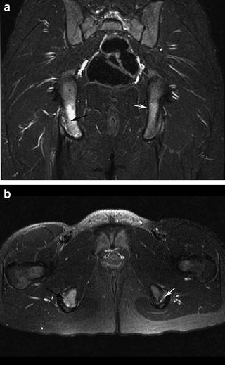
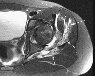
Fig. 10.11
Coronal STIR image (a) and axial T2-FSE with fs image (b) through the hips and pelvis in a 12-year-old female gymnast with hip pain reveals marrow edema within the right ischial tuberosity at the attachment site of the hamstring tendons (black arrows) consistent with avulsive stress injury. Subtle signal abnormality is also noted in the left ischial tuberosity (white arrows) on the left consistent with mild stress reaction
Fig. 10.12
Axial T2-FSE fs image through the left hip in an 11-year-old female with pain and inability to weight-bear after falling on her hip demonstrated a substantial amount of bright fluid in the surrounding musculature (white arrows) indicating edema and hemorrhage. There was a joint effusion which clearly demarcates the posterior labrum (black arrow) which had flipped between the femoral head and acetabulum
Cartilage Sequences
Assessment of the articular cartilage of the hip joint has become increasingly important, as advances in technology have enabled thin-section imaging through joints. Hip conditions such as developmental dysplasia of the hip (DDH) and FAI cause different patterns of cartilage damage within the hip joint [23]. Patients with cartilage damage related to DDH may be candidates for hip preserving procedures depending on the severity of the cartilage damage [24]. Patients with FAI may benefit from surgical intervention to relieve pain and return to activity [25]. Although cartilage contrasts with adjacent fluid on T2-weighted images, these sequences provide limited information about the cartilage other than its overall thickness. Likewise, the dark signal of fluid on T1-weighted image makes detection of cartilage lesions difficult given that there is little contrast between fluid and cartilage. For these reasons, other types of sequences are preferred for cartilage assessment.
Given the relatively thin cartilage surfaces in the hip, cartilage lesions are best appreciated at 3.0 T compared to 1.5 T in light of the increased SNR [26]. Patients with clinical concern for intra-articular pathology should be imaged at 3.0 T whenever feasible to optimally assess the cartilage integrity. Traditionally, non-contrast MRI with 2D fast spin-echo (FSE) sequences has been considered the workhorse sequences for cartilage imaging [27] in addition to 3D SPGR sequences [28] (Fig. 10.13). Intermediate-weighted (IM) FSE MRI sequences (TR 3,500–4,000, TE 30–35 ms) take advantage of the water content of the articular cartilage and demonstrate excellent contrast between articular cartilage and adjacent structures [29] (Fig. 10.14). The TE is slightly higher in IM-FSE sequences (TE 30–60) compared to PD-FSE sequences (TE 10–30 ms) in order to achieve a more optimal contrast between labrum, cartilage, and fluid [9, 20], thereby achieving the benefits of both PD- and T2-weighted images in one sequence. Articular cartilage is intermediate in signal on IM-FSE sequences, fluid is bright, and fibrocartilage is dark [29]. PD-FSE sequences with lower TE values are useful for assessing fibrocartilagenous structures, but are not as fluid-sensitive as IM-FSE sequences [9] (Fig. 10.15). In some reports, non-contrast FSE sequences demonstrate up to 87 % sensitivity and 94 % specificity in the detection of cartilage lesions [30]. Disadvantages of 2D FSE sequences include anisotropic voxels, slice gaps, and partial volume effects [22].
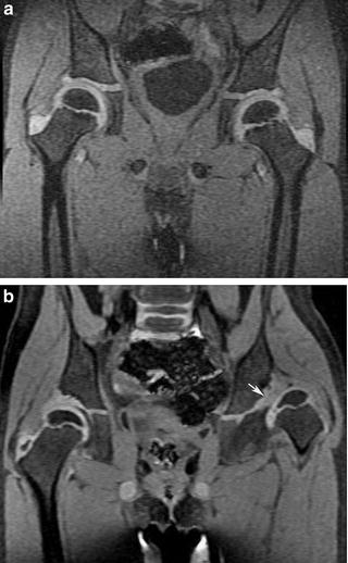
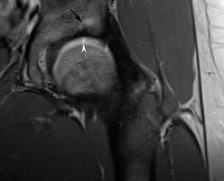
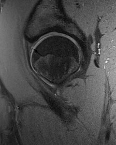
Fig. 10.13
(a) Coronal 3D SPGR image through the hips and pelvis of a 6-year-old male with hip pain revealed normal femoral head and acetabular cartilage. (b) Same sequence on a 5-year-old female with right-sided acetabular dysplasia revealed a shallow, irregular left acetabulum (white arrow) and aspherical left femoral head. Both studies were performed on a 1.5 T magnet with 1 mm slice thickness
Fig. 10.14
Coronal IM-FSE (TR 3,500, TE 28) sequence through the left hip on a 3 T magnet with a small surface coil in a 24-year-old woman with left hip pain demonstrated marrow edema within the anterosuperior acetabulum (black arrow) and bright fluid insinuating into a focal acetabular cartilage defect (white arrowhead)
Fig. 10.15
Sagittal PD-FSE (TR 2,730, TE 11) image with fat suppression through the left hip in a 16-year-old male with hip pain was performed on a 3 T magnet with a small surface coil and a small, 16 cm FOV. Both the acetabular and femoral head cartilage are well visualized, and an anterosuperior labral tear (black arrow) can be easily appreciated despite the non-arthrographic technique
There are a variety of different gradient echo (GR) sequences that are commonly utilized for imaging cartilage. GR sequences utilize excitation pulses with flip angles less than 90°. Image contrast is determined by the TR, TE, and flip angle. Spoiled gradient echo (SPGR) with fat suppression is the standard for morphologic imaging of cartilage [22


Related posts:

Stay updated, free articles. Join our Telegram channel
Full access? Get Clinical Tree
