, Gila Perk2, Natesa G. Pandian3, Hans-Joachim Nesser4 and Itzhak Kronzon2
(1)
Department of Cardiology, Cardiocentro Ticino, Lugano, Switzerland
(2)
Non-Invasive Cardiology, Lenox Hill Hospital, New York, NY, USA
(3)
Tufts University School of Medicine, Boston, MA, USA
(4)
Department of Medicine Elisabethinen, Teaching Hospital, Linz, Austria
Abstract
The presence of clinically significant paravalvular leak (PVL) that warrant repair ranges from 1 to 5% of patients with prosthetic valves and it is usually related to tissue friability, annular calcification, valve infection or technical factors. Surgical repair is the standard treatment for symptomatic PVL. Because of the increased risk of reoperation, there is tremendous interest in percutaneous closure of PVL. The accurate determination of the anatomical characteristics of the PVL (i.e. site, size and shape) is of paramount importance for proper selection of patients suitable for percutaneous closure, and the key for success of the procedure. 3D TEE appears to be the ideal technique for this purpose. In this chapter we will describe the normal 3D TEE appearance of mitral valve prostheses (both mechanical and biological), the 3D TEE imaging of mitral and aortic PVL, and, finally, the current role of 3D TEE during percutaneous PVL closure.
Electronic supplementary material
The online version of this chapter (doi:10.1007/978-1-4471-4745-9_8) contains supplementary material, which is available to authorized users.
Paravalvular leak (PVL) is a potential complication associated with surgical implantation of a prosthetic heart valve. The incidence of PVL is reported to be as high as 20 %, but this apparently high incidence is based on studies using transoesophageal echocardiography (TEE), which can detect even small, clinically insignificant paravalvular regurgitant jets. The presence of clinically significant PVLs that warrant repair is lower, ranging from 1–5 % of patients with prosthetic valves. PVL is usually related to tissue friability, annular calcification, valve infection, or technical factors. Earlier data showed that mitral PVLs occurred more often in the posterior two thirds of the annular ring, owing to a few different factors: (1) calcification of the mitral annulus is preferentially located in the posterior annulus, making this region less amenable to proper suturing; (2) the posterior ring is difficult to expose in the operating field, so suturing may be technically challenging; and (3) the circumflex artery runs adjacent to the posterior mitral ring, so surgeons may tend to suture this region more superficially. With increasing experience, however, PVLs in anterior locations have also been found to be common; in a recent review, PVLs in the 5–6 o’clock area were as prevalent as those in the 10–11 o’clock location.
When a PVL is large, it may result in volume overload and heart failure. Small PVLs usually remain asymptomatic. However, narrow, serpiginous channels or small multiple leaks may cause flow disruption (i.e., collision or abrupt acceleration and deceleration of flow stream), with an increase in shear stress on erythrocytes. This abnormal shear stress may lead to hemolysis and clinically significant anemia.
Currently, surgical repair is the standard treatment for symptomatic PVLs requiring intervention (as in patients with heart failure or persistent anemia requiring blood transfusion). This surgical intervention is associated with higher mortality (6–14 %) than the initial operation. Because of this increased risk, there is great interest in less invasive procedures.
Percutaneous closure of PVL was first attempted by Hourihan in 1992. Since then, percutaneous closure procedures using various devices and techniques have been reported in patients who were poor surgical candidates. Accurate determination of the anatomic characteristics of the PVL (i.e., site, size, and shape) is of paramount importance for proper selection of patients suitable for percutaneous closure and is key to the success of the procedure.
We believe that three-dimensional (3D) TEE is an ideal technique for this purpose. It can accurately assess the site, size, and shape of single or multiple PVLs, and the interventionist can observe the advancement of catheters towards the PVL in a 3D environment in real time. This chapter describes the normal 3D TEE appearance of mitral valve prostheses (both mechanical and biologic), the 3D TEE imaging of mitral and aortic PVL, and, finally, the current role of 3D TEE during percutaneous PVL closure.
8.1 Normal 3D TEE Appearance of Mitral Valve Prostheses
TEE has been considered the gold standard for assessment of mitral PVL. The transducer’s posterior position provides excellent visualization of the atrial side of a mitral prosthesis, while reverberation artifacts and acoustic shadowing cover the ventricular side. As soon as 3D TEE became commercially available, it was apparent that this new imaging technique provided much more “realistic” imaging of the atrial side of the prosthesis than the standard two-dimensional (2D) TEE.
In a normal mechanical, bileaflet prosthesis, the en face perspective allows for superb definition of two closed, semicircular discs in systole and three orifices (a small slit-like central orifice and two larger semicircular orifices) in diastole (Fig. 8.1a, b; Videos 8.1 and 8.2). In a biologic mitral prosthesis, the three leaflets can be visualized with exquisite finesse in diastole and in systole (Fig. 8.1c, d). Moreover, the suture ring is clearly depicted, firmly attached to the surrounding native annulus without any obvious dropout areas. Characteristically, stitches appear thicker than they actually are; the spatial resolution of the system is not adequate to show the two ends of a suture thread protruding from the knot, so they appear as a singular, thick bump. In Figure 8.1a, the arrow points at the image of one stitch.
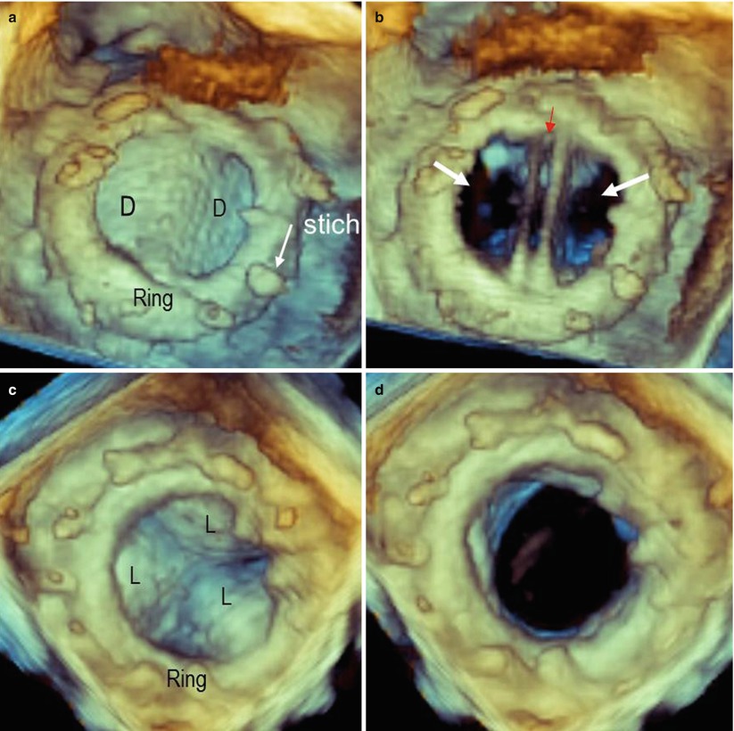
Fig. 8.1
(a, b) Three-dimensional image of a bileaflet mechanical prosthesis in en face perspective, in closed (a) and open (b) position. In panel a, the ring and stitches (arrow) are visible. In open position (b), the prosthesis shows three orifices: a small, slit-like central orifice between the two open discs (red arrow) and two large, lateral, semicircular orifices (white arrows). (c, d) Three-dimensional image of a biologic prosthesis in systole (c) and diastole (d). D disc, L leaflet
Because of the lack of major reverberations and shadowing with bioprosthetic valves, stents and leaflets of biologic prostheses can also be imaged from the ventricular perspective. Small changes in angulation and proper cropping may reveal fine details (Fig. 8.2).
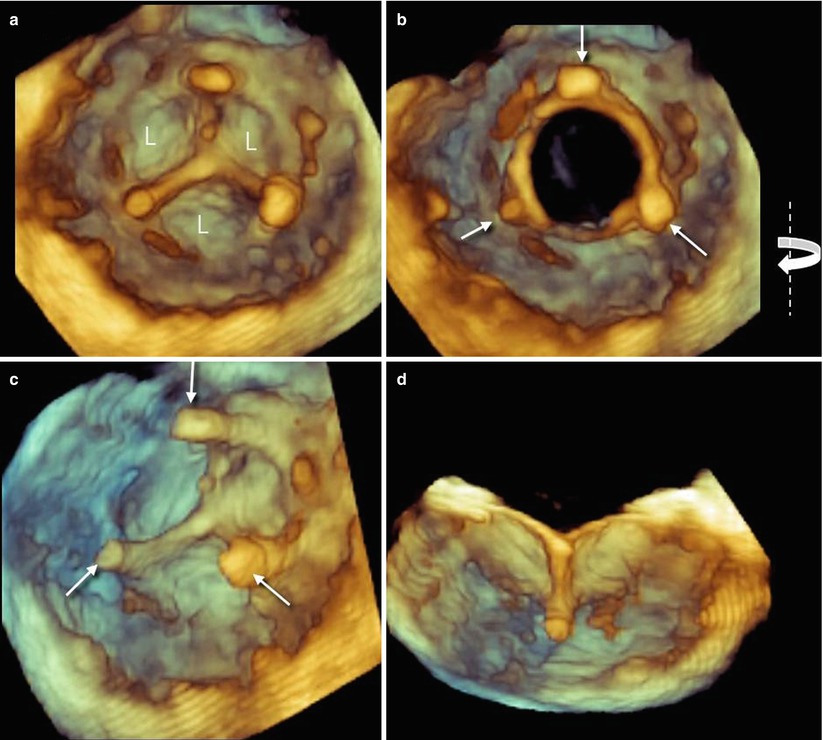
Fig. 8.2
(a, b) Three-dimensional image of leaflets (L) from ventricular perspective in closed (a) and open (b) position. Arrows point at stents supporting the leaflets. (c, d) Same images slightly rotated from right to left around the y-axis (curved arrow) and cropped in the middle (d). Both images show details of the prosthesis
Three-dimensional TEE color Doppler imaging of a mechanical prosthesis can show the diastolic laminar flow passing through the prosthetic orifice and covering the whole prosthetic area. During systole, small regurgitant jets can be seen around the occluders but always within the prosthetic ring. These regurgitant jets are called leakage backflow and occur with all types of mechanical valves. The leakage backflow is in fact inherent to the design of mechanical prostheses, and it provides a “washing” mechanism that limits thrombus formation on the atrial side of the prosthesis (Fig. 8.3).
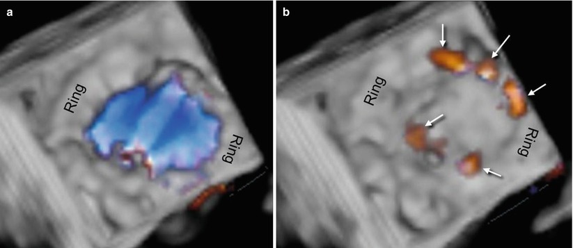
Fig. 8.3
(a) Three-dimensional TEE color Doppler image of a mechanical prosthesis, showing the laminar diastolic flow stream within the ring. (b) Several small regurgitant jets (leakage backflow) are seen around the hemidiscs (arrows)
8.2 Three-Dimensional TEE Imaging of PVLs
8.2.1 Mitral Prosthesis
The best imaging technique for diagnosis of mitral PVL is currently 2D TEE. A careful inspection of the entire annular circumference may reveal a dropout of echoes between the outer margin of the prosthetic ring and the native annular tissue. When color Doppler is applied, a regurgitant jet originating from the dropout confirms the diagnosis. The site of the defect can be defined using neighboring anatomic landmarks such as the atrial septum, aortic valve, or left atrial appendage. The severity of regurgitation can be assessed by adopting the same criteria used to define the severity of native valvular regurgitation.
The tomographic nature of 2D TEE makes it difficult to precisely define some anatomic characteristics of PVL, however, particularly the size and shape of the defect. Conversely, 3D TEE, which allows a “panoramic” view of the suture ring and discs from above, may show the exact number, sites, sizes, and shapes (circular, linear, crescent, or irregular) of PVLs. For standardization of communication, images should be presented in the “surgical view,” with the aortic valve at the top of the mitral ring (12 o’clock) and the left atrial appendage at approximately the 9 o’clock position. Thus, according to its location on this virtual clock, the location of any PVL may be reported as a single hour, if localized, or as a range of hours if the defect is larger or is crescent-shaped (Fig. 8.4a; Video 8.3). Although reverberations and shadowing may cover the ventricular aspect of mechanical prostheses, careful cropping aimed at eliminating reverberations may reveal the ventricular aspect of the PVL (Fig. 8.4b).
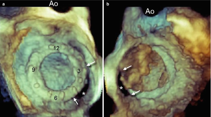
Fig. 8.4
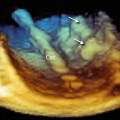
(a) Three-dimensional TEE image of a large paravalvular leak (PVL) (asterisk), as seen from the left atrial perspective and presented in the surgical view. A crescent-shaped configuration extending from 3 o’clock to 5 o’clock (arrows) can be seen. (b) Same volumetric data set from the ventricular perspective. The PVL can be seen (asterisk) after most of the reverberations and shadowing have been cropped. Arrows point at the margins of the leak. Ao aorta
In searching for and analyzing PVLs, the use of multiple perspectives and image orientations (not only the surgical view) is recommended. From above, the PVL can be hidden by protruding calcifications, which may cover the defect. In such a case, different perspectives may reveal the defect (Fig. 8.5). Three-dimensional color Doppler usually confirms the site of the defect (Fig. 8.6).
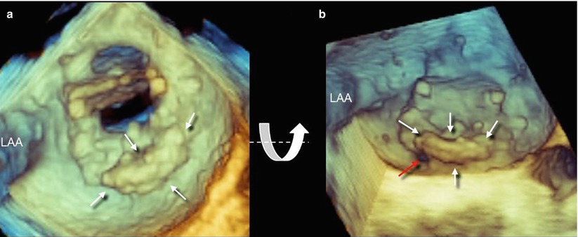
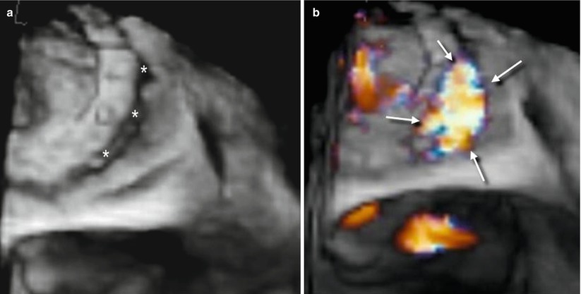
Fig. 8.5
(a) Three-dimensional TEE image of extensive calcification located from 3 o’clock to 6 o’clock (arrows). The PVL is not visible. A slight down-up rotation along the x-axis (curved arrow) reveals a small PVL located at 6 o’clock (red arrow). LAA left atrial appendage
Fig. 8.6
Three dimensional TEE image without (a) and with (b) color Doppler, showing a large PVL (asterisks) confirmed by a regurgitant jet (arrows)
Related posts:


Stay updated, free articles. Join our Telegram channel

Full access? Get Clinical Tree


