and Lori Ann Lewis1
(1)
Clinical Research Center of North Texas, Denton, TX, USA
Abstract
The most commonly studied regions of the skeleton remain to be the PA lumbar spine, proximal femur, and forearm in spite of the development of software applications that allow measurement of virtually any skeletal region. The manufacturers of DXA devices provide instructions for patient positioning for the different types of DXA studies that can be performed utilizing their device and software applications. While the manufacturer’s recommendations for positioning should always be given priority, an understanding of why certain aspects of positioning are recommended is useful. In particular, the technologist who understands the goals of positioning is better able to modify certain aspects of positioning when the patient’s anatomy demands it, without undermining the validity of the study. In reviewing the basic procedures and nuances of positioning for the three major scan types, the following discussion provides both the basic “how to” as well as the more detailed “why.”
The most commonly studied regions of the skeleton remain the PA lumbar spine, proximal femur, and forearm in spite of the development of software applications that allow measurement of virtually any skeletal region. The manufacturers of DXA devices provide instructions for patient positioning for the different types of DXA studies that can be performed utilizing their device and software applications. While the manufacturer’s recommendations for positioning should always be given priority, an understanding of why certain aspects of positioning are recommended is useful. In particular, the technologist who understands the goals of positioning is better able to modify certain aspects of positioning when the patient’s anatomy demands it, without undermining the validity of the study. In reviewing the basic procedures and nuances of positioning for the three major scan types, the following discussion provides both the basic “how to” as well as the more detailed “why.”
The PA Lumbar Spine Study
The classic goals of positioning during a PA lumbar spine study are a straight lumbar spine, clear separation between each vertebra, level iliac crests, and clearly visible ribs. This is ideal, but not all these attributes are always achievable within a single scan. To begin, ask the patient to lie on their back in the center of the table and to assume a position in which they feel straight. Then the technologist should attempt to palpate the top of the anterior–superior iliac crests on each side to determine if the crests are level. It is also advisable simply to look at the patient’s alignment on the table from both the head and foot of the table. It is not uncommon for the patient to say they feel straight when clearly they are not. They may also be straight in terms of their alignment from head to toe but lying at an angle on the scan table. If the patient appears straight and centered on the table, but the iliac crests are clearly unequal when palpated, it is recommended that the patient be asked to adjust their hips and lower abdomen to correct this. They should be asked not to move their head or shoulders but only their hips and to move them very slightly. Small corrections are generally all that is necessary. Then the patient’s legs should be elevated using the positioning block provided by the manufacturer. The purpose of elevating the legs is to flatten the lumbar spine against the table top and increase the separation between the lumbar vertebrae. The patient will also find this more comfortable. Once their legs have been positioned, the alignment of the patient on the table should be rechecked. Many positioning blocks are not square. One side will be longer than another. The orientation of the block can be altered between these two lengths depending on what is needed to flatten the lumbar spine. The angle of the thigh in relationship to the plane of the exam table can also be altered. The thighs may be virtually perpendicular to the table top or closer to 45°. The orientation of the block and approximate angle of the thighs should be noted and used for all subsequent PA lumbar spine studies. The patient should be asked to place their hands at their sides on the table pad. The patient’s head can be placed on a standard size pillow. Do not place the pillow under the shoulders. Instead it should be placed under only the head and neck so that the alignment of the thoracic spine in relationship to the exam table is not altered.
Once the scan has started, the technologist should watch the scan image closely during acquisition. On either side of the scan window, the iliac crests should be visible. Immediately, the technologist can recognize whether the crests are level. Although the lower lumbar spine may initially appear straight, as the scan progresses, the spine may lean in one direction or the other. In this case, the scan should be stopped and the patient repositioned by adjusting the shoulder and/or pelvis position so that the entire lumbar spine will be straight. This is may also be seen in scoliosis, but in scoliosis, the spine curves sideways. The situation described here refers to a spine that is inherently straight but which is leaning to one side or the other, much like the Leaning Tower of Pisa. The PA spine study in Fig. 4-1a–c is an example of this. In Fig. 4-1a, the spine is clearly leaning to one side. As shown in Fig. 4-1b, this resulted in the necessity of rotating the disc space markers. Adjustment of the pelvis resulted in a straight spine and unrotated disc space markers, as shown in Fig. 4-1c. In terms of the accuracy and precision of the scan, the most important criterion is that the spine is straight. Level iliac crests are ultimately not important, if the spine is straight. The scan should include at least half of S1 and half of T12. However, the scan should always contain ribs. Because the lowest set of ribs may actually be on T11 instead of T12, the scan may need to contain at least half of T11. Visualizing S1 and the lowest set of ribs ensures that all of L1 and L4 and their contiguous disc spaces are included in the scan, which is necessary for proper analysis. It also aids in proper labeling of the vertebrae.1
Fig. 4-1.
(a) This PA lumbar spine study illustrates the appearance of a leaning spine. The tops of the iliac crests are unequal, which suggests that the spine could be straightened by adjusting the patient’s hip position. (b) This is the PA lumbar spine study shown in Fig. 4.1a. Because the spine is leaning, the disc space markers at L3–L4 and L4–L5 had to be rotated. This will result in poorer precision. (c) This is the same patient as shown in Figs. 4.1a and b, but now the hip position has been adjusted, resulting in a straight spine and horizontal disc space markers at all levels.
The Effect of Vertebral Rotation
Rotation of the vertebral bodies may be a component of idiopathic scoliosis and adult-onset degenerative scoliosis. As noted previously in Chap. 3, in studies done to assess the effect of vertebral body rotation on bone density measured in the lumbar spine with DXA [1], vertebral segment area increased with increasing rotation up to 50° in either direction from midline and then decreased between 50° and 60°. The BMC remained relatively constant throughout rotation except at the extreme of 60° on either side of the midline at which point it decreased. Thus, increasing area with rotation resulted in BMD decreasing with rotation to either side of the midline as much as 20 %. In clinical practice then, rotation of the spine for any reason should be expected to cause an apparent decrease in bone density when measured with DXA.
Patients with lumbar scoliosis will not have a straight spine by definition, no matter how good the technologist’s positioning skills. In addition, rotation of the vertebrae often accompanies scoliosis. This is termed rotoscoliosis. This rotation cannot be corrected by the technologist, but it should be noted because it will affect the measured BMD. Rotation is perhaps most easily signaled on the bone density study by the lack of alignment of the spinous processes as shown in Fig. 4-2a, b. Patients with severe thoracic kyphosis may not flatten out the lumbar spine with elevation of the legs to any degree which may reduce vertebral separation, making placement of the disc space markers uncertain. Patients with disc space collapse and arthritic changes in the spine may also not show clear vertebral separation with any degree of leg elevation. These are simply anatomic limitations that the technologist cannot overcome with even the most expert positioning skills.
Fig. 4-2.
(a) Rotation of the vertebrae should be suspected from this image. The spinous processes are not aligned in this PA lumbar spine study. This cannot be corrected by the technologist. (b) This is the same PA lumbar spine study as shown in Fig. 4-2a. The spinous processes have been marked to emphasize the lack of alignment and suggested rotation of the vertebrae, particularly in the lower lumbar spine.
The Proximal Femur Study
The first decision to be made when the proximal femur is to be scanned is to decide whether the right or left proximal femur will be studied. This assumes, of course, that the technologist has not been instructed to perform a bilateral femur study, in which both proximal femurs would be measured. When DXA devices became clinically available in 1988, by default, the right femur was scanned unless the technologist deliberately altered the machine settings in order to perform a left proximal femur study. There was no compelling scientific reason for the default choice of the right proximal femur. At some point in time, the left proximal femur became the default selection. Again, the reason was not because of some medical or scientific finding. The choice of the left femur simply reflected the design of DXA scan tables, in which the left proximal femur of the patient was more easily accessible than the right proximal femur. Leg dominance, from a functional perspective, is not a reason to select either femur because differences in bone density are not expected on that basis alone. However, if the patient has a prior hip fracture or is known to have orthopedic hardware on one side, the unaffected proximal femur, regardless of actual side, should be studied. If the patient is known or suspected of having scoliosis, the authors recommend scanning the proximal femur on the side of the convexity.
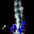
The ultimate goals of positioning a patient for a proximal femur study are a properly rotated proximal femur and straight femoral shaft. When the patient lies supine on the scan table, normal femoral anatomy results in a femoral neck that is angulated or anteverted when compared to the plane of the exam table. This is undesirable from the standpoint of the DXA study in which the femoral neck should ideally be parallel to the plane of the exam table. To bring the femoral neck into a position in which it is parallel to the table surface, the proximal femur must be rotated internally. How much to rotate any one individual’s proximal femur to make the femoral neck exactly parallel to the scan table is impossible for the technologist to determine in advance. Most manufacturer-supplied proximal femur positioning devices result in an internal rotation of approximately 20°. The best visual indication of the rotation of the proximal femur is the size of the lesser trochanter in the proximal femur scan image. Unfortunately, there is not anything that the technologist can see prior to starting the scan that ensures sufficient rotation. Because the lesser trochanter is a posterior structure and the scan image is acquired in the PA direction, insufficient internal rotation results in a very large appearing lesser trochanter. In honor of the first ISCD technologist certification course which was held in Colorado Springs, CO, this has been called the “Pike’s Peak” sign. Figure 4-3a is the image of a proximal femur from a study in which the leg was inadequately rotated, resulting in a very large lesser trochanter. With increasing internal rotation, the lesser trochanter decreases in size and can disappear altogether. It is desirable to see a small amount of the lesser trochanter, as on subsequent studies, this is the only visual clue to how successfully the internal rotation has been replicated. If the rotation is not replicated, the measured BMD can change on this basis alone. The size of the lesser trochanter in the DXA proximal femur image in Fig. 4-3b indicates sufficient internal rotation. Although this would be undesirable in a baseline study of the proximal femur, follow-up studies using the proximal femur in this patient should be done with this same degree of rotation.
Fig. 4-3.
(a) This proximal femur study illustrates the very large lesser trochanter that results from inadequate internal rotation of the proximal femur. (b) In this proximal femur study, the appearance of the lesser trochanter suggests appropriate internal rotation of the proximal femur.
When only one proximal femur is scanned, it is recommended that the shaft of the femur is straight. Generally, when the patient initially lies on the table, the femur is abducted or moved outward from the center line. It will thus need to be adducted or moved back toward the center line. If the femoral shaft is abducted when the patient lies down, it will need to be adducted slightly. Only experience in visualizing the proximal femur within the leg and its relationship to the position of the patella allows the technologist to move the proximal femoral shaft to the correct alignment. The sides of the femoral shaft are not parallel. They tend to taper inward from the proximal region down to the mid-region of the shaft.2 Therefore, it is an imaginary line that bisects the femoral shaft that should be parallel to the edge of the scan table, not the lateral edge of the femoral shaft itself. Once again, the technologist cannot know with certainty whether this positioning goal has been achieved until the image appears on the computer screen during scan acquisition. The alignment must often be adjusted based on the initial appearance of the shaft in the first few lines of the image. Figure 4-4 illustrates a proximal femur study in which the femoral shaft was not straight or parallel to the edge of the table. This proximal femur is still abducted. The positioning should be corrected by moving the leg slightly toward the center of the table. The need to adjust the position of the femoral shaft based on the scan image should not be viewed as a failure on the part of the technologist. The only failure would be not correcting the alignment when the imaginary line bisecting the femoral shaft is clearly not parallel to the edge of the scan table.
Fig. 4-4.
The shaft of the proximal femur is clearly angled in this study. The leg should be adducted such that a line that bisects the femoral shaft is parallel to the edge of the scan table.
Several positioning devices are available and are usually provided by the manufacturer of the specific device. In the authors’ experience, it is generally preferable to ask the patient to leave their shoes on, as the fixation of the foot at a specific angle seems to be easier. The patient should be asked to lie down and center themselves on the scan table, although it is not imperative that they be exactly centered. With the technologist standing at the foot of the table, they are then asked to point the toes of the leg to be scanned toward their head and then roll the foot inward until they feel the slanted surface of the positioning device being used. Once that is done, the foot is strapped into place. They are then immediately asked to relax the leg and foot and allow the straps to hold the foot in place. It is imperative that they relax the leg to avoid a leg cramp. The patient is asked to point their toes toward their head, because this tends to result in the entire leg being rotated, rather than just the lower leg. After the foot is positioned within the device, the technologist then tells the patient that she is going to lift and move their leg slightly and asks the patient to try not to help him or her do so. The impulse to assist is one that most patients need to be told to overcome. The technologist then abducts or adducts the leg as necessary, making an educated guess as to where the leg needs to be. Again, the final determination of whether the shaft is straight is based on the scan image during acquisition.
When using a manufacturer’s positioning device with a fixed angle, it may become clear during scan acquisition that insufficient internal rotation has been achieved. Assuming that this is not the result of inadequate positioning or an alteration of positioning by the patient, the technologist has two choices. The first is to proceed with the scan, realizing that the femoral neck BMD would almost certainly be lower if additional internal rotation was achieved. The second choice is to abandon the use of the positioning device and utilize the “cross-ankle” technique. In this positioning technique, the leg to be studied is manually rotated internally. While holding the leg in internal rotation, the technologist asks the patient to place the leg not being scanned across the chosen leg at the ankle. This cross-ankle technique should be noted in the patient’s chart as being necessary to achieve the desired degree of internal rotation. The position of the patient’s feet when using the cross-ankle technique versus the standard positioning device is shown in Fig. 4-5a–d. Some patients may not be able to do this, because it may place painful stress on the hip joint of the leg that is not being scanned. Recall that the appearance of the lesser trochanter on the scan image is the only way to visually assess the magnitude of the internal rotation, whether using the manufacturer’s positioning device or the cross-ankle technique, and it is the baseline rotation that must be replicated during subsequent studies.
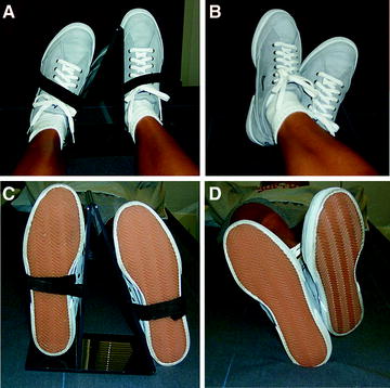
Fig. 4-5.
(a) This is the view from the head of the scan table of a patient’s feet in the GE Lunar positioning device for a single proximal femur study. (b) This is the view from the head of the table of a patient’s feet positioning for a single proximal femur study using the cross-ankle technique. (c) This is the view from the foot of the scan table of a patient’s feet in the GE Lunar positioning device for a single proximal femur study. (d) This is the view from the foot of the table of a patient’s feet positioning for a single proximal femur study using the cross-ankle technique.
If the cross-ankle technique is used for a baseline proximal femur study, the cross-ankle technique should also be used for follow-up studies on that patient. Additionally, if this technique is to be used at a facility, a proximal femur precision study should be performed in which the cross-ankle technique is utilized.
The Effect of Proximal Femoral Rotation
Related posts:

Stay updated, free articles. Join our Telegram channel

Full access? Get Clinical Tree


