elements in the x-direction and  elements in the y-direction. The lengths of the element are
  in the x– and y-directions, respectively and the corresponding gap widths in those directions are
  . The geometry for one of those elements is shown in Fig. 7.1. We can use the multiple point source model developed in Chap. 6 (see Eq. (6.33)) to represent each element. The pressure wave field of the entire array can then be written as
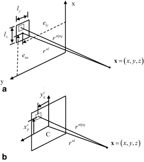
Fig. 7.1
a Geometry parameters for an element of a 2-D array radiating into a fluid, and b details of the element segment parameters within each element

(7.1)
where  are the apodization constants in the x– and y-directions, respectively, and
  are the time delays and where
  is the normalized pressure,
  , of a single element in the multiple point source model of Eq. (6.33) as implemented in the MATLAB® function ps_3Dv (Code Listing C.20), that is,
 are the apodization constants in the x– and y-directions, respectively, and
  are the time delays and where
  is the normalized pressure,
  , of a single element in the multiple point source model of Eq. (6.33) as implemented in the MATLAB® function ps_3Dv (Code Listing C.20), that is,
(7.2)
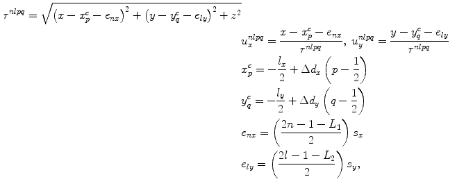
The various parameters appearing in Eq. (7.2) are:
(7.3)
where  are the lengths of the element segments in the x– and y-directions, respectively, and
  are the array pitches in the x– and y-directions.
 are the lengths of the element segments in the x– and y-directions, respectively, and
  are the array pitches in the x– and y-directions.
The model for a contact array radiating P-waves into an elastic solid is very similar to the fluid case. If we compare the original Rayleigh-Sommerfeld model of Eq. (6.21) with the corresponding contact model of Eq. (6.38) or, equivalently, the far field models of Eqs. (6.26) and (6.41) we see that we can get the contact case from the fluid case by making the replacement  to go from a model of a pressure field to one for a velocity field, and including an extra term
  to account for the additional directivity and polarization terms present in the velocity field for the contact case. However, since the segments are typically very small we can approximate this additional term by its value at the centroid of each segment, in which case
  and
and  , where
 to go from a model of a pressure field to one for a velocity field, and including an extra term
  to account for the additional directivity and polarization terms present in the velocity field for the contact case. However, since the segments are typically very small we can approximate this additional term by its value at the centroid of each segment, in which case
  and
and  , where
(7.4)
and (see Eqs. (6.39) and (6.40))

(7.5)
and, recall,  is the ratio of the compressional and shear wave speeds in the solid. Making these changes to Eq. (7.2), our model for the contact array gives the velocity field in the solid as
 is the ratio of the compressional and shear wave speeds in the solid. Making these changes to Eq. (7.2), our model for the contact array gives the velocity field in the solid as
(7.6)
with

(7.7)
Generally, we would expect that both  and
and  will also vary very slowly over the element, so if we approximate those parameters by their values at the centroid C of the element (see Fig. 7.1), we can write Eq. (7.6) instead as
 and
and  will also vary very slowly over the element, so if we approximate those parameters by their values at the centroid C of the element (see Fig. 7.1), we can write Eq. (7.6) instead as
(7.8)
where  and
and
 and
and
(7.9)
which then can also be simply rewritten in terms of the normalized pressure as

(7.10)
If the element itself is less than a wavelength in length in both the x– and y-directions then we expect that we can use a single point source model for each element. In this case, the single point source model for the array gives

(7.11)
for the immersion case, and

(7.12)
for the contact case. These are simply special cases of Eqs. (7.2) and (7.10), respectively, for these small element sizes. For the immersion case, Eq. (7.11) is implemented automatically by the MATLAB® function ps3Dv when both element lengths are less than a wavelength, as discussed in Chap. 6. One could also use a single point source model for larger elements by specifying  when evaluating the normalized pressure with ps_3Dv but this must be done with care since a single point source model will lose accuracy as the element size increases unless one is computing fields sufficiently far from the element so that one is in the far field of the element.
 when evaluating the normalized pressure with ps_3Dv but this must be done with care since a single point source model will lose accuracy as the element size increases unless one is computing fields sufficiently far from the element so that one is in the far field of the element.
7.1.1 Far Field Behavior of an Array
We can certainly use the single point source models to examine the wave field of the array when we are in the far field of the entire array . In this case, we can approximate  as (see Fig. 7.2)
 as (see Fig. 7.2)
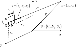
Fig. 7.2
Parameters for defining the behavior of an array element in the far field

(7.13)
where

(7.14)
If we consider the immersion case, Eq. (7.11), we then have
![$$ \begin{aligned} p( \mathbf{x},\omega)=\frac{\rho c{{v}_{0}}( \omega)}{2\text{ }\!\!\pi\!\!\text{ }}\sum\limits_{n=1}^{{{L}_{1}}}{\sum\limits_{l=1}^{{{L}_{2}}}{{{{\tilde{C}}}_{n}}{{{\tilde{C}}}_{l}}}}\exp ( \text{i}\omega \Delta {{t}_{nl}} )({-}\text{i}k{{l}_{x}}{{l}_{y}} ) \\& {{D}_{\text{e}}}( k{{U}_{x}}{{l}_{x}},k{{U}_{y}}{{l}_{y}} )\frac{\exp ( \text{i}kR )}{R}\exp [{-}\text{i}k( {{e}_{nx}}{{U}_{x}}+{{e}_{ly}}{{U}_{y}} ) ],\end{aligned} $$](/wp-content/uploads/2016/05/A314073_1_En_7_Chapter_Equ15.gif)
(7.15)
where  is the element directivity, given by
 is the element directivity, given by
(7.16)
![$$p\left( \mathbf{x},\omega \right)=\frac{\rho c{{v}_{0}}\left( \omega \right)}{2\pi }\left( -\text{i}k{{L}_{1}}{{l}_{x}}{{L}_{2}}{{l}_{y}}\right){{D}_{\text{e}}}\frac{\sin \left[ \left( {{L}_{1}}k{{s}_{x}}{{U}_{x}} \right)/2 \right]}{{{L}_{1}}\sin \left[ \left( k{{s}_{x}}{{U}_{x}}\right)/2 \right]}\frac{\sin \left[ \left( {{L}_{2}}k{{s}_{y}}{{U}_{y}} \right)/2 \right]}{{{L}_{2}}\sin \left[ \left( k{{s}_{y}}{{U}_{y}} \right)/2\right]}\frac{\exp \left( \text{i}kR \right)}{R},$$](/wp-content/uploads/2016/05/A314073_1_En_7_Chapter_Equ17.gif)
(7.17)
If we set the amplitude weights and time delays equal to zero, then as shown in Chap. 4 we can sum the remaining series to find
![$$ p( \mathbf{x},\omega)=\frac{\rho c{{v}_{0}}( \omega)}{2\pi }({-}\text{i}k{{L}_{1}}{{l}_{x}}{{L}_{2}}{{l}_{y}} ){{D}_{\text{e}}}\frac{\sin [ ( {{L}_{1}}k{{s}_{x}}{{U}_{x}} )/2 ]}{{{L}_{1}}\sin [ ( k{{s}_{x}}{{U}_{x}} )/2 ]}\frac{\sin [ ( {{L}_{2}}k{{s}_{y}}{{U}_{y}} )/2 ]}{{{L}_{2}}\sin [ ( k{{s}_{y}}{{U}_{y}} )/2 ]}\frac{\exp ( \text{i}kR )}{R}, $$](/wp-content/uploads/2016/05/A314073_1_En_7_Chapter_Equ18.gif)
(7.18)
which shows that, as in the 2-D case, in the far field of the entire array we see both the element directivity,  , and directivity,
  , associated with an array of point sources [1], where the point source directivity is
 , and directivity,
  , associated with an array of point sources [1], where the point source directivity is
 ![$$ {{D}_{\text{s}}}( k{{s}_{x}}{{U}_{x}},\ k{{s}_{y}}{{U}_{y}} )=\frac{\sin [ ( {{L}_{1}}k{{s}_{x}}{{U}_{x}} )/2 ]}{{{L}_{1}}\sin [ ( k{{s}_{x}}{{U}_{x}} )/2 ]}\frac{\sin [ ( {{L}_{2}}k{{s}_{y}}{{U}_{y}} )/2 ]}{{{L}_{2}}\sin [ ( k{{s}_{y}}{{U}_{y}} )/2 ]}. $$](/wp-content/uploads/2016/05/A314073_1_En_7_Chapter_Equ19.gif)
(7.19)
Figure 7.3 shows the element directivity of a square element where the pitch is either one wavelength or two wavelengths. We see, as in the 2-D case, a very broad radiation pattern at the one wavelength case and that this radiation becomes more concentrated for the two wavelengths pitch. In the case of a linear array element, one dimension will typically have a length of several wavelengths or less while the other length will be many wavelengths. Figure 7.4 shows a contour plot of the far field directivity (looking down the z-axis) for an element where the length is two wavelengths in the x-direction and 15 wavelengths in the y-direction. As can be seen from that figure, the beam radiation is tightly confined in the y-direction but much broader in the x-direction, as expected.
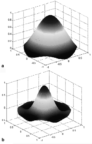
Fig. 7.3
The far field directivity of a square element when a the length of the element is one wavelength, and b when the length of the element is two wavelengths
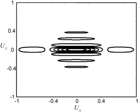
Fig. 7.4
Contour plot of the far field directivity of a linear array element, in a plane perpendicular to the z-axis, where the length of the element is two wavelengths in the x-direction and 15 wavelengths in the y-direction. The x– and y-coordinates of the plot are the unit vector components 

7.1.2 Beam Steering in 3-D
In Chaps. 3–5, we showed for 2-D problems that beam steering could be generated by applying a spatially linear time delay to the face of a transducer or an array. In the next chapter, the corresponding steering time delays for 2-D arrays radiating a 3-D wave field are obtained, where it is shown that to steer a 2-D array (with pitch and
and  elements in the x-direction and pitch
  and
and  elements in the y-direction) in a single medium in a direction defined by the spherical coordinates
  (see Fig. 7.5


 and
and  elements in the x-direction and pitch
  and
and  elements in the y-direction) in a single medium in a direction defined by the spherical coordinates
  (see Fig. 7.5
Stay updated, free articles. Join our Telegram channel

Full access? Get Clinical Tree


