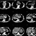
Fig. 1.1
An example from the mid-1980s of a simultaneous emission and transmission scan acquired with a gamma camera in a subject with a locally advanced cancer of the base of the tongue, intended for treatment with catheter-directed intra-arterial chemotherapy. The low-resolution anatomical image is produced using a Gd-153 external radionuclide source. Gd-153 has two γ-photons of energies 97 and 103 keV and thus is readily separated by pulse height discrimination from Tc-99 m (140 keV). The image shows an example of intra-arterially administered [99mTc]-MAA (‘radionuclide distribution’ in lower right corner) and the reconstruction from the Gd-153 transmission source (‘attenuation scan’ bottom left) in the sagittal plane. The fused image is shown in the top right corner and a reference image, a transaxial section, in top left corner. The red arrow on the fused image shows the approximate location of the tumour, indicating that the current location of the catheter needed to be revised for better tumour targeting (For further information, see Ref. [5])
For further discussion about these systems, the reader is referred to the review article by Bailey [6]. This technology found extensive use in SPECT myocardial perfusion imaging for correcting for photon attenuation and has been incorporated into imaging guidelines issued by professional organisations [7].
However, even while these developments were being implemented, others were starting to explore the use of CT with SPECT. Moore used a CT scan as the ‘true’ density distribution for attenuation correction in the early 1980s [8], and Fleming showed how a CT scan could be used in an iterative algorithm to produce quantitative SPECT reconstructions [9]. Hasegawa led a group in the early 1990s that sought to integrate many of these developments by producing a single detector that could record the X-rays from a CT source as well as the γ-photons emitted by an in vivo radiopharmaceutical [10]. The original detector was made from high purity germanium, but they explored other detectors at a later stage [11]. In addition, the same group combined a diagnostic CT scanner with a conventional gamma camera [12] using standard detectors. The combined clinical scanners shared a common patient table for sequential SPECT and CT imaging. In the late 1990s a combined gamma camera and X-ray CT system became commercially available based on a low-beam current (1.0–2.5 mA) X-ray tube (GE Discovery VG Hawkeye) [13]. Having demonstrated the benefits of combined multimodal SPECT/CT imaging on this platform, which was enormously successful commercially, other groups and vendors explored the added value of integrating a fully capable diagnostic CT scanner with dual-head SPECT gamma cameras (e.g. see [14]).
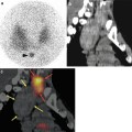
Today, combined SPECT and CT scanners are available in a variety of configurations with different CT scanner performance from flat-panel detectors using cone-beam CT geometry, originally developed for on-board imaging on radiotherapy LINACs, to high-end conventional fast multi-detector (e.g. 2, 4, 6, 16, and 64 slice) systems. Figure 1.2 shows a recent clinical example from such a device.
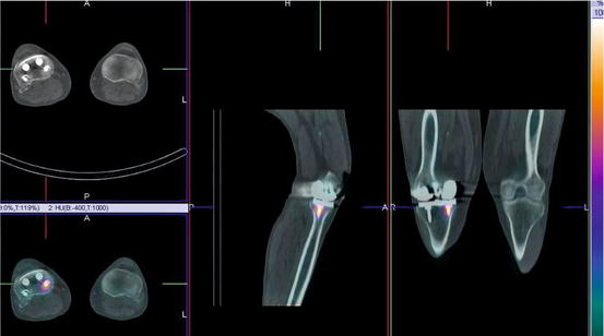
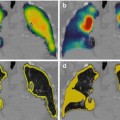
Fig. 1.2
An example from a contemporary SPECT/CT system demonstrating focally increased uptake on a 99mTc bone scan around an orthopaedic screw 3 years after knee replacement. The potential causes include infection and loosening or bony reaction to the screw
1.3 Radiation and Interaction with Matter
The ability to produce cross-sectional images of the human body, whether using an external source of X-ray photons or from an internal source of γ-photons, utilises radiation that can penetrate the body’s tissues. Radiation can be divided into particulate radiation, such as alpha, beta, and positron, or electromagnetic radiation, that is, massless quantised energy. Examples of different types of electromagnetic radiation that the reader would be more familiar with include radio waves, visible light, infrared radiation (heat), and microwaves as well as the high-energy radiations which can cause ionisation of atoms such as X-rays, γ-rays, and cosmic (γ) radiation. Table 1.1 lists some properties of some of the ionising radiation encountered in nuclear medicine.
Table 1.1
Types of radiation and properties used in nuclear medicine imaging and therapy
Type of radiation | Symbol | Mass (kg) | Origin | Typical energy (MeV) |
|---|---|---|---|---|
Alpha | α2+ | 6.64 × 10⁻²⁷ | Nucleus | >2 |
Beta | β− | 9.11 × 10⁻³¹ | Nucleus | 0.2–4.0+ |
Positron | β+ | 9.11 × 10⁻³¹ | Nucleus | 0.2–4.0+ |
X-ray | X | 0 | Electron shells | 0.04–0.10 |
Gamma | γ | 0 | Nucleus | 0.05–0.5 |
Annihilation | γ± | 0 | Outside atom | 0.511 |
Bremsstrahlung | – | 0 | Outside atom | 0.2–4.0+ |
Auger | – | 9.11 × 10⁻³¹ | Electron shells | <0.05 |
In general, nuclear medicine utilises γ radiation to form images with a gamma camera, annihilation radiation emitted after positron-electron annihilation with a PET camera, X-rays to measure tissue density using a CT scanner, and alpha or beta radiation for radionuclide therapy. A further secondary form of radiation, bremsstrahlung, is produced as an electron path deviates due to the influence of a nearby charged particle (usually the nucleus of an atom). From classical physics we know that any force acting on a charged particle causing acceleration will result in radiation being produced. As an electron, in an X-ray tube or produced as a result of β− decay, passes through matter, it will experience many deviations and collisions resulting in a continuous spectrum of radiation being emitted, the bremsstrahlung, literally ‘braking radiation’ in German. Superimposed onto this continuous spectrum is the characteristic radiation emitted when electrons drop down from outer shells to fill the vacancies caused by ionisation, resulting in a polychromatic spectrum of energies (Fig. 1.3) as opposed to the monochromatic radiation seen with most γ-emitters used in nuclear medicine imaging.
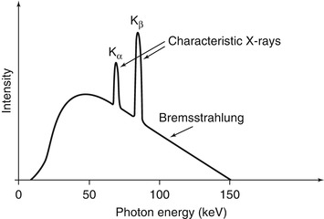
Fig. 1.3
A hypothetical X-ray spectrum is shown illustrating the polychromatic nature of the photons produced by the continuum of bremsstrahlung radiation superimposed with the characteristic radiation corresponding to different transitions within the electron shells
Electromagnetic radiation interacts with matter by three principal mechanisms: the photoelectric effect, Compton scattering, and pair production. The photoelectric effect is the predominant mechanism by which X-rays interact with matter, and for the γ-ray energies used in nuclear medicine, the predominant mode of interaction is Compton scattering. This distinction has implications when using X-ray CT data in SPECT attenuation correction algorithms as the absorption profile is different.
X-rays, being in general of lower photon energy than γ-rays, tend to be totally absorbed by the photoelectric interaction with inner shell orbital electrons in the tissues of the body. The higher energy γ-rays are more likely to interact with a weakly bound outer shell electron in a Compton interaction whereby they lose some energy in the elastic scattering and change direction. The two effects are illustrated in Fig. 1.4.
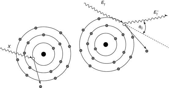
Fig. 1.4
The photoelectric effect (left) is where an incident photon (X) displaces an inner shell electron thereby leaving a vacancy and ionising the atom. X-rays and Auger electrons may be produced after as the vacancy is filled by an outer shell electron. Compton scattering (right) is more probable at higher photon energies. The incoming photon (E γ) elastically scatters off a weakly bound outer shell electron changing direction and resulting in a photon of slightly lower energy (E γ ′)
The energy of the scattered photon can be found from the Compton equation:
![$$ {E}_{\gamma}^{\prime }=\frac{E_{\gamma }}{1+\frac{E_{\gamma }}{m_e{c}^2}\left[1- \cos \left({\theta}_C\right)\right]} $$](/wp-content/uploads/2016/04/A310314_1_En_1_Chapter_Equ1.gif)
where E γ and E γ ′ are the incident and scattered photon energies, respectively, m e is the nonrelativistic rest mass of the electron, c is the speed of light (m e c 2 = 0.511 MeV), and θ C is the angle through which the photon has been scattered (the ‘Compton angle’).
(1.1)
1.3.1 Photon Attenuation
For a well-collimated source of photons and detector, attenuation takes the form of a mono-exponential function, i.e.

where I represents the photon beam intensity, the subscripts ‘0’ and ‘x’ refer, respectively, to the unattenuated beam intensity and the intensity measured through material of thickness x, and μ refers to the attenuation coefficient of the material (units:cm−1). Attenuation is a function of the photon energy and the electron density (Z number) of the attenuator. The attenuation coefficient is a measure of the probability that a photon will be attenuated by a unit length of the medium. The situation of a well-collimated source and detector is referred to as narrow-beam conditions.
(1.2)
However, when dealing with in vivo imaging, we do not have a well-collimated source but rather a source emitting photons in all directions equally. Under these uncollimated conditions photons whose original emission direction would have taken them out of the acceptance angle of the detector may be scattered such that they are detected. This is known as ‘broad-beam’ conditions indicating increased acceptance of scattered photons leading to an overall lower effective attenuation coefficient (Fig. 1.5). A table of broad- and narrow-beam attenuation coefficients for radionuclides commonly used in nuclear medicine is given in Table 1.2. This distinction between the broad- and narrow-beam cases is important when it comes to applying attenuation and scatter correction in SPECT reconstruction as it will have a large impact on the reconstructed data.
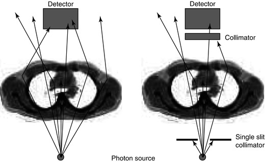
Fig. 1.5
An illustration of the difference between narrow-beam and broad-beam geometry is shown. In the broad-beam case (left) more photons are detected compared to the narrow-beam situation (right) so that the effect of attenuation appears to be lessened. When the source is internally distributed within the body and radiation is being given off in all directions, it is a broad-beam situation
Table 1.2
Attenuation coefficients for commonly used single-photon radionuclides in water*
Radionuclide | Peak (keV) | NIST XCOM | Narrow beam (cm−1) | Broad beam (cm−1) |
|---|---|---|---|---|
Tc-99 m | 140 | 0.151 | 0.149 | 0.121 |
I-131 | 364 | 0.110 | 0.099 | a |
In-111 | 171 | 0.142 | 0.135 | 0.103 |
245 | 0.127 | 0.121 | 0.104 | |
Ga-67 | 93 | 0.169 | 0.171 | 0.153 |
185 | 0.139 | 0.143 | 0.107 | |
300 | 0.118 | 0.123 | 0.099 | |
I-123 | 159 | 0.137 | 0.138 | 0.114 |
Tl-201 | 75–80, 167 | – | 0.159, 0.137 | 0.123 |
1.4 SPECT Instrumentation
1.4.1 Gamma Camera
The workhorse imaging device for SPECT today remains the gamma camera (Fig. 1.6). New solid-state devices have been introduced clinically and will be discussed later. The gamma camera has remained virtually unchanged since its introduction by Anger in the late 1950s. It consists of an inorganic scintillator crystal, sodium iodide doped with small amounts of thallium (NaI(Tl)) to enhance light production, to which is coupled a close-packed array of photomultiplier tubes (PMTs) which converts the light produced by the scintillator into an electrical signal. The electrical signal produced contains information about the location of the photons’ interaction with the crystal plus pulse height spectroscopy (energy deposited in crystal) information.
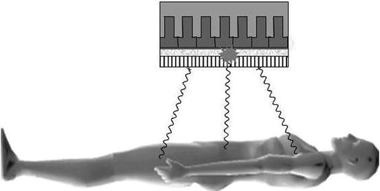
Fig. 1.6
Photons emitted from the subject travelling in a direction orthogonal to the detector pass through the holes of the collimator, while the photons from other angles are attenuated. The photons emit a burst of light which is proportional in intensity to the energy absorbed in the crystal, which is then localised by the photomultiplier tube array
The most common configuration for a SPECT camera today is a dual detector device. This is because this configuration affords the most flexibility in general nuclear medicine imaging, permitting static planar imaging, moving bed whole-body planar scanning, and SPECT with the heads at various relative angles to each other, e.g. 90°, 120°, and 180°. While the gamma camera has retained the same basic design for over 50 years, refinements and improvements in the instrumentation, especially increased digitisation of the signals, have resulted in an extremely stable device suitable for rotation and translation without impacting on image quality.
As the γ-photons are emitted from the subject in all directions, a lead collimator is required between the scintillation crystal and the source to define the parallel lines of response that the photons have taken. The collimator has requirements such as high attenuation (lead is almost always used), thickness, hole shape, length, and width to attenuate the photons that need to be excluded when imaging at a particular orientation to the subject. The resolution of the gamma camera is primarily limited by the geometric resolution of the collimator, which is of the order of 6–9 mm at a distance of 10 cm from the collimator. Overall resolution for the gamma camera is a function of a number of factors including the detector (intrinsic) and collimator (geometric) resolution, the distance from the emitting source to the collimator, the energy of the radionuclide, and the size and density of the object or body being imaged. The sensitivity of the gamma camera is primarily limited by the collimator. The absolute sensitivity in air for a typical gamma camera to a non-attenuating source of 140 keV γ-rays is around 100–200 detected events (counts) per second per MBq (ct.s−1.MBq−1) or around 0.01–0.02 % of all emitted events. The collimator is the component of the imaging chain which places the greatest restriction on gamma camera performance – it has very low sensitivity given the available photon flux, and its geometry imposes limits on the spatial resolution achievable. To compound this, sensitivity and spatial resolution have to be traded against each other to achieve a compromise – high sensitivity giving poor spatial resolution and higher resolution coming with decreased sensitivity.
The energy resolution of the NaI(Tl) scintillator is limited to around 10 % FWHM (Full Width at Half Maximum) in the range 0.1–1.0 MeV. This precludes discriminating against photons that have undergone a scattering interaction within the body from which they originate, with a concomitant loss of energy. The net effect is that around 20–50 % of all events detected by the gamma camera have been scattered within the body, accompanied by a change of direction, which gives rise to mispositioning. This degrades image quality by contributing to an increased background level and therefore decreased contrast. It also confounds attempts to quantify the radionuclide distribution. It is for this reason that scatter correction methods are required for quantitative SPECT reconstructions.
1.4.2 Solid-State Detectors
Recently, dedicated organ-specific SPECT systems with fundamentally different designs to the gamma camera have been introduced. Rather than using a conventional scintillator crystal for photon detection, these new systems use solid-state detectors which are able to convert the absorbed energy from the photon directly into an electrical signal. Due to the cost of these detectors at present, they are being developed for very specific applications such as cardiac imaging. The design for the systems includes a large number of small detectors (~10–30) which are located in a fixed position. These systems are SPECT-only devices not capable of forming planar images. Collimation is usually done using simple pinhole designs, and the reconstruction is tailored to the unique geometry of the system. Among the attractive features of these systems are high sensitivity due to the large number of detectors focused on a small field of view and improved energy resolution compared with NaI(Tl). The improved energy resolution presents the possibility of simultaneous imaging of different radionuclides with similar photon energies (e.g. 99mTc (140 keV) and 123I (159 keV)). The systems can be used for more rapid image acquisition due to the improved sensitivity with reductions of four to tenfold reported. Alternately, the improvement in sensitivity can be used to reduce the amount of radioactivity injected and hence reduce the radiation dose received by the subject.
1.5 SPECT Acquisition and Reconstruction
1.5.1 Projections and the Radon Transform
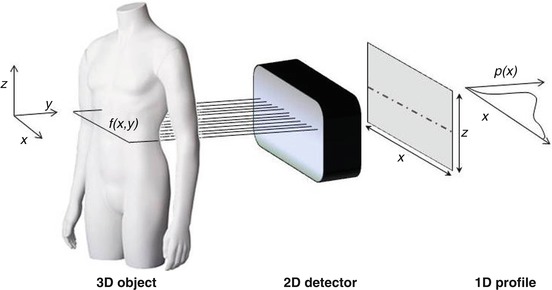
Tomographic imaging is the art of reconstructing the internal distribution of the signal of interest from external measurements. The same principles for image formation are employed in CT, SPECT, and PET as well as in other imaging modalities such as confocal microscopy. High-energy photons are used because of their ability to pass through the body with subsequent detection by an external device.
The tomographic imaging process for SPECT is shown in Fig. 1.7. Photons are emitted from the subject at all angles, but the collimator on the gamma camera selects only those travelling in the required direction at a particular angle of the detector relative to the subject. As seen in Fig. 1.7, each row on the detector is composed of a series of parallel projections. The projections are proportional to the sum of the intensities of the radionuclide concentration along the particular line of sight through the subject. This can be written (ignoring photon attenuation at present) as
where p(x r,ϕ) is the one-dimensional projection of the two-dimensional function f(x,y) in a rotating frame of reference (indicated by the subscript ‘r’) at the angle ϕ. This is known as a radon (or ‘X-ray’) transform – p(x r,ϕ) is the radon transform of f(x,y) at angle ϕ. The reconstruction of f(x,y) from the projections is known as an ‘inverse problem’. Note that the dimensionality of the original function f(x,y), 2D, is reduced by one in the projection to a 1D profile. However, if multiple 1D projections at different angles over 180° or 360° are acquired, rotating about the z-axis, the 2D function f(x,y) can be recovered using the solution provide by the Central Slice Theorem. This relates the projections and the original distribution f(x,y) as the Fourier transform of a projection p(x r,ϕ) of a distribution f(x,y) is equal to a section through the Fourier transform of the distribution f(x,y) at the same angle (ϕ) as the projection. For a more detailed discussion of this important concept, the reader is referred to one of the following texts on the topic [16–18].
(1.3)
Fig. 1.7
The acquisition geometry is defined for SPECT acquisitions. The (x,y) co-ordinate system rotates about the z-axis to acquire projection (p(x)) at different angles. A section through the three-dimensional radionuclide distribution in the subject (f(x,y)) is recorded by the detector as a 2D radon transform. Each 1D profile in the planar image is then treated independently in the reconstruction process
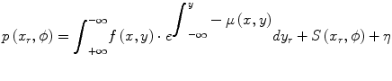
The SPECT reconstruction problem is complicated by the fact that there are extra terms which were ignored, for clarity, in Eq. 1.3. A more complete description of the projection p(x r,ϕ) is shown below where there is an additional attenuation term in the integrand and there are additive terms to account for scatter (S) and Poisson (random) noise (η).
(1.4)
1.5.2 Image Reconstruction: Filtered Back-Projection (FBP)
The classical method for image reconstruction in emission tomography is the filtered back-projection algorithm (Fig. 1.8


Related posts:

Stay updated, free articles. Join our Telegram channel
Full access? Get Clinical Tree
