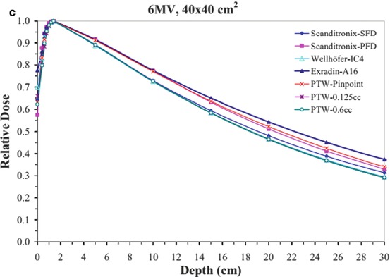
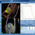
Fig. 4.1
Depth dose data for a 6 MV beam for (a) 1 × 1 cm2, (b) 10 × 10 cm2, and (c) 40 × 40 cm2 fields using different detectors (From Klein et al. [1]; used with permission)
Table 4.1
Output factors; the agreement between different dosimeters is good down to a 2 × 2 cm2 field
Field (cm) | Diamond IC15 | Wellhofer A14SL | Exradin pinpoint | PTW A16 | Exradin |
|---|---|---|---|---|---|
1 | 0.639 | 0.512 | 0.541 | 0.561 | 0.643 |
2 | 0.788 | 0.786 | 0.769 | 0.777 | 0.786 |
3 | 0.831 | 0.832 | 0.827 | 0.829 | 0.829 |
4 | 0.866 | 0.866 | 0.866 | 0.867 | 0.864 |
5 | 0.898 | 0.898 | 0.896 | 0.898 | 0.895 |
10 | 1 | 1 | 1 | 1.014 | 1 |
15 | 1.062 | 1.058 | 1.062 | 1.089 | 1.07 |
20 | 1.098 | 1.096 | 1.098 | 1.146 | 1.117 |
Accurate detector-water scanner configuration with respect to the beam central axis and center of detector is critical. Li et al. [9] have demonstrated large errors can be caused due to small measurement displacement from beam central axis. Even with accurate detector-water scanner configuration, there can still be greater than 10 % discrepancies among measurement of small fields [2]. See Figs. 4.2 and 4.3 explaining the effect of scanning arm tilt and gantry angle tilt on the measured beam data. It is imperative that a thorough check is performed on the robustness of the data scanning equipment and setup prior to commencing the final beam data collection process.
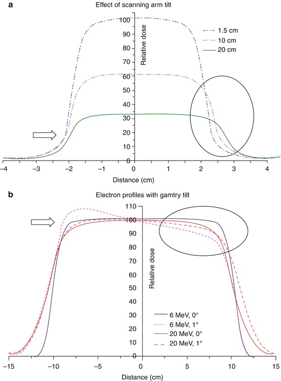
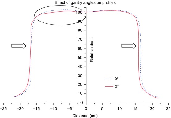
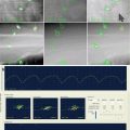
Fig. 4.2
(a) Beam profiles of a 6 MV beam at different depths with scanning arm tilt for a 4 × 4 cm2 field, (b) Electron beam profiles at depth of 80 % depth dose for 20 × 20 cm2 cone with gantry tilt. Arrows and circle shown to represent the impact of arm and gantry tilt (From Klein et al. [1]; used with permission)
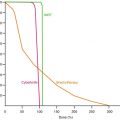
Fig. 4.3
Effect of gantry angle tilt on the profiles of a 6 MV beam for 30 × 30 cm2 field at 10 cm depth (From Klein et al. [1]; used with permission)
Examples of data scanning: SBRT systems use either circular collimator and/or mMLC for beam shaping. Cyberknife uses both circular cones and an IRIS collimator (variable aperture MLC) whereas Novalis uses both circular cones and mMLC. Cyberknife systems are commonly commissioned with solid state diode detectors (PTW 60012, 60018- PTW Freiburg) for all relative measurements as recommended by the vendor. This provides excellent opportunity for data comparison among large numbers of users. This can assist an individual site to ensure their data is not outside of the expected tolerance and prevent potentially large dosimetric errors. The mMLC type systems have been commissioned with a range of detectors including mini-ion chamber, diode detectors and film [10].
Non scanned beam data, such as the total scatter (output) factors must be measured under full scatter conditions in the water phantom. Typically they are measured at the SSD or SAD setting as used for absolute dose calibration. In air output factors for SBRT field sizes must be measured at an extended distance so as to ensure adequate coverage of the field size in relation to the detector size. They should be measured with a build-up cap or mini phantom sufficiently large enough to provide electronic equilibrium and not be affected by electron contamination in the beam which can produce erroneous results. The minimum field size is determined by the requirement that there is sufficient “flash” of at least 1 cm around the mini-phantom [3].
4.2.3 TPS Commissioning
TPS commissioning must be performed [4] to ensure the planned dose matches the delivered dose prior to start of a clinical SBRT program. This must include not only spot check validation with simple beam geometry in a uniform water phantom but also complex field setups that include heterogeneity to simulate patient setup. Anthropomorphic phantoms provide a useful way to determine the overall accuracy of the acquired data and TPS dose calculation algorithm accuracy. The Radiological Physics Center (RPC) provides such phantoms for various body sections, for sites participating in Radiation Therapy Oncology Group (RTOG). Alternatively, they may be obtained from Radiation Doimetry Services (RDS) at MD Anderson Cancer Center, Houston, TX. Additionally, end-to-end analysis with phantoms imbedded with known objects with film provide overall system imaging, mechanical and dosimetry accuracy.
4.3 Quality Assurance
For any system that is used for SBRT or SRS, which delivers a very high dose to a region in a single or a very small number of fractions, a systematic evaluation of the treatment accuracy is required. This would include CT/MR imaging, fusion uncertainties, planning calculation, target localization and then dose delivery. AAPM Task Group 101 report on “Stereotactic Body Radiation Therapy” Section VII.B states that “Specific tests should be developed to look at all aspects of the system both individually and in an integrated fashion” [2].
In this section, we are assuming that routine quality assurance has been conducted for the accuracy of CT/MR imaging, fusion and the treatment planning system, and will concentrate on the quality assurance procedures needed for target localization and dosimetry.
Ensuring target localization accuracy is a top priority for SBRT/SRS treatments. Because of the high dose delivered per fraction, any slight deviation in targeting accuracy could result in potentially damaging dose to the normal tissue, and it may be impossible to correct for any such errors in radiation delivery by modifying subsequent fractions. The standard for determining this targeting accuracy is the “Winston-Lutz” test or similar procedures for frameless SRS/SBRT procedures [11].
Since most of the currently available SBRT systems utilize either stereoscopic localization x-rays or CBCT for target localization and patient set up, in addition to the basic check on treatment beam and imaging isocenter, microMLC positioning, quality assurance on the imaging system and couch shift positioning accuracy is also needed. For any IGRT procedures that are used to ensure target localization accuracy, quality assurance of the imaging system is essential, following the test and frequency as shown in Table 4.2.
Table 4.2
Summary of relevant imaging tolerances for SRS/SBRT
Daily | |
Procedure | Tolerance |
Planar kV and MV (EPID) imaging | SRS/SBRT |
Collision interlocks | Functional |
Positioning/repositioning | ≦1 mm |
Imaging and treatment coordinate coincidence (single gantry angle) | ≦1 mm |
Cone-beam CT (kV and MV) | |
Collision interlocks | Functional |
Imaging and treatment coordinate coincidence | ≦1 mm |
Positioning/repositioning | ≦1 mm |
Monthly | |
Contrast | Baseline |
Imaging and treatment coordinate coincidence (four cardinal angles) | ≦1 mm |
Scaling | ≦2 mm |
Spatial resolution | Baseline |
Contrast | Baseline |
Uniformity and noise | Baseline |
Planar kV imaging | |
Imaging and treatment coordinate coincidence (four cardinal angles) | ≦1 mm |
Scaling | ≦1 mm |
Spatial resolution | Baseline |
Contrast | Baseline |
Uniformity and noise | Baseline |
Cone-beam CT (kV and MV) | |
Geometric distortion | ≦1 mm |
Spatial resolution | Baseline |
HU constancy | Baseline |
Uniformity and noise | Baseline |
Annual | |
Planar MV imaging (EPID) | |
Full range of travel SDD | ≦5 mm |
Imaging dose | Baseline |
Planar kV imaging | |
Beam quality/energy | Baseline |
Imaging dose | Baseline |
Cone-beam CT (kV and MV) | |
Imaging dose | Baseline |
4.3.1 Imaging System Quality Assurance
Since the primary goal of an IGRT system is to localize target and organs at risk in the treatment room and derive correction strategies to minimize geometric uncertainties, any significant deviation from baseline could impact the accuracy of the IGRT system. Therefore, it is essential that the imaging system performance is kept at an optimal level with the highest accuracy possible. Both the kV-CBCT and MV-CBCT systems necessitate calibration procedures to properly register the treatment beam isocenter and correct for accelerator and imaging component sags and flexes, to certify the geometric accuracy of the imaged guided procedures.
In addition, image quality, scale and distance accuracy, contrast resolution, spatial and contrast resolution, noise, image registration accuracy and the accuracy of remote controlled couch are also important aspects of quality assurance for these systems. These aspects and patient safety all need to be part of a regularly scheduled QA program designed and managed by medical physicists.
The importance of quality assurance for on-line imaging systems has been recognized by the community and by AAPM (Task Group 142: QA of Medical Accelerators – this report has a section on imager QA). Tables 4.2 and 4.3 specify the frequency and tolerance of certain tasks that is recommended for both planar and cone beam images. The tasks include (1) safety and functionality; (2) geometrical accuracy: Imager isocenter accuracy, 2D2D match and couch shift accuracy, Image magnification accuracy, Imager isocenter accuracy with gantry rotation; (3) image quality: Contrast and spatial resolution, Hounsefield Units linearity and uniformity, In-slice spatial linearity and slice thickness [1].
Table 4.3
Summary of relevant tolerances for SRS/SBRT
Daily | |
Procedure | Tolerance |
Laser localization | 1 mm |
Distance indicator (ODI) @ iso | 2 mm |
Collimator size indicator | 1 mm |
Monthly | |
Typical dose rate output constancy | 2 % (@ stereo dose rate) |
Treatment couch position indicators | 1 mm/0.5° |
Localizing lasers | <±1 mm |
Annual | |
Typical dose rate output constancy | 2 % |
Treatment couch position indicators | 1 mm/0.5° |
Localizing lasers | <±1 mm |
SRS arc rotation mode (range: 0.5–10 MU/deg) | Monitor units set vs. delivered: 1.0 MU or 2 % |
Gantry arc set vs delivered: 1° or 2 % | |
X-ray monitor unit linearity (output constancy) | ±5 % (2–4 MU), ±2 % ≥5 MU
Related posts: Stereotactic Body Radiotherapy for Oligometastasis
Stereotactic Body Radiotherapy for Bone and Soft Tissue Sarcoma Stereotactic Body Radiotherapy for Oligometastasis
Stereotactic Body Radiotherapy for Bone and Soft Tissue Sarcoma
 Stereotactic Body Radiotherapy (SBRT) for Pancreatic Cancer Stereotactic Body Radiotherapy (SBRT) for Pancreatic Cancer
 Stereotactic Body Radiation Therapy to Liver Stereotactic Body Radiation Therapy to Liver
 Stereotactic Body Radiotherapy in Head and Neck Cancer Stereotactic Body Radiotherapy in Head and Neck Cancer
 Stereotactic Body Radiotherapy: A Practical Guide for the Delivery of Accelerated Partial Breast Irradiation Stereotactic Body Radiotherapy: A Practical Guide for the Delivery of Accelerated Partial Breast Irradiation
Stay updated, free articles. Join our Telegram channel
Full access? Get Clinical Tree
 Get Clinical Tree app for offline access

|