Characteristic
Conventional RT
SRS/ SBRT
Prescription dose per fraction
≤3 Gy
≥5 Gy
Number of fractions
≥10
≤5
Dose distribution
Homogeneous (max PTV dose ≈105–110 %)
Heterogeneous (max PTV dose ≈110–200 %)a
Dose gradient outside PTV
Shallow slope
Steep slope
Prescription isodose line
≈90–95 %
≈50–95 %a
Target definition
Tumor might not have a sharp boundary
Well-delineated target
PTV margin
≈cm
≈mm
Patient setup and immobilization device s vary depending on body site, treatment platform, and the capability of the delivery system to detect and correct for changes in patient position during treatment.
The stereotactic coordinate system is provided either by an invasive fixation device (head frame ) or by the imaging system (frameless radiosurgery ).
SRS : Stereotactic head frame attached to the patient’s skull using pins (Khan 2003). Frameless system could include thermoplastic mask with reflective markers and vacuum-assisted mouthpieces.
SBRT : body frame s, body cast , and vacuum bags (Table 3.2).
Table 3.2
Reported accuracy of commercially available SBRT immobilization device s (Taylor et al. 2011)
Site
System
Reported accuracy (mm)
Lung
Elekta body frame
1.8–5
MI body fix
2.5–3
Leinbinger body frame
2–4.4
Liver
Elekta body frame
≤4.4
MI body fix
≤3.2
Leinbinger body frame
1.8–4.4
Spine
MI body fix
≈1
Body cast
≈3
Fiducial marker tracking
2
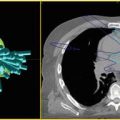
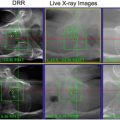
Imaging techniques for SRS /SBRT treatment verification (Murphy et al. 2007; German et al. 2001; Broderick et al. 2007; Li et al. 2008; Jin et al. 2008): 2D MV electronic portal imaging (EPID) .
Orthogonal kV radiographs.
MV cone beam CT.
kV cone beam CT .
MV helical CT.
In-room diagnostic CT.
4DCBCT.
Infrared imaging .
Radiofrequency tracking .
Management of respiratory motion for SBRT motion-encompassing techniques (4DCT—ITV delineation).
Abdominal compression—this method reduces the target excursion with breathing.
Breath-hold—radiation is delivered when the patient is holding the breath.
Gating —radiation is delivered only at a particular phase of respiration.
Dynamic target tracking—beams are re-targeted in real time to the continuously changing target position—advantages: no need for ITV expansion; no treatment interruptions; accounts for changes in target motion and respiratory pattern during treatment.
SRS/SBRT Treatment Parameters
Target volumes: The concept of GTV , CTV , PTV , and ITV described in ICRU 50 and 62 for SRS also applies to SBRT planning (Medin et al. 2010; ICRU 1993). PTV margins depend on body site, treatment device, localization technique, and imaging frequency. Typical margins range from 2 to 5 mm for SBRT.
Dose conformity: the high-dose volume conforms tightly around the target.
Dose heterogeneity : hot spots located within the target are often considered not only acceptable, but also desirable. The prescription dose is typically 50–90 % of the maximum dose depending on the treatment delivery and treatment planning systems.
Dose gradient : the dose fall-off away from the target is steep. The volume of normal tissue receiving high doses of radiation is kept at a minimum. This is in comparison with other treatment techniques like 3D conformal.
Beam energy: 6 MV photons offer the best compromise between beam penetration and penumbra characteristics. Many techniques use unflattened beams .
Beam shaping: Radiation is collimated to a small field using heavy metal cones (circular field 4–60 mm diameters), multileaf collimator (MLCs), or microMLCs (2.5 mm leaves width). MLCs and micro MLCs are used to deliver treatments developed with conformal beams, intensity modulated fields, dynamic conformal arcs , or a combination of these (ICRU 1999).
Treatments are delivered via coplanar and non-coplanar beam arrangements.
Circular fields provide a sharper penumbra than microMLCs.
Beam geometry: multiple non-overlapping beams concentrically pointing to the target; 5–12 coplanar or non-coplanar beams; 1 or 2 coplanar or non-coplanar arcs; a continuously rotating fan beam; hundreds of non-coplanar pencil beams pointing to different parts of the target (non-isocentric beam arrangement) or to the same point (isocentric beam arrangement).
Plan Optimization
Forward planning : the user manually adjusts beam arrangement, field shapes, and weights until the desirable dose distribution is achieved.
Inverse planning : the user specifies plan objectives for target and normal structures and a dose optimization algorithm calculates field shapes and weights based on the minimization of a mathematical cost function.
Plan Classification
3-Dimensional conformal radiation therapy (3D-CRT ): typically forward planned. It might be advantageous for moving targets, as the target is always in the open radiation field.
Intensity-modulated radiation therapy (IMRT ): typically inverse planned (although the field-in-field technique is forward planned).
Arc therapy (RapidArc , VMAT ).
Dose Calculation Algorithms
Pencil beam algorithms using radiological path length corrections to account for tissue heterogeneities. Not accurate in conditions of electronic disequilibrium . In these cases, heterogeneity corrections explicitly accounting for the transport of secondary electrons must be employed. While the most accurate technique for dose calculation is Monte Carlo , convolution-superposition methods are sufficiently accurate in most clinical situations.
Calculation grid : should be less than 2 × 2 × 2 mm3.
Treatment Platforms and Cross-Platform Comparisons
SRS /SBRT treatments can be performed using a variety of devices producing X rays, gamma rays or particle radiation (Tables 3.3 and 3.4) (Combs et al. 2012; Dieterich and Gibbs 2011; Soisson et al. 2006):
Table 3.3
Characteristics of various platforms for SRS /SBRT
Technology
Delivery system
Radiation
Dose rate
Beam shaping
CyberKnife
Compact linac mounted on a robotic arm
6 MV unflattened photon beam
Up to 1000 MU/min
12 Interchangeable tungsten cones; variable aperture collimator; MLC (not yet clinically available)
Tomotherapy
Helical, CT-like gantry equipped with a linac waveguide
6 MV unflattened photon beam
~850 cGy/min at isocenter
Binary MLC (64 leaves, 0.625 cm wide)
Gamma knife
192 (Perfexion) or 201 (models B-4C) 60Co sources
1.17 and 1.33 MeV gamma rays
Initial source activity ~6000 Ci, dose-rate at focal point >3 Gy/min
Tungsten barrel subdivided into 8 sectors (Perfexion) ; 4 interchangeable helmets (models B-4C)
Linac-based systems
Gantry-based linac rotating about the isocenter
Multiphoton energies (6, 10, 15, 18 MV-flattened and unflattened) and electron energiesRelated posts:

Stay updated, free articles. Join our Telegram channel

Full access? Get Clinical Tree

 Get Clinical Tree app for offline access