Fig. 7.1
a An eventual new lesion (transparent) would not modify the surgical strategy if the chosen operation is a right hepatectomy (red line representing the dissection plane); b an eventual new lesion (transparent) would modify the surgical strategy if the chosen operation is multiple resection (red line representing the dissection planes and the dashed yellow the additional one)
IOUS allows an accurate three-dimensional reconstruction of the relationship between the tumor, the portal branches, and hepatic veins: this is a prerequisite for defining a surgical strategy based on a new principle. The insights gained from IOUS, rather than allowing a safer removal of large amounts of liver parenchyma as conventionally recommended [4, 5], can be thought as aiming at maximizing the conservation of the liver vascular skeleton, while still involving oncological radicality. This approach per se implies leaving enough liver with proper inflow and outflow. For these targets, exposure carried out for staging the disease intraoperatively is often not sufficient. Planning a surgical strategy, one needs to assemble all available inspective, tactile, and ultrasound information and the liver exposure and mobilization need to be accordingly carried out. To better determine the tumor-vessel relationship in a three-dimensional setting, the position of the surgeon’s left hand as well as the tumor should be depicted in the IOUS images (Fig. 7.2a, b) similarly as it will be described for resection guidance: the palpation feedback and IOUS image need to be assembled in the surgeon’s mind for determining the best approach for tumor removal. Also, knowledge of the liver inflow and outflow by IOUS is crucial for determining the feasibility of new surgical procedures that are otherwise unfeasible: for this purpose an adequate surgical field, with proper liver mobilization, can allow maneuvers of vessel compression or taping indispensable—all information needed to decide whether or not a certain approach is feasible. A first prerequisite is an adequate liver exposure and mobilization, as further detailed in Chap. 8 focusing on resection guidance.
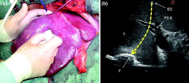
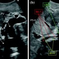
Fig. 7.2
a The surgeon’s fingertip and the probe act simultaneously to draw the ideal dissection plane to be followed; b the corresponding IOUS image in which the yellow dashed line indicates the ideal plane connecting the fingertip (F) and the shadow generated by the electrocautery (EC) interposed between the liver surface and the probe; portal branch to the right anterior section (P5–8); tumor (T)
7.1 Tumor–Vessel Relationship
Depending on the tumor–vessels relationship, specific and original operations can be performed [6–8]. IOUS easily allows the surgeon to recognize if an HCC is separated by some normal parenchyma from the vessel, or if it is in contact with the vessel without invading its wall, or conversely, whether the HCC has invaded the vessel wall, whether it determines the proximal bile duct dilation, or is associated with a tumor thrombus [9]. Also, determination of the relationship between a CLM and intrahepatic vascular structure is precisely definable by IOUS: in this respect, if the vessel wall is found to be intact, also the circumferential extent of the contact is relevant for deciding on a resection sparing the vessel in contact with the CLM [3]. Based on these features, the decision whether the vessel should be resected or not is taken and a precise surgical strategy can be defined.
7.1.1 Tumor in Contact with a Glissonian Pedicle
The glissonian pedicle in contact with a capsulated HCC is spared in case of integrity of the vessel wall in IOUS without any sign of bile duct dilation (Fig. 7.3a–d) [9]. Similarly, the pedicle can be spared when it is in contact with a CLM once IOUS has confirmed the integrity of the vessel wall and bile duct dilation is ruled out, and the extent of contact is up to two-third of the pedicle circumference (Fig. 7.4a–d) [3]. In case of bile duct dilation (Fig. 7.5a, b), invasion of the vessel wall (Fig. 7.6a, c), and, for CLM, contact wider than two-thirds of pedicle circumference (Fig. 7.6b, c), the glissonian triad has to be divided. Of course, the pedicle has to be also sacrificed in case of a tumor thrombus in the portal branch (Fig. 7.7a, b), in the bile duct (Fig. 7.8a, b), or in both (Fig. 7.9). In these cases, extension of the hepatectomy is always considered.
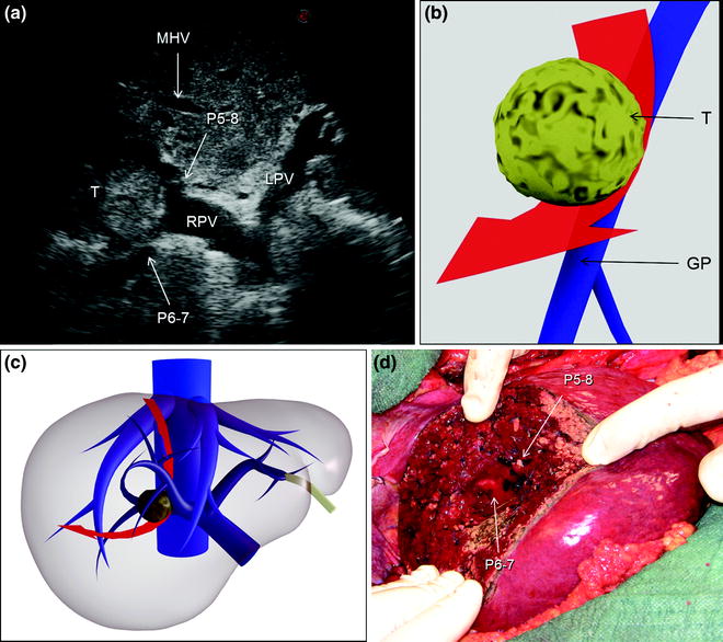
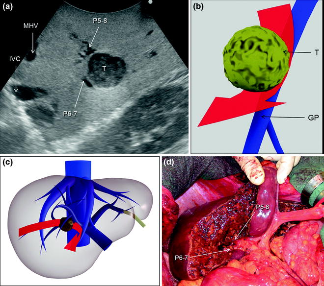
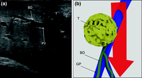
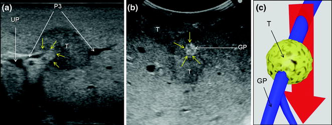
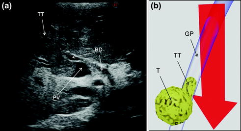
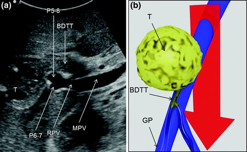
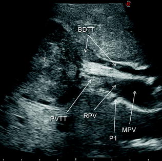
Fig. 7.3
a An HCC (T) located at the bifurcation between the portal branch to the right anterior section (P5–8) and that to the right posterior (P6–7); b schematically this lesion could be classified as shown and as consequence a detachment of T from the glissonian pedicle (GP) would be feasible, and the drawn dissection line (red arrow) is planned; c accordingly, the operation is planned; d finally, the roots of P5-8 and P6-7 are exposed on the cut surface; left portal vein (LPV); middle hepatic vein (MHV); right portal vein (RPV)
Fig. 7.4
a A colorectal liver metastasis (T) located at the bifurcation between the portal branch to the right anterior section (P5–8) and that to the right posterior (P6–7); b schematically this lesion can be classified as shown and accordingly a detachment of T from the glissonian pedicle (GP) is feasible; the dissection line is planned (red arrow); c accordingly, the operation is planned; d finally, the roots of P5-8 and P6-7 are exposed on the cut surface: inferior vena cava (IVC); middle hepatic vein (MHV)
Fig. 7.5
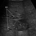
a This picture shows a colorectal liver metastases (T) in contact with a glissonian pedicle (GP) and determining bile duct dilation (BD); b schematically this lesion can be classified as shown; accordingly, a detachment of T from GP is not feasible; the dissection line (red arrow) is planned; portal vein (PV)
Fig. 7.6
a A colorectal liver metastasis (T) invading (yellow arrows) the glissonian pedicle of segment 3 (P3); b a colorectal liver metastasis (T) in extensive contact (yellow arrows) with a glissonian pedicle (GP); c schematically these lesions can be classified as shown and, accordingly, a detachment of T from the GP is not feasible; the dissection line (red arrow) is planned; umbilical portion (UP)
Fig. 7.7
a An HCC (T) invading the portal vein (PV) with a tumor thrombus (TT); b schematically this lesion can be classified as shown and, accordingly, a detachment of T from the glissonian pedicle (GP) is not feasible; the dissection line (red arrow) is planned; bile duct (BD)
Fig. 7.8
a An HCC (T) invading the bile duct with a tumor thrombus (BDTT); b schematically this lesion can be classified as shown and, accordingly, a detachment of T from the glissonian pedicle (GP) is not feasible; the dissection line (red arrow) is planned; main portal vein (MPV); portal branch to the right anterior section (P5–8); portal branch to the right posterior section (P6–7); right portal vein (RPV)
Fig. 7.9
An HCC (T) invading the bile duct (BDTT) and also the portal vein (PVTT) with a tumor thrombus: main portal vein (MPV); portal branch to segment 1 (P1); right portal vein (RPV)
7.1.1.1 Conservative Resection of Centrally Located Tumors
The principal output of this approach is to make feasible small-size resections even in the presence of a tumor in contact with first- or second-order portal branches, which can be represented schematically by a new resection planning as shown in Fig. 7.10. That becomes feasible by performing more complex dissection under strict IOUS guidance (Fig. 7.11a–e), and even standardizing procedures based on the pattern of lesion distribution and IOUS tumor–vessel relationships: this is the case for the so-called lower inferior hepatectomy (Fig. 7.12a–p) and liver tunnel (Fig. 7.13a–f).
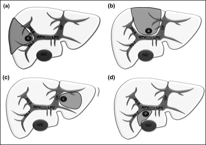
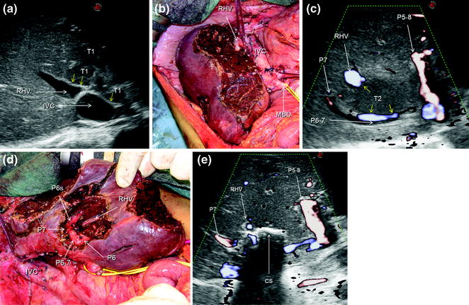
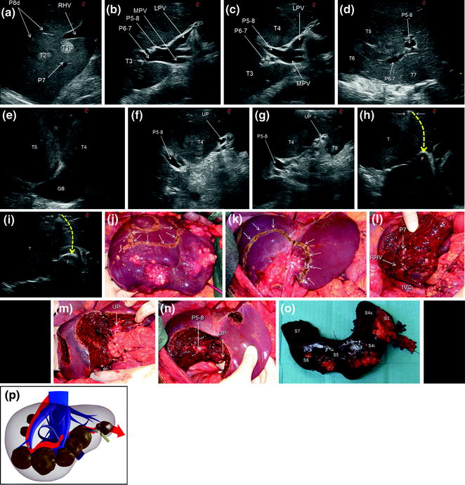
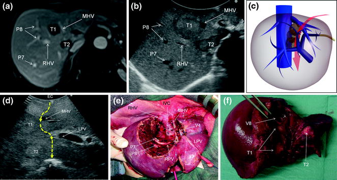
Fig. 7.10
Resection areas (gray) adopted for lesions centrally located due to contact with the first- or second-order glissonian pedicles in (a) on the right (R), in (b) anteriorly (A), in (c) on the left (L), and in (d) posteriorly (P); inferior vena cava (IVC); left portal vein (LPV); portal branch to the right anterior section (P5–8); portal branch to the right posterior section (P6–7); right portal vein (RPV); umbilical portion (UP)
Fig. 7.11
a IOUS image of a huge confluent colorectal liver metastasis (T1) occupying entirely the left liver, segment 1, and part of the right anterior section, being in contact (yellow arrows) with the right hepatic vein (RHV) at its confluence into the inferior vena cava (IVC); b the cut surface after left hepatectomy extended to segment 1 and the right anterior section; c IOUS precisely discloses the presence of a lesion (T2) in contact (yellow arrows) with the RHV, and the portal branch to the right posterior section (P6–7) to which in part is lying posteriorly; d finally, the cut surface is showing the RHV, and branches to segment 6 (P6), 6 superior (P6s), and 7 (P7); e by IOUS, examining from the opposite side of the cut surface (CS), it is possible to verify the emptiness of the space previously occupied by the lesion and simultaneously the patency of the detached vessels; portal branch to the right anterior section (P5–8)
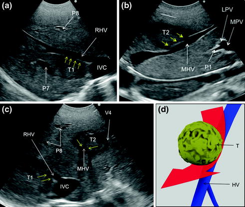
Fig. 7.12
a IOUS image of two colorectal liver metastases (T1, T2) in segment 7; b IOUS image of a colorectal liver metastasis (T3) below the root of the branch for the right posterior section (P6–7); c IOUS image of a colorectal liver metastasis (T3) below the root of P6-7 and another (T4) just in front of the left portal vein (LPV) and the branch for the right anterior section (P5–8); d IOUS image of two colorectal liver metastases (T5, T6) adjacent to P6-7 and P5-8, and another (T7) in the caudate process of segment 1; e IOUS image of two colorectal liver metastases (T4, T5) above the gallbladder (GB); f IOUS image of a colorectal liver metastasis (T4) between P5-8 and the umbilical portion (UP); g IOUS image of the colorectal liver metastasis described in (f) (T4), and of another located in segment 3 (T8); h, i two phases of the procedure performed for disclosing by IOUS the margins of the wide resection area by using the probe, the electrocautery (white arrows), and the finger (F) for planning the dissection plane (yellow dashed arrows); j, k the margins (arrows) once drawn on the liver surface; l, m, n the cut surface at the end of the resection; o specimen removed; p the schema of the procedure carried out and denominated lower inferior hepatectomy with the dissection plane detailed in red; inferior vena cava (IVC); main portal vein (MPV); right hepatic vein (RHV); portal branch to segment 7 (P7); portal branches to segment 8 dorsal (P8); segment 3 (S3); segment 4 inferior (S4i); segment 4 superior (S4s); segment 5 (S5); segment 6 (S6); segment 7 (S7)
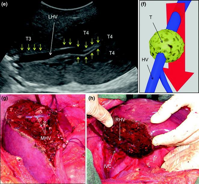
Fig. 7.13
a MRI image of two colorectal liver metastases in segment 8 (T1) and 1 (T2); b IOUS image of T1 and T2, which compose a sort of cascade of lesions from segment 8 to 1; c main dissection plane (red arrow) followed for removing the two lesions: indeed T1 and T2 occupy an area disclosed in the schema by the transparent lesions, where any large and/or multiple lesions in our opinion justify a so-called ‘‘liver tunnel’’ parenchyma-sparing procedure; d IOUS image of the dissection (dashed yellow arrows) followed for removing these two lesions; e the cut surface resulting at the end of the resection: so-called ‘‘liver tunnel’’; f specimen with tumor exposure of the metastases (T1, T2), which correspond to the portions of the lesions in contact with the middle hepatic vein (MHV) (T1), and the posterior wall of the portal bifurcation (T2); electrocautery (EC); finger (F); inferior vena cava (IVC); left portal vein (LPV); right hepatic vein (RHV); right portal vein (RPV); portal branch to segment 7 (P7); portal branch to segment 8 (P8); hepatic vein draining segment 4 (V4); hepatic vein draining segment 8 (V8)
7.1.2 Tumor in Contact with an Hepatic Vein
The hepatic vein is usually spared when in contact with an encapsulated HCC having the integrity of the vessel wall in IOUS (Fig. 7.14a–c). Initially for the CLM, its contact was considered an indication for hepatic vein resection. Nowadays, the vein is spared when it is in contact with a CLM, but the integrity of the vessel wall is confirmed at IOUS, and the contact extension is less than two-thirds of the vein’s circumference (Fig. 7.15a, b): this allows sparing procedures, which lead to otherwise unfeasible operations (Fig. 7.16a–h). When the nondetachable contact extension achieves almost 2/3, there are no communicating veins (CV), but sparing is recommended due to the association of other simultaneous resections, if part of the vessel wall is still free of tumor, patching is carried out and color-flow IOUS (CFIOUS) is used to check the patency of the vein (Fig. 7.17a–c). In presence of tumor thrombus (Fig. 7.18a–c), invasion of the vessel wall (Fig. 7.19a), and, for CLM, contact wider than two-thirds of the vein’s circumference (Fig. 7.19b), the hepatic vein has to be divided (Fig. 7.19c). In these cases, extension of the hepatectomy is not compulsorily considered even if the hepatic vein is invaded at its caval confluence (last 4 cm). An extension of the resection to the entire liver parenchyma theoretically drained by the hepatic vein to be resected, is considered only if one of the following ultrasonographic signs is missing:
Get Clinical Tree app for offline access
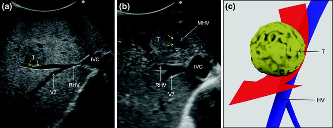
Fig. 7.14
a An HCC (T) in contact (yellow arrows) with the right hepatic vein (RHV); b an HCC (T) in contact (yellow arrows) with the middle hepatic vein (MHV); c schematically these lesions can be classified as shown and in consequence a detachment of the tumor from the hepatic veins (HV) may be feasible, and the drawn dissection line (red arrow) is planned; inferior vena cava (IVC); hepatic vein draining segment 7 (V7)
Fig. 7.15
a Colorectal liver metastasis (T) in contact with the middle hepatic vein (MHV) for an extension lower or equal than 2/3; b schematically this lesion can be classified as shown and in consequence a detachment of the tumor from the hepatic veins (HV) may be feasible, and the drawn dissection line (red arrow) is planned; inferior vena cava (IVC); right hepatic vein (RHV)
Fig. 7.16
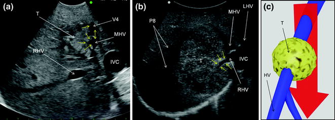
a IOUS image of a colorectal liver metastasis in segment 7 (T1) in contact (yellow arrows) with the right hepatic vein (RHV); b IOUS image of a colorectal liver metastasis in segments 4 superior and 8 (T2) in contact (yellow arrows) with the middle hepatic vein (MHV); c transverse scan at IOUS of T1, T2 in contact (yellow arrows) respectively with the RHV and MHV; d dissection (red arrow) followed for removing these two lesions; e IOUS image of a colorectal liver metastasis (T3) in contact (yellow arrows) with the left hepatic vein (LHV) at the caval confluence and another (T4) which infiltrates (yellow arrows) the LHV just peripherally in respect to T3; f dissection (red arrow) followed for removing these two lesions which is motivated by the type of relationship between T4 and LHV; g, h cut surface for removing those lesions depicted in the previous pictures: in particular, MHV was detached from T2 (g) and RHV from T1 (h); hepatic vein (HV); inferior vena cava (IVC); left portal vein (LPV); main portal vein (MPV); portal branch to segment 1 (P1); portal branch to segment 7 (P7); portal branch to segment 8 (P8); hepatic vein draining segment 4 (V4)
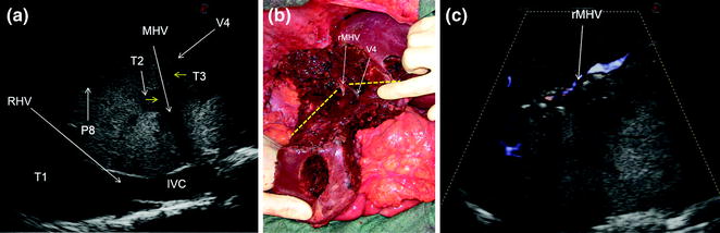
Fig. 7.17
a IOUS image of 3 out of 15 colorectal liver metastases (T1, T2, T3): two of them (T2, T3) have a contact (yellow arrows) with the mid-portion of the middle hepatic vein (MHV) and the branch draining segment 4 (V4); b the association of the two lesions close to each others and surrounding MHV and V4 at their junction made unfeasible their detachment without resection of a portion of vessel wall; the absence of communicating veins lead to vein reconstruction performed with a patch of bovine pericardium (rMHV) to allow proper drainage of a relevant part of remnant liver (the portion of liver located inferiorly to the two yellow dashes lines) considering the sacrificed parenchyma for having removed the other lesions distributed on both lobes; c CFIOUS image confirming the patency of the reconstructed vein: inferior vena cava (IVC); portal branch to segment 8 (P8)
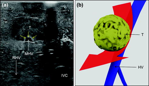
Fig. 7.18
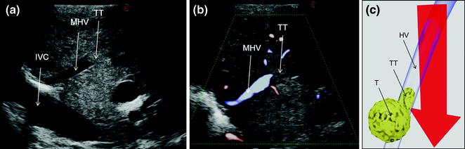
a IOUS of an HCC having invaded with a tumor thrombus (TT) the middle hepatic vein (MHV); b CFIOUS image of that previously shown in (a); c schematically this lesion can be classified as shown and in consequence the dissection line (red arrow) has to consider hepatic vein (HV) resection; inferior vena cava (IVC); tumor (T)
Fig. 7.19
a IOUS image of a colorectal liver metastasis (T) invading (yellow arrows) the middle hepatic vein (MHV), and the vein draining segment 4 (V4
 Liver Transplantation from Living Donors
 Technical Tricks to Start Exploring the Liver with Ultrasound
 Diagnosis and Staging: Contrast-Enhanced Intraoperative Ultrasound (CEIOUS) Using Intravascular Contrast Agents
 Intraoperative Cholangio Ultrasound in the Study of the Biliary Tree
 Technological Requirements for Ultrasound-Guided Liver Surgery
 Exploring the Liver by Ultrasound Along its Anatomy


Related posts:
Liver Transplantation from Living Donors
Technical Tricks to Start Exploring the Liver with Ultrasound
Diagnosis and Staging: Contrast-Enhanced Intraoperative Ultrasound (CEIOUS) Using Intravascular Contrast Agents
Intraoperative Cholangio Ultrasound in the Study of the Biliary Tree
Technological Requirements for Ultrasound-Guided Liver Surgery
Exploring the Liver by Ultrasound Along its Anatomy
Stay updated, free articles. Join our Telegram channel
Full access? Get Clinical Tree
