(1)
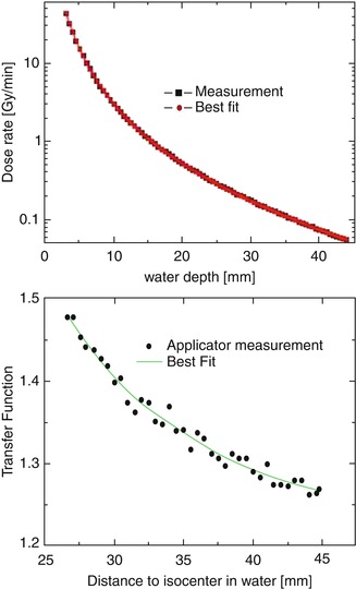
Fig. 4.1
Measurements of depth dose for probe only and applicator, with best fit lines overlaid
Baseline readings are also acquired during factory calibration for the IRM feedback monitor and output measured using the PAICH attachment. These are supplied with the calibration file and are used for comparison with PDA and PAICH checks performed before each treatment. Any small differences in the daily output are used to adjust the planned treatment time:
 (2)
(2)
Every 2 years, the user chamber and electrometer are returned to a standards laboratory to update the calibration factors for these instruments, and a new certificate is provided to the user. The air kerma factor from this certificate is then updated on the system at the same time as the replacement calibration file is installed.
During production, the isotropy of the applicators is measured using the water tank and values tabulated for each applicator size by removing the anisotropy due to the factory standard source:
 (3)
(3)
Further details on all these procedures can be found in Carl Zeiss Meditec AG (2011).
4.2 Commissioning
The extent of measurements undertaken for a commissioning process will depend on the local requirements, national regulations and personal interest. The minimum which has to be done before using the INTRABEAM system clinically is to perform the internal quality assurance tests defined by the system itself and to designate the radiation protection areas, which are described in more detail in the Chap. 5. In some countries it is necessary to verify the system using an independent method. In that case, some of the following approaches can be used. Further details on this topic can be found in a recent review article (Eaton 2012).
4.3 Independent Quality Assurance
4.3.1 Water Phantom
Zeiss offers a special water phantom (dimensions: 58 × 40 × 52 cm) to independently measure depth dose curves and isotropy of the XRS 4 in the local centre. The phantom consists of a water tank, filled with 6 l of water, and two cavities for placing a soft X-ray ionisation chamber (PTW type 23342) below or beside the XRS 4 (Fig. 4.2). A stepping mechanism allows a linear movement of the XRS 4 in three directions with positional accuracy of ±0.1 mm. Using the chamber cavity below the XRS 4 allows measurement of dose rates at different depths to confirm the calibration file of the system. To determine the isotropy, the XRS 4 can be rotated in steps of 45° around the vertical axis of the probe. Using the chamber cavity to the side of the XRS 4, dose rate measurements can be recorded at different source angles. All measurements can be done with and without an applicator. These measurements can be used to independently verify the calibration data, measured by the vendor.
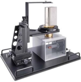
Fig. 4.2
Water phantom to measure depth doses and isotropy
Solid water-equivalent phantom materials may also be used to measure output at different depths (Härtl et al. 2009). Care must be taken, however, that the material is water-equivalent at low kilovoltage energies. The major source of error in these measurements will be positioning of the source and detector. An appropriate code of practice should be used to convert chamber readings into dose. The ionisation chamber should be linked to a national standard laboratory by direct calibration or local intercomparison against a secondary standard instrument. Intercomparison may be performed using the INTRABEAM system or a superficial unit of similar beam quality. Beam quality may be determined by measuring the half value layer, with the source collimated to approximate narrow beam geometry (Eaton and Duck 2010).
4.3.2 Film Measurement
An alternative approach to measure depth dose curves and isotropy of the XRS 4 with high spatial resolution is film dosimetry using radiochromic films, such as Gafchromic® films (ISP, New Jersey, USA). These are made by laminating an active layer between two polyester layers. Some advantages of these films are water resistance, tissue equivalence, wide detectable dose range, low energy dependence and the possibility of handling them in room light (Schneider et al. 2009a).
Gafchromic films have been used to determine the depth doses and spatial dose distributions of the INTRABEAM system, as shown in Fig. 4.3 (Schneider et al. 2009b). To analyse the isotropy, an applicator or probe shape was cut out from the film and the film was then placed around an applicator or the bare probe. This setup was sandwiched between two halves of solid water blocks, and irradiated. Afterwards it was scanned and evaluated according to standard local protocols.
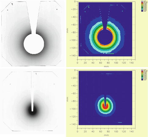
Fig. 4.3
Evaluation of isotropy using Gafchromic films
The verification of the depth dose curve is more difficult because the film has to be calibrated from pixel values (grey values) into dose. This can be done by irradiating a film along an extension of the axis of the probe. A profile on the scanned film along this axis gives a curve representing grey values as a function of depth. An exponential function can be fitted to that curve in Mathematica or Mathlab. In a second step the depth dose curve, which is calculated by the INTRABEAM terminal, can be fitted using another exponential function. Finally these two functions can be correlated to obtain an assignment of grey values to dose (Schneider et al. 2009b). However, in this approach some extra knowledge is needed to keep the compound error of the film-scanner system as low as possible (Schneider et al. 2009a; Andres et al. 2010).
4.3.3 TLD Measurement
Thermoluminescent dosimeters (TLDs) are small, portable, tissue equivalent and independent of dose rate or temperature, making them a useful addition to more accurate measurements with an ionisation chamber. Energy and dose dependence (supralinearity) necessitate calibration in a similar beam quality and dose level, but this can potentially be performed using a superficial therapy X-ray unit instead of the INTRABEAM system (Eaton and Duck 2010). Common clinical uses of TLDs in radiotherapy include checking the dose in vivo to normal tissues such as the eyes, and they have been also been used with INTRABEAM to measure skin doses during breast intraoperative radiotherapy (Eaton et al. 2012; Fogg et al. 2010).
Related posts:
 Targeted Intraoperative Radiotherapy: Concept and Review of Evidence in Breast Cancer
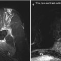 Follow-Up Findings in the Tumour Bed After IORT – What the Radiologist Needs to Know
 Quality Assurance and Training of Targeted Intraoperative Radiotherapy: Establishment of the TARGIT Academy
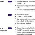 Treating Patients with TARGIT
 Intraoperative Photon Radiosurgery in Patients with Malignant Brain Tumours
 Radiobiology
Stay updated, free articles. Join our Telegram channel

Full access? Get Clinical Tree


