Radiographic Artifacts
Terry R. Yochum
Lindsay J. Rowe
INTRODUCTION
Since the early days of radiology, artifacts have appeared on radiographs. Actually, the first radiograph ever taken had an artifact present, a metallic ring on the patient’s hand. Artifacts are a common cause of repeat radiographs; they often occur in unexpected places, with many peculiar internal objects being detected. Without a complete history, many unusual artifactual shadows cannot be adequately identified. This chapter is presented in atlas format, using a pictorial review of various artifacts. Few radiologic interpretation texts show any artifacts, despite their common occurrence. This fact provided the impetus for us to add this atlas to the book. No attempt at an in-depth discussion of the production or physics behind radiographic artifacts is intended in this chapter because the technical aspects are thoroughly covered in other texts. (1,2,3,4)
Adherence to detail, especially in patient preparation, factor selection, positioning, and darkroom technique, using state-of-the-art equipment, will reduce the chances for producing artifacts.
TECHNICAL
 Figure 16-1 MOTION PROBLEMS. Lateral Lumbar. The image unsharpness was caused by patient movement. |
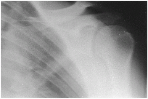 Figure 16-2 MOTION PROBLEMS. AP Shoulder. Patient motion blurred the final image of this shoulder. COMMENT: Motion is the greatest cause of image unsharpness on the final radiograph. (Courtesy of Felix G. Bauer, DC, DACBR(Hon), Sydney, Australia.) |
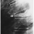
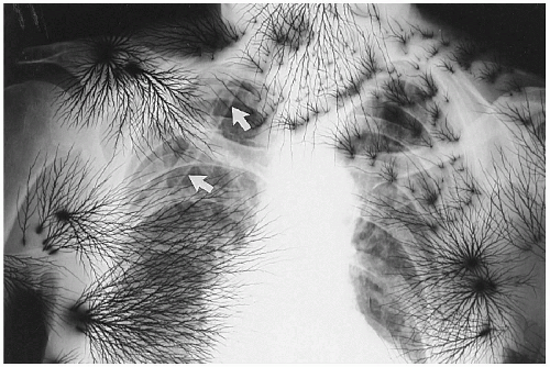 Figure 16-3 STATIC ELECTRICITY. PA Chest. This chest radiograph demonstrates a characteristic appearance of static electricity. Superimposed over the right upper thorax is a drainage tube (arrows). |
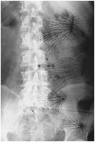 Figure 16-4 STATIC ELECTRICITY. AP Lumbar. The black streaks are static electricity markings on the radiograph. (Courtesy of Kenneth E. Yochum, DC, St. Louis, Missouri.) |
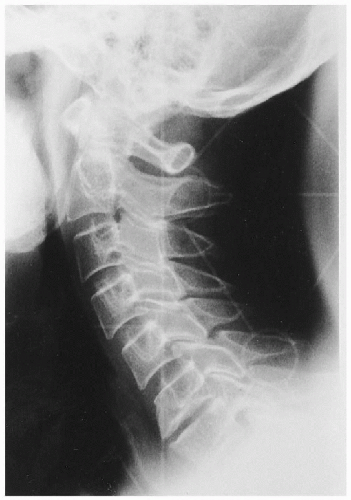
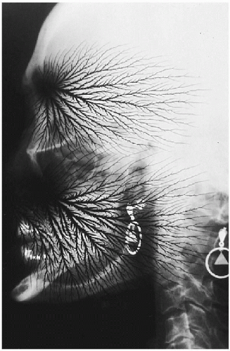 Figure 16-5 STATIC ELECTRICITY. Lateral Cervical Skull. The lightning-like black densities represent static electricity. COMMENT: This might make quite an advertisement for headaches. The metallic devices are earrings, which should always be removed when doing an x-ray examination of the skull or cervical spine. |
 Figure 16-6 TECHNICAL PROBLEMS. A. PA Chest. B. AP Lumbar. These radiographs demonstrate a wrinkling of the film emulsion because of shrinkage of the film base over many years in storage. This process has been called reticulation. On panel A, note the opacity of the right lung apex secondary to thoracopneumoplasty. |
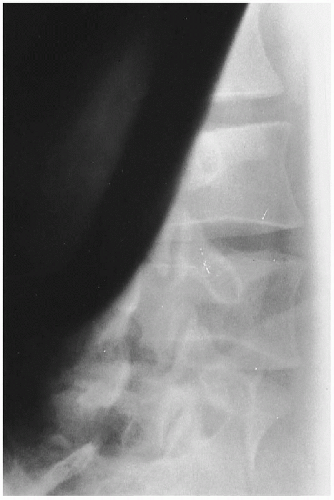 Figure 16-7 DEVELOPMENT PROBLEMS. Oblique Lumbar. The black area represents light exposure on the radiograph, which occurred sometime during the development process. |
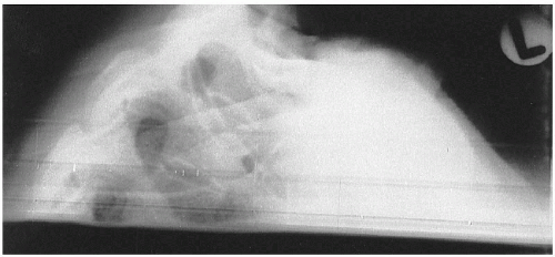 Figure 16-8 DEVELOPMENT PROBLEMS. Lateral Cervico-Thoracic. The lower portion of this radiograph was struck by light after the film was exposed to x-ray. COMMENT: This usually occurs as the film is entering the automatic processor and someone accidentally turns on the lights or opens the darkroom door too soon. |
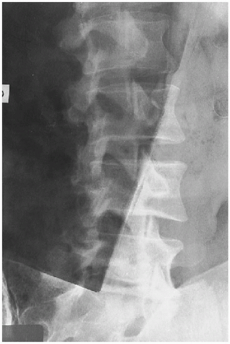 Figure 16-9 DEVELOPMENT PROBLEMS. Oblique Lumbar. The darkened area over this oblique lumbar radiograph is caused by two films overlapping in the development procedure. COMMENT: This may occur if insufficient time is allowed between feeding film through the automatic processor. |
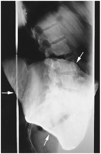 Figure 16-10 DEVELOPMENT PROBLEMS. Lateral Lumbar. The artifact on the radiograph represents an area where two radiographs became attached to each other in the manual developing process (arrows). This has been called a kissing defect. (Courtesy of Felix G. Bauer, DC, DACBR(Hon), Sydney, Australia.) |
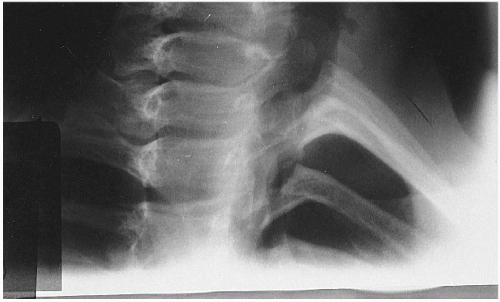 Figure 16-11 DEVELOPMENT PROBLEMS. Oblique Upper Thoracic. The gray area on the lower portion of this oblique radiograph was not developed because of the low level of developer solutions in the manual developing tank. |
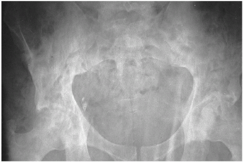 Figure 16-12 DEVELOPMENT PROBLEMS. AP Pelvis. These mottled streak-like densities occurred in the manual processing of this film from lack of proper agitation of the developer during the developing process. |
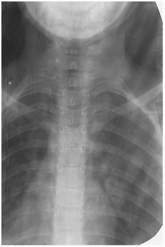 Figure 16-13 DEVELOPMENT PROBLEMS. AP Thoracic. The washed-out image was caused by exhausted developer solution. COMMENT: This occurs when the developer oxidizes or has been replenished with water rather than with fresh chemicals. (Courtesy of Felix G. Bauer, DC, DACBR(Hon), Sydney, Australia.) |
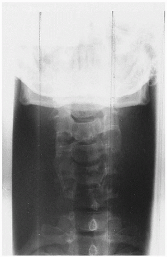 Figure 16-14 DEVELOPMENT PROBLEMS. AP Lower Cervical. The abnormal marks represent artifacts from dirty rollers in an automatic film processor. |
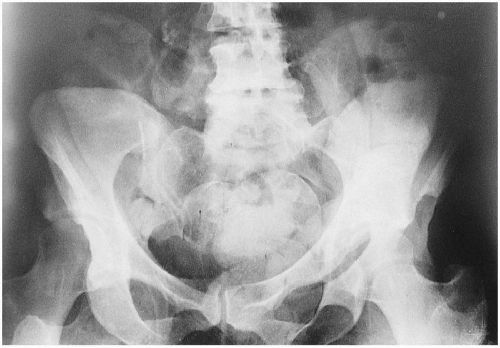
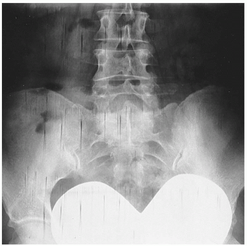 Figure 16-15 DEVELOPMENT PROBLEMS. AP Pelvis. The streaked marks represent a processing artifact from the crossover deflector guides in the automatic processor. The radiopaque heart-shaped structure is an ovarian gonadal shield that was positioned too low. |
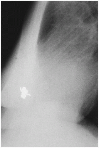 Figure 16-16 ENVIRONMENTAL PROBLEMS. Lateral Chest. This is a very unusual artifact; a bee was trapped inside the cassette, blocking the luminescence of the screen in this area. COMMENT: Other more common objects, such as slivers of paper, may cause a similar radiopaque artifact. We hope you have gotten the beeline on this case. (Courtesy of Richard T. Coade, MIR, DC, Kempsey, Australia.) |
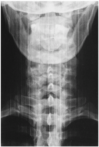 Figure 16-17 TECHNICAL PROBLEMS. AP Lower Cervical. The vertical radiopaque lines represent grid lines. This occurs when the grid does not move during the exposure because of a nonfunctioning bucky mechanism or a short exposure time. |
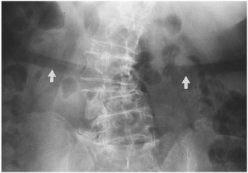 Figure 16-18 PATIENT PROBLEMS. Lumbar Spine. The broad radiolucent stripe across the abdomen (arrows) represents compression of the fat across the waistline by the patient’s undergarment. COMMENT: This can be avoided by having the patient remove all undergarments and wear an examination gown when being radiographed through the abdomen. (Courtesy of Donald M. Kuppe, DC, Denver, Colorado.) |
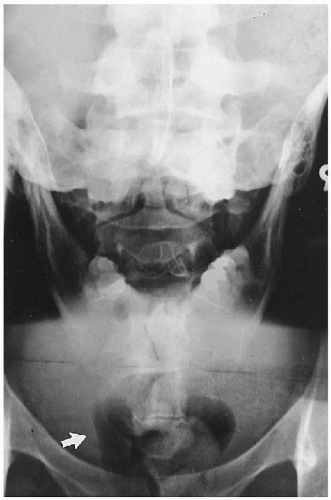 Figure 16-19 TECHNICAL PROBLEMS. AP Open Mouth and AP Pelvis. This film shows a double exposure of an AP open mouth and AP lumbosacral projection. COMMENT: Note the tampon above the pubic rami (arrow). (Courtesy of one of our students, Melbourne, Australia.) |
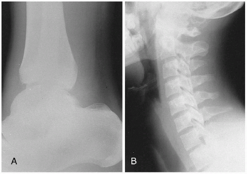 Figure 16-20 TECHNICAL PROBLEMS. A. Lateral Ankle. B. Lateral Cervical. Both films were underexposed. An increase in the milliamperage seconds (mAs) by approximately 50% would be necessary to obtain a diagnostic film; the kilovoltage peak (kVp) should not be altered. |
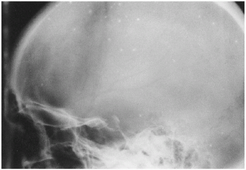 Figure 16-21 TECHNICAL PROBLEMS. Lateral Skull. The white, circular areas scattered throughout the skull depict screen artifacts. These represent areas within the screen where the phosphor is no longer adequate and illumination is not occurring properly. COMMENT: It is time to replace these screens. |
 Figure 16-22 TECHNICAL PROBLEMS. A. AP Hip. B. AP Lumbar. The blurred appearance of the bony trabeculae in the area of the greater trochanter is the result of poor film-screen contact. Similar blurred areas are seen scattered throughout the lumbar spine, as a result of underlying poor film-screen contact. (Courtesy of John A. M. Taylor, DC, DACBR, Seneca Falls, New York.) |
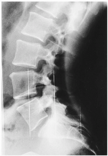 |
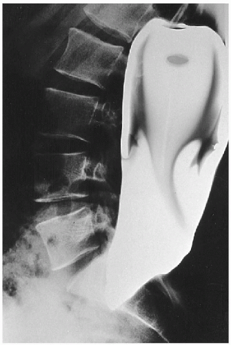 Figure 16-24 DEVELOPMENT PROBLEMS. Lateral Lumbar. This is a large kissing artifact, which occurs when two films stick together during the developing process. (Courtesy of Felix G. Bauer, DC, DACBR(Hon), Sydney, Australia.) |
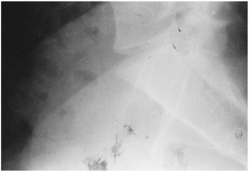 Figure 16-25 TECHNICAL PROBLEMS. Lateral Lumbosacral. The blackened, smudge-like areas on the lower aspect of the film represent fingerprints. COMMENT: During the development process the film should be handled at the corners; otherwise such fingerprint artifacts will occur. (Courtesy of John A. M. Taylor, DC, DACBR, Seneca Falls, New York.) |
 |
THERAPEUTIC
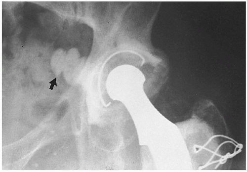 Figure 16-28 POST-JOINT REPLACEMENT. AP Hip. This patient has undergone a hip joint replacement procedure from which some of the acrylic bone cement (arrow) leaked into the pelvic basin. (Courtesy of Richard W. Jackson, DO, St. Louis, Missouri.) |
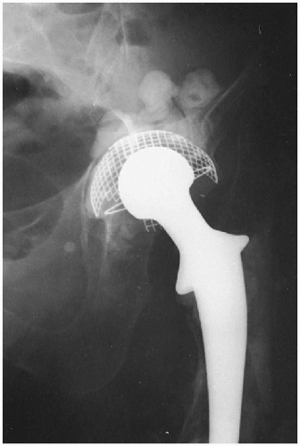 Figure 16-29 POST-JOINT REPLACEMENT. AP Hip. This patient has had a total hip replacement with a metallic prosthesis. (Courtesy of John M. Bauler, DC, Clovis, New Mexico.) |
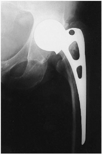 Figure 16-30 POST-JOINT REPLACEMENT. AP Hip. This is a Moore’s hip prosthesis. |
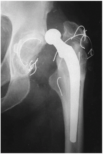 Figure 16-31 POST-JOINT REPLACEMENT. Hip. This patient’s prosthetic hip has luxated and some of the wires have broken. |
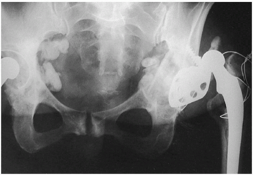 Figure 16-32 POST-JOINT REPLACEMENT. AP Pelvis. This elderly female dislocated her hip prosthesis after a recent fall. (Courtesy of David B. Taylor, DC, Joliet, Illinois.) |
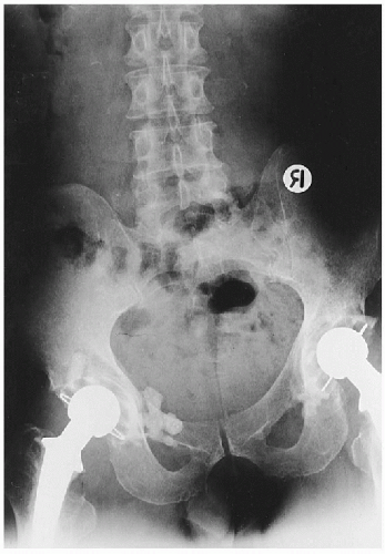 Figure 16-33 POST-JOINT REPLACEMENT. AP Pelvis. This patient has had a bilateral total hip replacement. The radiopaque densities adjacent to the left acetabulum represent leaking of acrylic bone cement. |
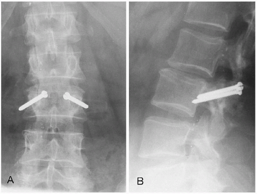 Figure 16-34 POST-ARTHRODESIS. A. AP Lumbar. B. Lateral Lumbar. This patient underwent arthrodesis with threaded screws through the inferior facets of L2 and into the pars and pedicles of L3. |
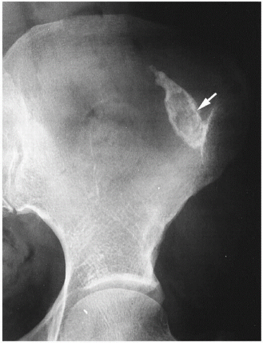 Figure 16-35 POST-INJECTION. AP Hip. This calcified injection granuloma (arrow) is in the soft tissues of the buttocks. |
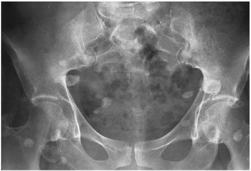 Figure 16-36 POST-INJECTION. AP Pelvis. The circular calcific densities represent sites of vitamin B12 injections in the buttocks (injection granulomas). |
 Figure 16-37 POST-INJECTION. AP Pelvis. There are two forms of artifacts on this pelvic radiograph. The metallic densities are the sequelae of heavy metal injections for syphilis (arrow). The calcific cystic densities are injection granulomas (arrowhead). (Courtesy of Richard A. Bergeron, DC, Golden, Colorado.) |
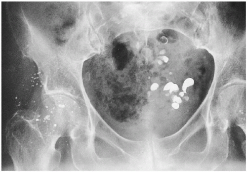 Figure 16-38 POST-INJECTION. AP Pelvis. The radiopaque densities about the hip joint and in the buttocks represent injection sites with metallic residuals. The radiopaque densities in the pelvic basin represent residual barium in diverticula of the sigmoid colon. (Courtesy of Beverly L. Harger, DC, DACBR, Portland, Oregon.) |
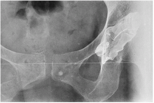 Figure 16-39 SURGICAL MATERIAL. AP Pelvis. The radiopaque density represents a wire mesh substance called tantalum, a non-corrosive, malleable metal used for making prosthetic appliances. |
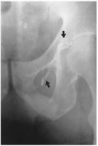 Figure 16-40 SURGICAL MATERIAL. AP Pelvis. The metallic densities (arrows) represent residual surgical material from repair of an inguinal hernia. |
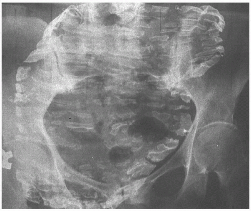 |
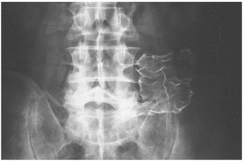 Figure 16-42 SURGICAL MATERIAL. AP Pelvis. This is tantalum wire mesh, which was used to repair abdominal hernias years ago. |
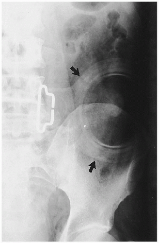 Figure 16-43 COLOSTOMY BAG. AP Hip. This patient had his colon removed for ulcerative colitis; the artifact present is a colostomy bag (arrows). |
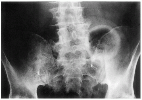 Figure 16-44 BLADDER BAG. AP Pelvis. The circular radiopaque density represents a bladder bag. (Courtesy of Paul E. Price, DC, Erie, Denver, Colorado.) |
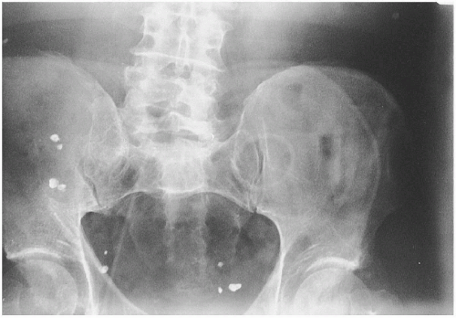 |
 Figure 16-46 CANCER TREATMENT. A. AP Pelvis. B. Lateral Pelvis. These metallic artifacts are radium implants used in the treatment of carcinoma of the cervix. |
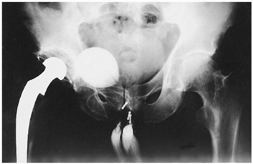 Figure 16-47 IMPOTENCE PUMP. AP Hip. This male patient has a metallic hip prosthesis. The device seen in the groin and scrotal region is a surgically implanted mechanical pump used in cases of impotence. (Courtesy of Kenneth E. Yochum, DC, St. Louis, Missouri.) |
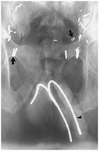 |
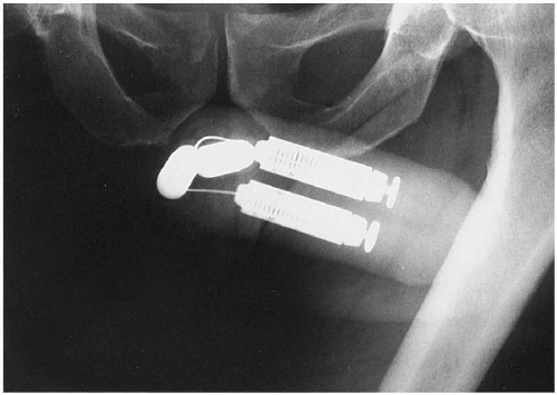 Figure 16-49 PENILE IMPLANT. AP Pelvis. This patient has a mechanical impotence pump within the penis. (Courtesy of Jerry Collyer, RT(R), Denver, Colorado.) |
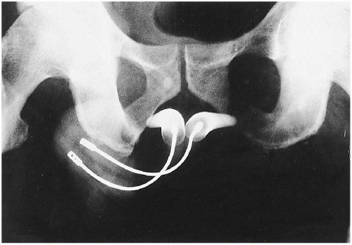 |
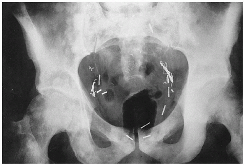 Figure 16-51 SURGICAL MATERIAL. AP Pelvis. The metallic surgical clips are the densities left after this patient had a prostatectomy for carcinoma. Note the typical blastic metastatic lesions scattered throughout the pelvis and femora. (Courtesy of Gary E. Spears, DC, Denver, Colorado.) |
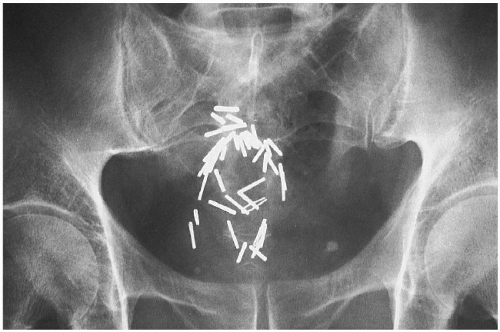 Figure 16-52 SURGICAL MATERIAL. AP Pelvis. This 60-year-old male patient has had a colonic resection for carcinoma of the sigmoid colon. The metallic clips are the results of the surgery. (Courtesy of Donald M. Kuppe, DC, Denver, Colorado.) |
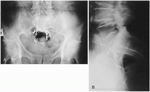 |
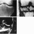
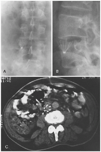 Figure 16-54 IVC UMBRELLA FILTER. A. AP Lumbar. B. Oblique Lumbar. The metallic artifact represents an umbrella filter in the inferior vena cava (IVC), used to catch blood clots. C. CT, Axial Abdomen. This CT scan of another patient shows an IVC filter in place. COMMENT: These filters are used in patients with a long-standing history of thrombophlebitis. (Panels A and B courtesy of Nathaniel S. Wirt, PhD, DC, and Gary M. Guebert, DC, DACBR, St. Louis, Missouri. Panel C courtesy of Steven P. Brownstein, MD, Springfield, New Jersey.) |
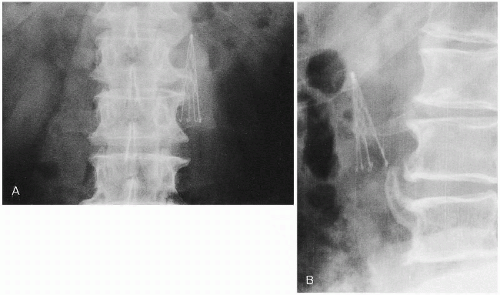 Figure 16-55 IVC UMBRELLA FILTER. A. AP Lumbar. B. Lateral Lumbar. This metallic umbrella filter is placed in the inferior vena cava to capture emboli from the lower extremities in patients with thrombophlebitis. (Courtesy of John C. Slizeski, DC, Denver, Colorado.) |
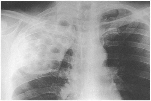 Figure 16-56 PLOMBAGE PROCEDURE. PA Chest. A right upper lobectomy for tuberculosis has been performed; the tissue was replaced with implanted lucite balls, referred to as a plombage procedure. COMMENT: This technique was employed to reduce mediastinal shift and maintain anatomic relationships within the chest. (Courtesy of William E. Litterer, DC, DACBR, Fellow, ACCR, Elizabeth, New Jersey.) |
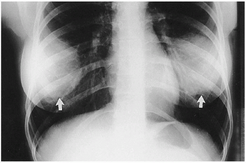 Figure 16-57 SILICONE IMPLANTS. PA Chest. The shadows of both breasts appear very dense because of the presence of silicone implants (arrows). |
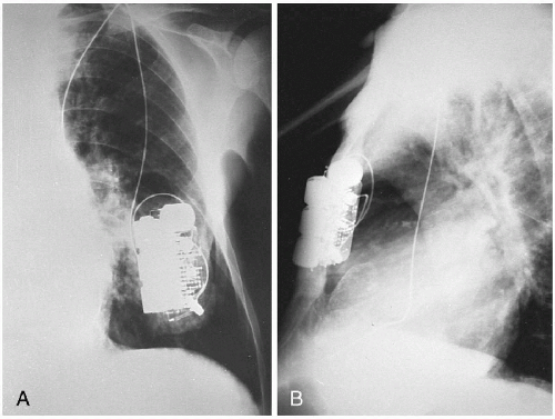 |
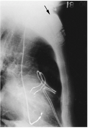 Figure 16-59 CARDIAC PACEMAKER. PA Chest. There is a cardiac pacemaker (arrow) in the subcutaneous tissues of the anterior chest wall. The string-like radiopacities represent the cardiac leads from the pacemaker. (Courtesy of Donald Resnick, MD, San Diego, California.) |
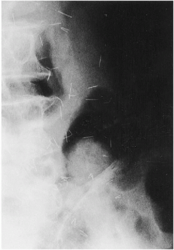 Figure 16-60 ACUPUNCTURE NEEDLES. AP Lumbar. Observe the multiple radiopaque densities scattered throughout the subcutaneous tissues. These represent broken-off acupuncture needles in a patient who has had many acupuncture treatments. (Courtesy Ian Chen, MD, San Francisco, California.) |
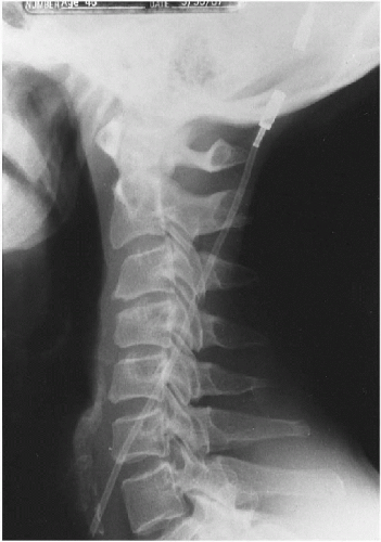 Figure 16-61 CSF SHUNT. Lateral Cervical. A plastic tube can be seen passing obliquely within the soft tissues of the neck from the skull into the thorax and eventually to the abdominal cavity. This is referred to as a ventriculoperitoneal shunt, used to manage high-pressure hydrocephalus by redirecting cerebrospinal fluid produced in the lateral ventricles of the brain into the peritoneal cavity where it is resorbed. |
 Figure 16-62 SURGICAL MATERIAL. A. Presurgery AP Hip. This young football player was tackled, which caused a fracture of the acetabulum and dislocation of the femur. B. Postsurgery AP Hip. The surgical correction is shown, with multiple screw fixations. (Courtesy of James C. Wagner, DC, Denver, Colorado.) |
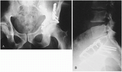 Figure 16-63 FRACTURED ACETABULUM: SURGICAL MATERIAL. A. AP Hip. B. Lateral Lumbar. This patient was in an automobile accident and sustained a fractured acetabulum and ilium. The surgical screw fixation was successful in the treatment of this patient. COMMENT: Patients with these types of injuries are often destined to develop premature degenerative osteoarthritis of the hip as a post-traumatic sequela. |
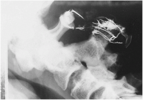 Figure 16-64 TRANSVERSE LIGAMENT TEAR: SURGICAL MATERIAL. Lateral Cevical Flexion. This patient had a history of atlantoaxial instability owing to disruption of the transverse ligament after a motor vehicle accident. This was surgically stabilized with atlantoaxial wires (Gallie’s procedure). Seen here, the wires have since broken, rendering the upper cervical complex once again unstable. (Courtesy of Richard Edmonds, BAppSc (Chiro), Melton, Australia.) |
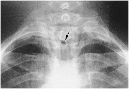 Figure 16-65 STOMA: SURGICAL MATERIAL. PA Chest. There is a peculiar circular radiolucent area seen at the T2-T3 level (arrow). This represents the stoma in a patient who has had surgery for cancer of the throat. (Courtesy of George E. Springer, DC, Clearwater, Florida.) |
 |
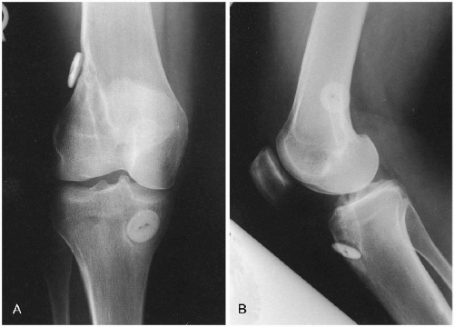 Figure 16-67 SURGICAL MATERIAL. A. AP Knee. B. Lateral Knee. The radiopaque button-like densities represent the areas of securing the surgical synthetic replacement for the anterior cruciate ligament. Notice that there is a curvilinear density tracking through the bone, making a passageway for the reconstructed synthetic anterior cruciate ligament. (Courtesy of Tyrone Wei, DC, DACBR, Portland, Oregon.) |
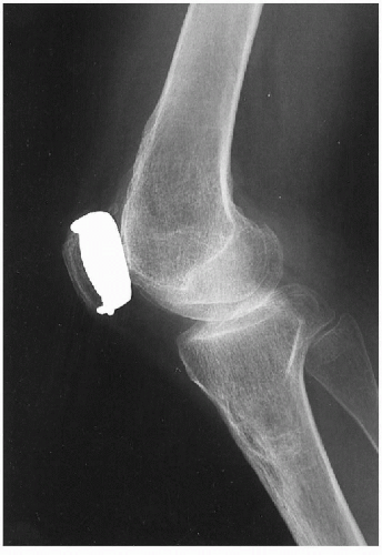 Figure 16-68 PROSTHETIC PATELLA. Lateral Knee. This patient had a previous fracture of the patella with subsequent retropatellar degenerative disease, creating an unstable joint. A prosthetic metallic patella has been inserted to stabilize the knee. (Courtesy of William E. Litterer, DC, DACBR, Fellow, ACCR, Elizabeth, New Jersey.) |
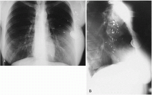 Figure 16-69 MASTECTOMY AND BREAST RECONSTRUCTION. A. PA Chest. B. Lateral Chest. The multiple surgical sutures and circular artifacts are the result of a partial mastectomy and breast reconstruction. |
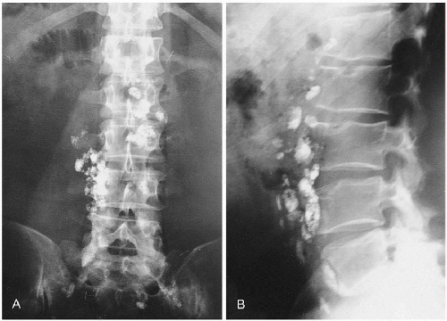 Figure 16-70 HODGKIN’S LYMPHOMA. A. AP Abdomen. B. Lateral Abdomen. There is residual contrast from a recent lymphangiogram present in the retroperitoneal lymph nodes in a young patient who has been diagnosed with Hodgkin’s lymphoma. Retained contrast material in these lymph nodes for an extended period suggests underlying organic pathology. (Courtesy of Richard M. Nuzzi, DC, Boulder, Colorado.) |
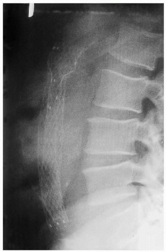 Figure 16-71 SURGICAL MATERIAL: ABDOMINAL AORTIC ANEURYSM. Lateral Abdomen. Observe the calcified abdominal aortic aneurysm. Treatment of the aneurysm was performed by inserting a graft to lessen the likelihood of rupture. This patient has done well postsurgically. (Courtesy of Anne P. Odenweller, DC, Baton Rouge, Louisiana.) |
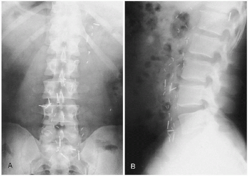 Figure 16-72 HODGKIN’S LYMPHOMA. A. AP Abdomen. B. Lateral Abdomen. There are multiple scattered metallic surgical clips in the area of the retroperitoneal lymph nodes from T12 through the lumbosacral junction. These represent the sequelae from surgical treatment for Hodgkin’s lymphoma. (Courtesy of Richard L. Green, DC, Boston, Massachusetts.) |
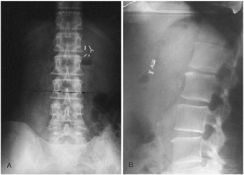 Figure 16-73 CHOLECYSTECTOMY CLIPS. A. AP Abdomen. B. Lateral Abdomen. Observe the cholecystectomy clips in the right upper quadrant of the abdomen. (Courtesy of Ralph E. Brewer, DC, Denver, Colorado.) |
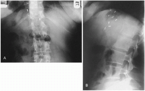 Figure 16-74 VAGOTOMY CLIPS. A. AP Abdomen. B. Lateral Abdomen. There are surgical clips close to the stomach in the left upper quadrant of the abdomen near the midline. These represent vagotomy clips in a patient who had a history of chronic ulcers. (Courtesy of George E. Springer, DC, Clearwater, Florida.) |
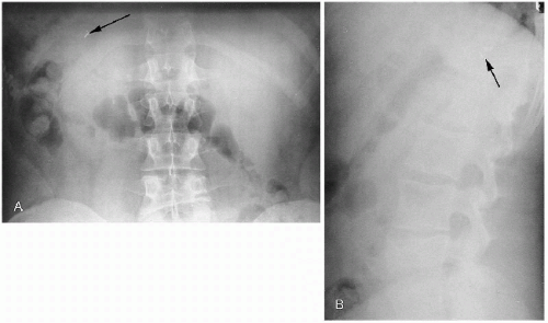 Figure 16-75 SPLENECTOMY CLIPS. A. AP Abdomen. B. Lateral Abdomen. There are surgical clips in the posterior aspect of the left upper quadrant of the abdomen (arrows). These represent splenectomy clips. There is an old fracture of the L4 vertebral body. COMMENT: This patient underwent severe trauma to the spine and abdomen with a ruptured spleen, which led to splenectomy. (Courtesy of George E. Springer, DC, Clearwater, Florida.) |
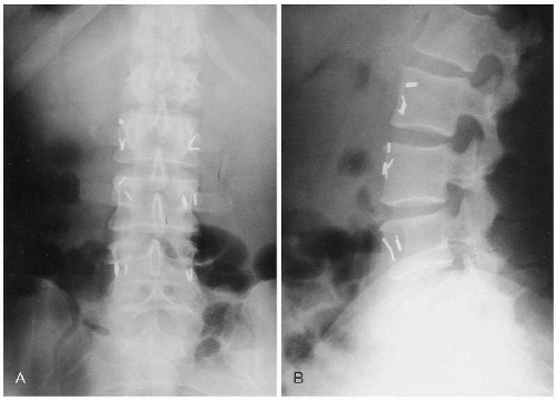 Figure 16-76 SYMPATHECTOMY CLIPS. A. AP Lumbar. B. Lateral Lumbar. Surgical clips are present bilaterally from L3 through S1. These represent the remnants of a sympathectomy, which was performed on this patient for severe Raynaud’s phenomenon. (Courtesy of Eugene Ver Meer, DC, Denver, Colorado.) |
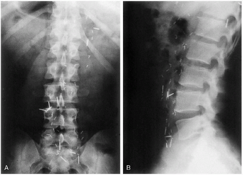 Figure 16-77 HODGKIN’S LYMPHOMA. A. AP Lumbar. B. Lateral Lumbar. There are bilateral surgical metallic clips in this patient who has Hodgkin’s lymphoma. (Courtesy of Richard L. Green, DC, Boston, Massachusetts.) |
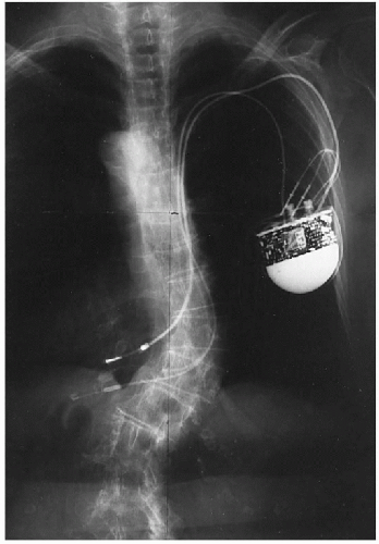 Figure 16-78 CARDIAC PACEMAKER. PA Chest. There is a cardiac pacemaker present in the subcutaneous tissues of the anterior chest wall with appropriate cardiac leads in place. (Courtesy of Paul Van Wyk, DC, Denver, Colorado.) |
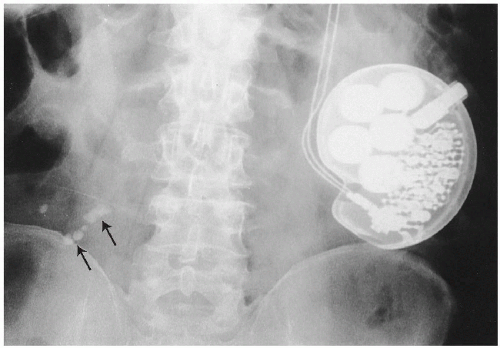 Figure 16-79 CARDIAC PACEMAKER. AP Lumbar. There is a cardiac pacemaker present in the subcutaneous tissues of the abdomen. Of incidental notation are some calcified abdominal lymph nodes present in the lower abdomen (arrows).
Related posts:Stay updated, free articles. Join our Telegram channel
Full access? Get Clinical Tree
 Get Clinical Tree app for offline access

|