mm and a mean DICE coefficient of  were obtained when comparing the computed segmentations with ground truth segmentations. These results are highly competitive when compared to the results of earlier presented methods.
1 Introduction
Segmentation of organs in the human body is one of the most important problems in medical image computing. The challenges associated with medical image segmentation, and what is causing further research to be motivated within the domain, include low contrast between organ of interest and surrounding tissues, imaging artifacts, image noise and anatomical variation. There exists many different approaches for how a segmentation problem can be solved. Proposed methods vary from simple thresholding to more elaborate methods using e.g. probabilistic shape models. The relevance of the different approaches depend on the specific organ to segment along with the employed imaging modality. This work is focused on the segmentation of the vertebrae in the spine as imaged by computed tomography (CT).
The spinal column forms an important support structure in the human body and consists of the vertebral bones, seven cervical, twelve thoracic and five lumbar vertebrae. As such, the vertebrae form an important part of the diagnosis, treatment planing and the understanding of various conditions affecting the spine. Thus, an accurate segmentation of the vertebrae is of relevance in several medical applications. Segmentation of the vertebrae is challenging, mainly due to shape variation and neighboring structures of similar intensity (e.g. other vertebrae and/or tissues).
There already exists a number of proposed methods for segmentation of the vertebrae in the spine from CT data. For example, in [9], Kim and Kim proposed a fully automatic method based upon deformable fences for separating lumbar vertebra in the spinal column. Klinder et al. presented in [10] a method, commonly referred to as the current state-of-the-art for both identification and segmentation of an arbitrary set of vertebrae. The method is based upon spinal curve extraction with vertebra detection followed by vertebra identification and segmentation based upon shape models. Ma et al. [13] also proposed a method capable of both segmentation and identification, but only for the thoracic vertebrae. Their method is based upon training bone-structure edge detectors along with coarse-to-fine registration of a deformable model. Other and more recently proposed methods are found in [8, 12, 14], where the authors of the first work propose an improved level set method based upon edge- and region-information. The authors of the second work also propose to use a level set method but including the Willmore flow and where the third work presents a method based on a multi-vertebrae anatomical shape and pose model. Note that all of these three methods were only evaluated segmenting the lumbar vertebrae.
In this paper, a method based upon atlas-based segmentation is proposed and evaluated. Atlas-based segmentation is a method where image registration between an atlas image and a target image is performed and where the predefined labels of the atlas are used for segmenting the region of interest in the target image. Atlas-based segmentation has found its way into many application domains within medical imaging and in particular for segmentation of various structures in the brain in magnetic resonance imaging [2]. In atlas-based segmentation, it is common to use a number of atlases that are registered towards a target image and where label fusion is used to derive a single segmentation from the labels of the registered atlases.
The method, described in this paper, benefits from the knowledge of previous work in term of preprocessing (vertebral pose estimation), spine registration (non-rigid registration based on phase-difference and the use of graphics processing units) and label fusion (majority voting), and combines these into an effective pipeline providing automatic and accurate segmentation of both lumbar and thoracic vertebrae in the spinal column.
2 Methods
The method used in this work for vertebrae segmentation is inspired and to a large extent based upon the work presented in [6, 7], although some components have changed and others have been added. This has been done in order to improve the performance but mainly since the work in [6, 7] was targeted at scoliotic spines. The most notable differences are the use of multiple gray-level atlases, instead of a single binary model in the registration step, and the subsequent use of label fusion. The employed method consists of a preprocessing step, where an approximate position and rotation (pose) of each vertebra in the target data set and in the atlases is estimated. The results from the preprocessing are used to obtain an initial alignment between the atlases and the target data set. The preprocessing step is followed by a registration step, where each atlas is registered to the target data set. The labels of the registered atlases are combined to a single label volume using label fusion to form the segmentation of the spine as imaged in the target data set. A graphical overview of the method is provided in Fig. 1.
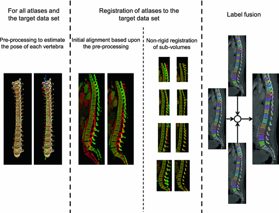
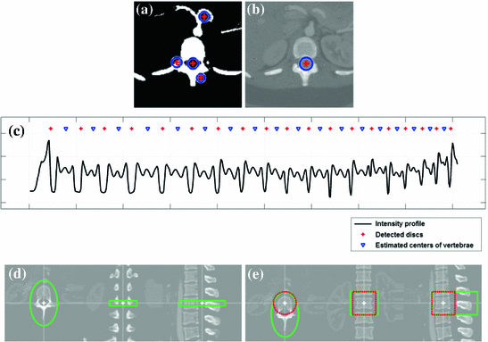

Fig. 1
An overview of the method used for segmentation of the thoracic and lumbar vertebrae in the spine. In the middle section of this figure, the green-colored spine refers to the atlas and the red-colored to the target data set (Color figure online)

Fig. 2
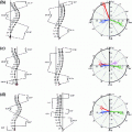
The preprocessing steps starts with a seed point detection (a) for the tracking of the spinal canal (b). Given the spinal canal, an intensity profile running through the vertebrae is sampled and analyzed to detect the position of the discs and implicitly the mid-axial slices of the vertebra (c). The mid-axial slices with initial estimates of the axial vertebral rotation (d) provide input to the final pose estimations (e). Note that the marked regions in (d) and (e) correspond to the volumes used for symmetry assessment
2.1 Preprocessing
The preprocessing consists of the following sub-steps:
1.
Spinal canal tracking—Seed points for the spinal canal are detected using the Hough transform on a thresholded axial image in the middle of the image volume. A growing and moving circle is used to detect the center of the spinal canal, i.e. a small circle is initialized at a given seed point and the circle grows until it hits bone upon which it tries to move away from the bone, in order to grow further. This growing and moving process is iterated until the circle either cannot grow or move anymore without hitting bone. The growing and moving circle process is repeated for each image as the spinal canal is tracked in both the cranial and the caudal direction. A minimum and a maximum size of the circle is defined along with exit criteria to ensure that the tracking stops as the sacrum or the top cervical vertebrae are reached. A spline curve is fitted to the extracted centerline in order to obtain a smooth curve. Seed point detection and tracking of the spinal canal are depicted in Fig. 2a, b.
2.
Disc detection—Given that the vertebrae are located anterior to the spinal canal, an intensity profile, running through the vertebrae, is sampled and filtered with quadrature filters of varying center frequencies. Given the distinctive pattern of the intensity profile, the filtered intensity profiles can be used to detect the position of the discs, simply by searching for peaks. Some heuristics have been added to remove false positive peaks. An example of the characteristic intensity profile is given in Fig. 2c.
3.
Initial vertebral rotation estimation—In an image slice located between the detected discs, an initial axial vertebral rotation is estimated based upon minimizing an error measure for assessing the symmetry between two halves of an image (left and right halves). The center of rotation is set to the center-point of the spinal canal and the orientation of the image plane is given by the tangent of the spinal canal centerline. For a more robust rotation estimation, not just a single image is used but a number of images. The volume enclosed by the green marking in Fig. 2d, refers to region for which the lateral symmetry is maximized.
4.
Vertebra position and rotation estimation—The two previous steps provide an initial estimate of the position and the orientation of each vertebra. To improve this estimate, an error measure is defined with six parameters ![$$ [x,y,z] $$](/wp-content/uploads/2016/10/A331518_1_En_5_Chapter_IEq3.gif) and
and ![$$ [\theta _X, \theta _Y, \theta _Z] $$](/wp-content/uploads/2016/10/A331518_1_En_5_Chapter_IEq4.gif) , defining the vertebra center-point and the rotation of the vertebra. The error measure is defined to assess the symmetry across various half-planes. The optimal parameters are found using Powell’s method, as provided by the MATLAB package iFit [4]. This step is similar to the method used in [15] for estimating the center-point and the orientation of each vertebra in the spine. The green marked region, in Fig. 2e, is used to assess the lateral symmetry, and where the red marked region is used to assess anterior-posterior symmetry and the inferior-superior symmetry.
, defining the vertebra center-point and the rotation of the vertebra. The error measure is defined to assess the symmetry across various half-planes. The optimal parameters are found using Powell’s method, as provided by the MATLAB package iFit [4]. This step is similar to the method used in [15] for estimating the center-point and the orientation of each vertebra in the spine. The green marked region, in Fig. 2e, is used to assess the lateral symmetry, and where the red marked region is used to assess anterior-posterior symmetry and the inferior-superior symmetry.
![$$ [x,y,z] $$](/wp-content/uploads/2016/10/A331518_1_En_5_Chapter_IEq3.gif) and
and ![$$ [\theta _X, \theta _Y, \theta _Z] $$](/wp-content/uploads/2016/10/A331518_1_En_5_Chapter_IEq4.gif) , defining the vertebra center-point and the rotation of the vertebra. The error measure is defined to assess the symmetry across various half-planes. The optimal parameters are found using Powell’s method, as provided by the MATLAB package iFit [4]. This step is similar to the method used in [15] for estimating the center-point and the orientation of each vertebra in the spine. The green marked region, in Fig. 2e, is used to assess the lateral symmetry, and where the red marked region is used to assess anterior-posterior symmetry and the inferior-superior symmetry.
, defining the vertebra center-point and the rotation of the vertebra. The error measure is defined to assess the symmetry across various half-planes. The optimal parameters are found using Powell’s method, as provided by the MATLAB package iFit [4]. This step is similar to the method used in [15] for estimating the center-point and the orientation of each vertebra in the spine. The green marked region, in Fig. 2e, is used to assess the lateral symmetry, and where the red marked region is used to assess anterior-posterior symmetry and the inferior-superior symmetry.Note that all atlases and the target data set are processed with this preprocessing step. Parameters used in the preprocessing step were fixed for the processing of all data sets but were empirically determined based upon initial processing of one of the data sets.
2.2 Initial Alignment
The estimated poses are used for establishing an initial alignment between the vertebrae of the atlases and the vertebrae of the spine in the target data set. The alignment is achieved by translating one atlas according to the mean displacement between the respective vertebrae in the data sets, i.e. the displacement between vertebrae T1 in the target and in the atlas data sets, and between T2 in the target and in the atlas data sets and so forth. Furthermore, a scaling of the atlas data sets is included by using the ratio between the two T1-L5 distances in the target and the atlas data sets.
2.3 Atlas-Based Registration
Given the initial alignment between the vertebrae of the target data set and an atlas, the vertebrae are then processed in groups of five, starting from the caudal end of the spine, i.e. L5-L1, L1-T9, T9-T5, T5-T1. A sub-volume is extracted from both the target data set and the atlas at hand, containing the vertebrae to be registered along with any surrounding vertebrae. After the initial alignment, a non-rigid registration step is applied, minimizing the voxel-wise local phase-difference [11], according to

where  is the local structure tensor and
  the local phase-difference in orientation
  . For computational performance, an implementation of the non-rigid registration algorithm on graphics processing units has been used [5]. The finally computed transformation is used to deform the atlas onto the target data set, and, thus, the labels of the deformed atlas provide a segmentation of the vertebrae in the target data set. This process is repeated for each available atlas.

(1)
 is the local structure tensor and
  the local phase-difference in orientation
  . For computational performance, an implementation of the non-rigid registration algorithm on graphics processing units has been used [5]. The finally computed transformation is used to deform the atlas onto the target data set, and, thus, the labels of the deformed atlas provide a segmentation of the vertebrae in the target data set. This process is repeated for each available atlas.
2.4 Label Fusion
The final step is to merge the labels of the deformed atlases into a single label volume. In this case, a straight forward majority voting has been employed for label fusion, although more refined methods for label fusion are available, e.g. STAPLE [16].
Stay updated, free articles. Join our Telegram channel

Full access? Get Clinical Tree


