Fig. 1
Images contain an arrow shape with different orientations. By finding the matched feature points (marked as red points), one is able to estimate the rotation angle and translation of a rigid transformation for registering the images
In the area based image registration methods, instead of feature points, image regions are considered. In other words, all image pixels within a region of interest are regarded as one feature “point”. Typically, parameters of certain transformation model in the area based image registration are determined based on a predefined cost function. The most commonly adopted cost functions include Pearson correlation coefficient for modeling linear relationship between intensities of images to be registered and mutual information for modeling their non-linear relationship [15].
The image registration methods can also be classified as either parametric image registration or non-parametric image registration based on the transformation model used in the registration. The advantage of parametric image registration methods is their high computational efficiency. In particular, linear parametric transformation models used in image registration include rigid transformation, affine transformation, and projection mapping, while Thin Plate Spline (TPS) and Free-Form Deformations (FFD) are typically adopted as non-linear parametric transformation models in image registration [19, 20].
Since the deformation modeled by a parametric model typically has low degrees of freedom, non-parametric image registration methods are often used for registering images with diffuse, local differences, e.g., brain images [21]. Among the non-parametric image registration methods, Thirion’s Demons algorithm [22] is one well-known method. The Demons algorithm is derived from the optical flow equation [23], and the deformation vector for each pixel is formulated as
 is the deformation vector at each pixel
  ,
,  and
and  are floating and target images, and
  is a small tolerance to improve the solution’s numerical stability. The Demons algorithm achieves image registration in an iterative way. In particular, at each iteration step, deformation vectors for all pixels are calculated and regularized by a Gaussian filter, and then the resulting deformation vectors are added to an accumulated deformation field. At the end, the accumulated deformation field is used to warp
  to
to  .
.


Get Clinical Tree app for offline access
 is the deformation vector at each pixel
  ,
,  and
and  are floating and target images, and
  is a small tolerance to improve the solution’s numerical stability. The Demons algorithm achieves image registration in an iterative way. In particular, at each iteration step, deformation vectors for all pixels are calculated and regularized by a Gaussian filter, and then the resulting deformation vectors are added to an accumulated deformation field. At the end, the accumulated deformation field is used to warp
  to
to  .
.
Fig. 2
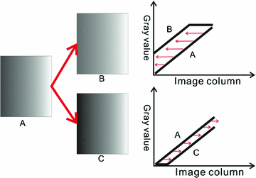
Illustration of the Demons. Left images with a ramp structure of gray values. Right top intensity profile and the deformation vectors of pixels at each column for registering image A to image B. Right bottom intensity profile and the deformation vectors of pixels at each column for registering image A to image C
Figure 2 illustrates how the deformation vector is calculated by Eq. (1) for registering one image (denoted by A) to two different images (denoted by B and C). Each image contains a different ramp structure of gray values. For registering image A to image B, since the gray value of each column of A is smaller than the corresponding column in B,  is negative according to the Eq. (1). Therefore, the directions of deformation vectors for each column of A is opposite to the directions of image gradient of B as shown in the right top of Fig. 2. On the contrary, for registering image A to image C, the deformation vectors and the image gradient of C have the same direction since the gray value of each column of A is bigger than the corresponding column in C, as shown in the right bottom of Fig. 2.
 is negative according to the Eq. (1). Therefore, the directions of deformation vectors for each column of A is opposite to the directions of image gradient of B as shown in the right top of Fig. 2. On the contrary, for registering image A to image C, the deformation vectors and the image gradient of C have the same direction since the gray value of each column of A is bigger than the corresponding column in C, as shown in the right bottom of Fig. 2.
The Demons algorithm has been improved for achieving better accuracy and higher efficiency in different ways and validated in different applications [22, 24–70]. Among its improved versions, the Diffeomorphic Demons algorithm has been widely adopted in the registration of brain images [65]. Since deformation vectors are projected onto the Lie groups by exponential maps, the Diffeomorphic Demons algorithm is able to obtain a diffeomorphic deformation field, i.e., no folding and invertible. This algorithm has also been used in groupwise image registration methods that are built upon pairwise image registration [8, 11, 71].
The pairwise image registration has been extended for registering multiple images using different strategies, referred to as groupwise image registration. The remainder of this chapter reviews representative groupwise image registration methods, including the congealing method, the direct pairwise image registration based and the intermediate templates based groupwise image registration. In particular, graph based groupwise image registration methods are introduced as special cases of the intermediate template based groupwise image registration.
3 Groupwise Image Registration Using Congealing
The congealing method was first proposed by Miller [72] for the task of image classification, and then was adopted for groupwise image registration [73]. Parametric deformation models are typically used in the congealing based groupwise image registration, including affine transformation and B-spline deformation [12, 73]. The congealing method in conjunction with the Diffeomorphic Demons algorithm has also been adopted in fMRI data registration [74].
In the congealing method, no template is required. The similarity among images to be registered is measured by the sum of pixel wise (voxelwise) entropies across the whole image space

where x is the spatial location of a pixel, n is the number of pixels in the image space,  is a variable defined by the intensities of a pixel x across all of the images to be registered, and
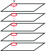
  is the entropy function. The variable defined by the intensities of a pixel x across all of the images is often referred to as an image stack, as illustrated by Fig. 3. The congealing method achieves groupwise image registration by iteratively deforming images one by one for minimizing the cost function defined by Eq. (2) until convergence. Its computational cost is very high since it requires one evaluation of the cost function defined by Eq. (2) for every update of the deformation parameters for each image.

(2)
 is a variable defined by the intensities of a pixel x across all of the images to be registered, and
  is the entropy function. The variable defined by the intensities of a pixel x across all of the images is often referred to as an image stack, as illustrated by Fig. 3. The congealing method achieves groupwise image registration by iteratively deforming images one by one for minimizing the cost function defined by Eq. (2) until convergence. Its computational cost is very high since it requires one evaluation of the cost function defined by Eq. (2) for every update of the deformation parameters for each image.
Fig. 3
Image stack used in the congealing method. The rectangles stand for input images and the red circles constitute a pixel stack at one pixel location 

To achieve efficient groupwise image registration, many groupwise image registration methods are built upon pairwise image registration. Basically, pairwise image registration is adopted to achieve groupwise image registration in two ways: (1) registering all images directly to a template image that can be a representative image selected from the images to be registered (typically a group center image) or iteratively to their evolving average image [2, 5, 6]; and (2) registering images to their similar images, known as intermediate templates, and then composing the resulting deformation fields to achieve the registration of all images to the representative image [3, 4, 7–9, 13, 14].
4 Groupwise Image Registration Using Direct Pairwise Image Registration
It is an intuitive way to achieving the groupwise image registration by directly registering all images to a template image [2, 5, 6]. The basic idea is to choose or to produce an image serving as a template from a given group of images. Then all the images in the given image group are registered to the template to achieve the final alignment (Fig. 4). The key of this kind of methods is how to determine an optimal template.
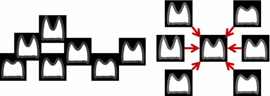

Fig. 4
Illustration of groupwise registration using direct pairwise image registration. Left input images; Right one input image is selected as a template and other images are registered to the template for achieving the final groupwise registration
The template image can be defined as the geometric mean of the input images based on their pairwise registration results [5]. In particular, each image is first registered to all the other images, then the geometric mean is estimated using the Multi-Dimensional Scaling (MDS) based on the registration result of all image pairs, and finally the closest image to the geometric mean is chosen as the template. In [75], the template image was defined as the average image of deformed input images, and each deformed input image was produced by warping the input image with the average deformation field resulted from averaging all deformation fields determined from pairwise image registrations between this image and all the other images. However, the template selection methods have relatively high computational cost since the pairwise image registration is required for every possible pair of images. As mentioned in [75], it would take 4096 h, i.e., 170 days, to get the template for an image group containing 64 images using one processor.
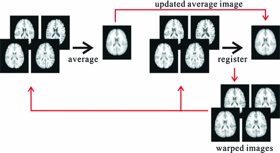

Fig. 5
Illustration of the iterative process of the groupwise registration method using the group average image as the template
Another efficient way to obtain the template is to generate the average image from the input images iteratively [6]. Particularly, an average image of registered input images using affine transformation is first generated as the template image and then all images are registered to the template image using a nonlinear registration method. The registered images can be averaged again to generate a new template image so that the groupwise image registration is improved iteratively. The iteration process stops when all images have been well aligned or the maximum number of iterations exceeded. The flowchart of such a groupwise image registration algorithm is shown in Fig. 5.
At the very beginning of the iterative groupwise image registration, images are typically not well aligned and the resulting average image is blurred. Such a blurred template image could hamper the groupwise image registration. To overcome this problem, a sharp average image can be generated using an adaptive weighting strategy at each iteration step [7]. The weight for each image’s pixel/voxel at each iteration step is inverse proportional to the squared intensity difference between image patches centered at the pixel/voxel in the image considered and the group mean image produced in the previous iteration step, so that the pixel/voxel in an image more similar (i.e., similar image intensity) to that in the group mean image contributes more to the pixel/voxel intensity in the new group mean image. The resulting group mean image is often with sharp contrast.
5 Groupwise Image Registration Using Intermediate Templates
Since the registration of similar images is typically easier than the registration of images that are much different from each other, several groupwise image registration algorithms have been proposed to register images to their similar images, referred to as intermediate templates, and then composing the resulting deformation fields for achieving the registration of all images to a representative image of input images [3, 4, 7–9, 13, 14]. The basic idea of this kind of registration methods for registering image A to final template R via intermediate template B is illustrated by Fig. 6. To determine the optimal intermediate template for each image, different strategies have been proposed [14, 71].
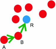

Fig. 6
Illustration of groupwise registration using intermediate templates. Red points indicate images. A is the image to be registered, B is the intermediate template, and R is the final template
A statistical deformation model has been used to generate the intermediate templates in a brain image registration method called RABBIT [14]. In particular, the method first gets a set of deformation fields that register a template brain image to individual brain images, and then applies Principal Component Analysis (PCA) to the deformation fields for generating a statistical deformation model that is able to characterize a brain image deformation field with a small number of parameters. To register the template brain image to a brain image, the statistical deformation model is used to generate a deformation field that warp the template image to produce an intermediate template close to the brain image considered, then a deformation field that registers the intermediate template and the brain image considered is estimated by a pairwise image registration algorithm, and finally the obtained deformation field is composed with that generated by the statistical deformation model to register the template brain image to the brain image considered. Since the difference between the intermediate template image and the image considered is relatively small, a better registration result can be obtained.
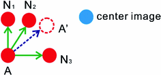

Fig. 7
Illustration of the registration strategy proposed in ABSORB. Given a group of image, represented by red points, to be registered, each image (e.g., A) is warped toward the group center with a deformation field obtained by averaging deformation fields warping A to its neighboring images ( and
and  ) that are closer to the group center than A itself. The procedure is iterated to warp all images to the group center image that is updated after each iteration step
 and
and  ) that are closer to the group center than A itself. The procedure is iterated to warp all images to the group center image that is updated after each iteration step
In most of groupwise image registration methods, the intermediate templates for each input image are its neighboring images chosen from the rest of input images. For example, in a method called ABSORB [71], each image’s neighboring images serve as its intermediate templates if the neighboring images are closer than itself to a group center image. The center image is determined by choosing the image near the group geodesic mean on an estimated manifold of input images using graph theoretic techniques (discussed in the Sect. 6). The groupwise image registration is then achieved by iteratively warping each input image with a mean deformation field obtained by averaging deformation fields that map the input image to its intermediate templates, as illustrated by Fig. 7.
Recently, graph theoretic techniques have been adopted in the groupwise image registration for learning a manifold of input images so that a large deformation between images can be decomposed into a series of small and anatomically meaningful deformations between similar images [3, 4, 8, 9]. The graph based groupwise image registration methods are intermediate template based registration methods too since some input images are used as intermediate templates of other images for achieving the final groupwise image registration. The representative groupwise image registration methods using graph theoretic techniques are introduced in Sect. 6.
6 Groupwise Image Registration Using Graphs
In the graph based methods, a graph of input images is constructed. In such a graph, each node corresponds to an input image and similar nodes are connected with edges. The weight of each edge connecting two images is determined by their similarity measure. The graph of images helps estimate the manifold of input images and the geodesic distance between two images can be approximated by the their shortest path in the graph identified using graphical algorithms, such as Dijkstra method [76]. Images on the shortest path between a pair of images can serve as intermediate templates and the registration between the pair of images can be achieved by subsequently composing deformations between all adjacent image pairs along their shortest path. Typically, a root image, which serves as the template, is first determined in the graph based methods, and then all images are registered to the root image along their corresponding shortest paths to the root. The template (or root) in the graph based methods is usually identified as a pseudo-geodesic mean of the images [8] by

where  is the length of the shortest path between images
  and
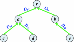
and  . Once the root image is determined and the shortest paths from non-root images to the root are fixed, a tree of images is obtained and the root of the tree is the group center of images. An example of such a tree with 6 images is illustrated in Fig. 8.

(3)
 is the length of the shortest path between images
  and
and  . Once the root image is determined and the shortest paths from non-root images to the root are fixed, a tree of images is obtained and the root of the tree is the group center of images. An example of such a tree with 6 images is illustrated in Fig. 8.
Fig. 8
Illustration of the graph based groupwise image registration. Each circle denotes one image, and  ,
,  , denotes a deformation field that registers image x to image y
 ,
,  , denotes a deformation field that registers image x to image y
 As shown in Fig. 8, there are 5 non-root images (denoted as  ) and each of them has a corresponding shortest path, following which the non-root image can be registered to the root image by subsequently composing pairwise deformation fields along the shortest path, i.e.,

where  is the shortest path from image x to the root image r, and
  denotes the deformation field mapping x to r. For instance, in Fig. 8 the shortest path of image c to the root image r is
  and the registration of image c to the root image can be achieved by subsequently composing deformation fields
  and
and  , i.e.,
  . The graph based registration methods help decompose a large deformation into small ones, and it is relatively easier to achieve accurate results for the registration of similar images than the registration of images with larger differences.
 ) and each of them has a corresponding shortest path, following which the non-root image can be registered to the root image by subsequently composing pairwise deformation fields along the shortest path, i.e.,
(4)
 is the shortest path from image x to the root image r, and
  denotes the deformation field mapping x to r. For instance, in Fig. 8 the shortest path of image c to the root image r is
  and the registration of image c to the root image can be achieved by subsequently composing deformation fields
  and
and  , i.e.,
  . The graph based registration methods help decompose a large deformation into small ones, and it is relatively easier to achieve accurate results for the registration of similar images than the registration of images with larger differences.
In the rest of this section, typical graph based methods are discussed in detail, and their performance in the registration of MR brain images is evaluated.
6.1 kNN Graph Based Groupwise Image Registration
Most of the graph based groupwise image registration methods adopt  graph to build the graph of images [4, 8]. In a
  graph, each node is connected to its k nearest neighboring nodes that are determined based on an image similarity measurement. The typically used image similarity is the Euclidean distance between image intensities defined as

where n is the total number of pixels/voxels in each image,  and
and  are the image intensities at location
  in images
  and
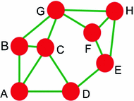
and  and respectively. An example kNN graph is shown in Fig. 9.
 graph to build the graph of images [4, 8]. In a
  graph, each node is connected to its k nearest neighboring nodes that are determined based on an image similarity measurement. The typically used image similarity is the Euclidean distance between image intensities defined as
(5)
 and
and  are the image intensities at location
  in images
  and
and  and respectively. An example kNN graph is shown in Fig. 9.
Fig. 9
An example of the graph construction using  algorithm. Each node is connected to its k nearest neighbors (
 ). For instance, node A is connected to B, C and D
 algorithm. Each node is connected to its k nearest neighbors (
 ). For instance, node A is connected to B, C and D
Fig. 10
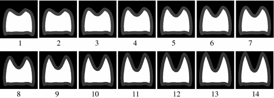
A set of synthetic images that have two peaks of different heights
The  graph has been demonstrated to be able to estimate the manifold of high-dimensional data such as images [77]. However, the performance of
  graph based method is sensitive to the selection of k. Therefore, the resulting shortest paths identified in a kNN graph, i.e., geodesic distances measured in the estimated manifold, are unstable. The sensitivity of
  graph based method is illustrated by the estimation of the manifold of synthetic images shown in Fig. 10. These images lie on a one dimensional manifold. The
  graph based estimation result varies very much with the parameter k, as indicated by the identified shortest paths of images to a group center image shown in Fig. 11. In particular,
  graphs with different settings of k are constructed based on similarity measures defined by Eq. (5), and then Dijkstra method is used to identify the shortest path from each image to the group center determined using Eq. (3). It is clear that the shortest paths for some images are changed dramatically with different settings of k. It is worth noting that the number in each circle shown in Fig. 11 corresponds to the image with the same number in Fig. 10.

 graph has been demonstrated to be able to estimate the manifold of high-dimensional data such as images [77]. However, the performance of
  graph based method is sensitive to the selection of k. Therefore, the resulting shortest paths identified in a kNN graph, i.e., geodesic distances measured in the estimated manifold, are unstable. The sensitivity of
  graph based method is illustrated by the estimation of the manifold of synthetic images shown in Fig. 10. These images lie on a one dimensional manifold. The
  graph based estimation result varies very much with the parameter k, as indicated by the identified shortest paths of images to a group center image shown in Fig. 11. In particular,
  graphs with different settings of k are constructed based on similarity measures defined by Eq. (5), and then Dijkstra method is used to identify the shortest path from each image to the group center determined using Eq. (3). It is clear that the shortest paths for some images are changed dramatically with different settings of k. It is worth noting that the number in each circle shown in Fig. 11 corresponds to the image with the same number in Fig. 10.
Fig. 11
The shortest paths derived from  graphs with different values of k. The root image is marked as a gray circle and the ID in each circle corresponds to the image with the same ID in Fig. 10
 graphs with different values of k. The root image is marked as a gray circle and the ID in each circle corresponds to the image with the same ID in Fig. 10
 The graph of images can also be constructed using a so-called  -ball method in a similar way to the
  graph method. Different from the
  graph method, the
  -ball method determines the neighboring images with connections to a given image in the graph using a distance threshold. In particular, given a group of images, each image’s neighboring images are those within a ball centered at the image considered with radius
  . Unfortunately, the
  -ball method has the same problem as the
  graph method.
 -ball method in a similar way to the
  graph method. Different from the
  graph method, the
  -ball method determines the neighboring images with connections to a given image in the graph using a distance threshold. In particular, given a group of images, each image’s neighboring images are those within a ball centered at the image considered with radius
  . Unfortunately, the
  -ball method has the same problem as the
  graph method.
6.2 kNN+MST Based Groupwise Image Registration
Built upon the  graph method, the Minimum Spanning Tree (MST) method has also been adopted to identify the shortest paths for images in groupwise image registration [4, 7]. The MST is a tree with minimal sum of edge weights. Two commonly used algorithms for constructing a MST are Prim’s algorithm [78] and Kruskal’s algorithm [79], and the latter can also be used to construct a minimum spanning forest if the graph is not connected, i.e., a MST for each connected component. The pseudo-code of Kruskal’s algorithm for connected graphs is summarized in Algorithm 9.1.
 graph method, the Minimum Spanning Tree (MST) method has also been adopted to identify the shortest paths for images in groupwise image registration [4, 7]. The MST is a tree with minimal sum of edge weights. Two commonly used algorithms for constructing a MST are Prim’s algorithm [78] and Kruskal’s algorithm [79], and the latter can also be used to construct a minimum spanning forest if the graph is not connected, i.e., a MST for each connected component. The pseudo-code of Kruskal’s algorithm for connected graphs is summarized in Algorithm 9.1.
Stay updated, free articles. Join our Telegram channel

Full access? Get Clinical Tree


