Fig. 8.1
a The J-shaped laparotomy is represented by the dashed yellow line: the midline starts at the root of the xiphoid process (which is always removed to open a better view over the anterior aspect of the hepatocaval confluence), and proceeds on the midline up to 3 cm above the umbilicus. At this point the transverse portion starts dividing the rectus muscle and approaching the costal arch at the level of the 9th intercostal space (ICS); b appearance of the J-shaped laparotomy after suturing; c the incision has to allow placement of the surgeon’s left-hand which sustains the liver aiding in controlling bleeding during dissection, and moreover, representing the backside landmark for guiding resection; d the hepatocaval confluence is perpendicularly visualized by means of removal of the xiphoid process: the yellow circle highlights the area; e this incision enables an adequate view of the retrohepatic area, allowing the liver to be retracted to the left but moreover pulled up from the inferior vena cava (IVC), rather than crushed against it as in the case of a subcostal access: dashed yellow arrows indicate the traction lines (upward and laterally to the left); right hepatic vein (RHV)
When the tumor is located in the paracaval portion of segment 1 or anywhere at the hepatocaval confluence, and the control of the hepatic veins at this level seems not fully achievable with the abdominal incision only due to patient characteristics and/or the tumor features (position, relations, and size), two solutions are possible. Both represent an extension of the J-shaped laparotomy and both aim to extend the working space for the surgeon especially at the mid-to-late phases of the dissection and in general when the major veins are approached. A J-shaped thoracophrenolaparotomy is shown in Fig. 8.2a, b: this incision allows the operator himself to have more space for positioning the left hand and for related liver handling (Fig. 8.2c, d), and moreover, allows a better view of the hepatocaval plane, which falls in line with the visual plane of the operator (Fig. 8.2e), being particularly useful for affording conservative resection of large tumors located in segment 1 (Fig. 8.3a–f). It is important to note that opening the chest may not be necessary for mobilization of the liver, but generally may be crucial during dissection and particularly towards the end when the specimen is detached from the hepatic veins and more space for handling particularly with the left hand could be needed. Therefore, paradoxically, chest opening is a maneuver more frequently carried out by expert surgeons rather than young fellows, since it is a decision derived from background experience that leads the operator to foresee the potential difficulties of the resection, and to shift to a thoracophrenolaparotomic approach without hesitation.
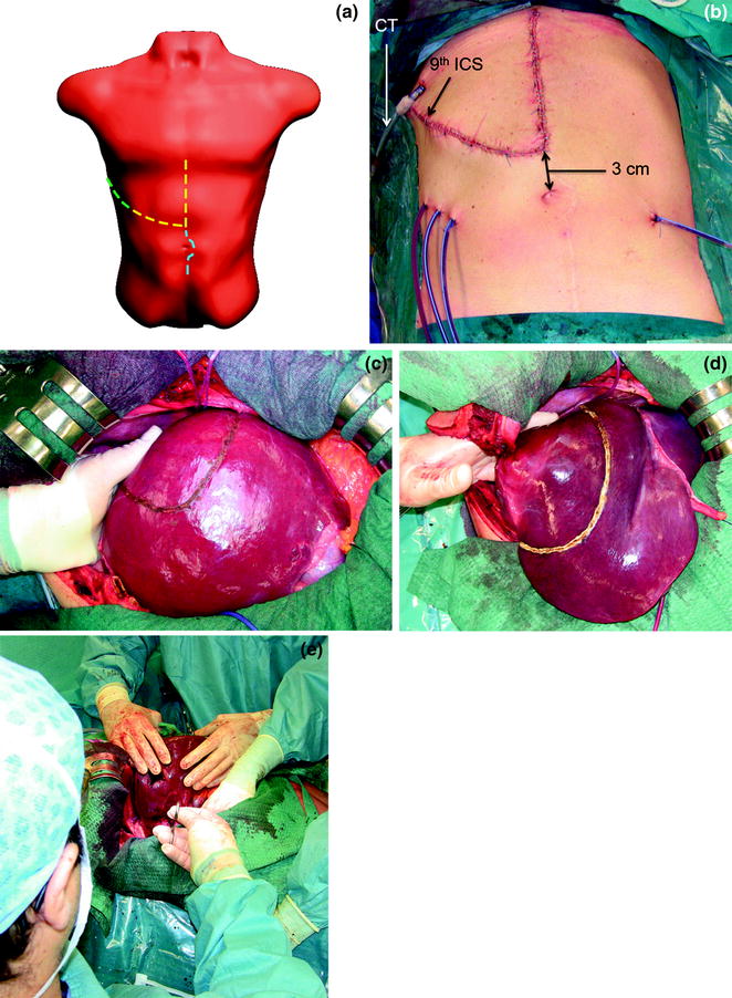
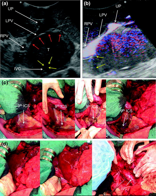
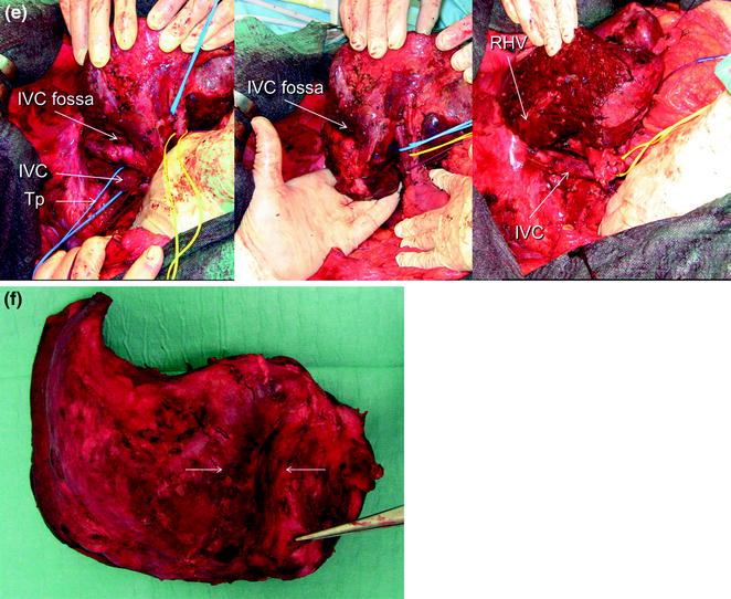
Fig. 8.2
a The J-shaped thoracophrenolaparotomy is represented by the dashed yellow line together with the green line. As for the previous incision, the midline starts at the root of the xiphoid process and proceeds on the midline up to 3 cm above the umbilicus. At this point the transverse portion starts dividing the rectus muscle and approaching the costal arch at the level of the 9th intercostal space (ICS) which is opened up to the posterior axillary line (the skin is divided up to the mid-axillary line); b appearance of the J-shaped thoraco-phreno-laparotomy after suturing; c, d this incision allows better placement of the surgeon’s left-hand compared to the abdominal approach only. This is particularly useful in case of lesions to be removed at the caval confluence especially if in a parenchyma-sparing modality: indeed, just after mobilization through an abdominal incision only, the surgeon may feel confident to handle the organ adequately. However, the difficulties raised by the lack of a thoraco-abdominal approach generally start in the late phases of the resections once the specimen has to be divided from the caval confluence and the left-hand handling would benefit from its placement through the opened intercostal space as shown in these pictures; e the surgeon’s perspective being seated while dissection of the liver from the inferior vena cava is performed; chest tube (CT)
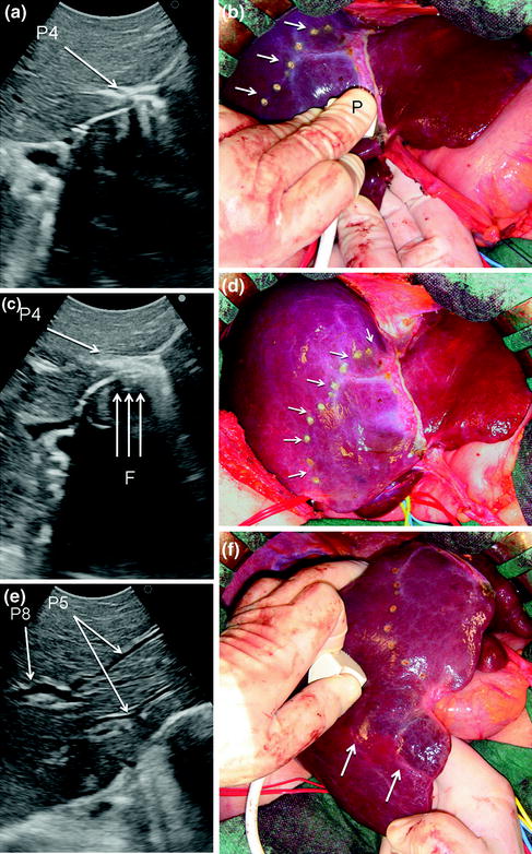
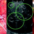
Fig. 8.3
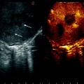
a IOUS of a large tumor (T) in segment 1 dislodging anteriorly and compressing (red arrows) the left portal vein (LPV) and surrounding and deforming (yellow arrows) the inferior vena cava (IVC); b CFIOUS image better showing the right-sided extension of the tumor (yellow arrows) to the caudate process; c from left to right, the progressive opening of the 9th intercostal space (ICS); d from left to right, the surgeon’s left hand positioned in the chest through the divided diaphragm (D) is pulling upward the liver; in this way the dissection of the retrohepatic plane is proceeded meticulously and progressively detaching the tumor from the inferior vena cava (IVC); e in this way dissection of the IVC from the tumoral fossa (IVC fossa) in which it was lying is completed without performing any resection of the vessel wall or proceeding to the total vascular exclusion although the tapes (Tp) were previously positioned for caution; f the specimen removed with the arrows indicating the IVC fossa; the right posterior section was also removed for the presence of two other lesions; right hepatic vein (RHV); right portal vein (RPV); umbilical portion (UP)
A median extension to the lower abdomen is selected (Fig. 8.4), particularly in case of an existing median incision: this access facilitates caudal tilting of the liver once mobilized (Fig. 8.5), and provides a larger space for positioning the left hand, then for handling the liver (Fig. 8.6). However, this access is not featured by a surgeon’s visual plane perpendicular to the hepatocaval space (Fig. 8.7), and is probably linked to a higher risk of wound hernias.
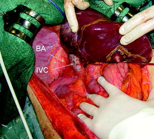
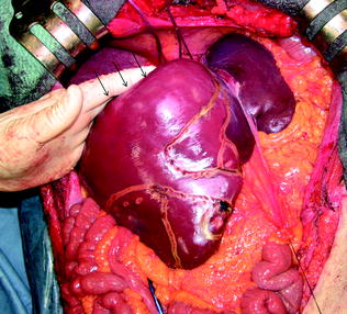
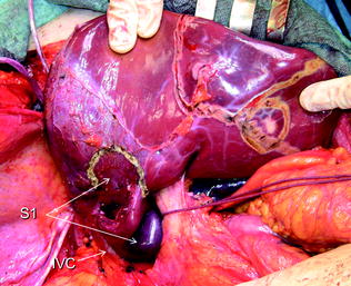
Fig. 8.4
The J-shaped laparotomy is extended distally on the midline (dashed blue line), particularly when associated procedures have to be performed in the mid-lower abdomen
Fig. 8.5
The midline extension allows adequate exposure of the bare area (BA) and the inferior vena cava (IVC)
Fig. 8.6
The midline extension also allows easier placement of the left hand with respect to the J-shaped incision if just laparotomic, and enables opening of the angle between the dome of the liver and the caval confluence of the hepatic veins by pulling the liver downward (arrows)
Fig. 8.7
The midline extension, although allowing easier placement of the left hand with respect to the J-shaped incision if just laparotomic, and permitting a complete hepatocaval dissection, as compared to the thoracophrenolaparotomic one, does not enable a perpendicular visual plane of the retrohepatic area; inferior vena cava (IVC); segment 1 (S1)
For right-sided segmentectomies or subsegmentectomies or sectionectomies the bare area is dissected and the right hemiliver is mobilized till the surgeon’s left hand is positioned behind the hemiliver, sustaining it, and as mentioned is comfortably positioned over the posterior aspect of the dissection plane drawn during the definition of the surgical strategy (Fig. 8.8). This mobilization should be extensive enough to allow allocation of the surgeon’s hand, and to avoid damaging of the adjacent structures, and particularly not to injure any short hepatic vein eventually left at the edge of the dissection area. Such an injury can be the source of conspicuous bleeding from the IVC, and can be massive as generally recognized late and potentially extended to the caval wall.
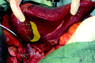
Fig. 8.8
The yellow area just at the edge of the dissection area drawn with the electrocautery (green arrows) shows the position of the left-hand’s fingertips during liver dissection to aid in driving the proper trajectory for liver division; diaphragm (D); inferior vena cava (IVC); lung (Lu)
Therefore, a slight mobilization of the right hemiliver just dividing the triangular ligament and partially or completely the bare area will be accomplished for lesions located in segments 5, 6, 7 inferior, and 8 ventral (Fig. 8.9a, b). Conversely, the right side of the retrohepatic IVC is reached for lesions located in segments 7 and 8 dorsal. If the lesion is located in segment 7 superior or 8 dorsal, close to the hepatocaval confluence (last 4 cm), but is not in contact with the hepatic veins, the hepatocaval ligament is not divided (Fig. 8.10a, b), and only the space between the RHV and the MHV is dissected for allowing fingertip insertion and eventual compression (Fig. 8.11a, b). The caval confluence of the RHV is recognized following the trajectory of the right inferior phrenic vein (RIPV), which flows into the IVC adjacent to the RHV, and for that a reliable landmark (Figs. 8.10b and 8.12) [1].
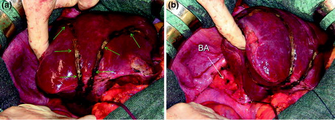
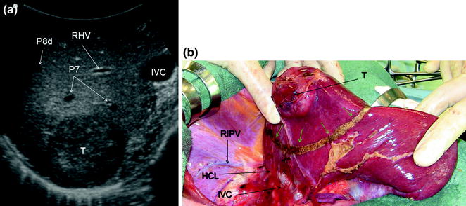
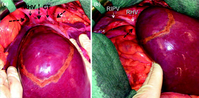
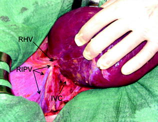
Fig. 8.9
For lesions located in the right inferior portion of the liver, for which limited resections (green arrows) could be enough (a), liver mobilization may be limited to the partial division of the bare area (BA) (b)
Fig. 8.10
For lesions (T) located close to the caval confluence, but without having close vascular relations (a), the dissection line (green arrows) is drawn relatively far from the caval confluence (b), and mobilization proceeds unless the inferior vena cava (IVC) is exposed but the hepatocaval ligament (HCL) may not be necessarily divided; right inferior phrenic vein (RIPV); right hepatic vein (RHV), portal branches to segment 7 (P7); portal branch to subsegment 8 dorsal (P8d)
Fig. 8.11
For lesions located close to the caval confluence, but without having close vascular relations, the hepatocaval confluence is prepared just for fingertip positioning enabling compression of the hepatic veins for reducing backflow bleeding: in (a) the dissection for finger positioning is shown, with the dashed black arrows indicating the place where the fingertip should be placed; in (b) a right-sided perspective indicating the posterior aspect of the right hepatic vein (RHV) is shown; common trunk (CT) of left and middle hepatic vein; right inferior phrenic vein (RIPV)
Fig. 8.12
The right inferior phrenic vein (RIPV) indicates the confluence of the right hepatic vein (RHV). This is particularly useful during dissections approaching the hepatocaval confluence in presence of adhesions between the diaphragm and the liver or in concurrence with tumoral invasion of the diaphragm itself
If the lesion is still right-sided but in contact with a hepatic vein at its caval confluence (Fig. 8.13a–g), or involves the paracaval portion of segment 1 (Fig. 8.14a–e), liver mobilization includes division of the hepatocaval ligament and exposure of the retrohepatic IVC till the area to be resected is under control of the surgeon’s left hand (surgeon’s fingertip getting over the most distal portion of the planned dissection plane) (Figs. 8.13b, and 8.14c). This detachment proceeds unless the control is obtained even though this means achieving complete detachment from the IVC (Fig. 8.15a–c). In this case, once the mobilization of segment 1 is complete and carried out through a right-sided approach, the left-hand fingertips are positioned at the edge between segments 2 and 1 where the Arantius’ ligament runs, somehow hooking the caudate lobe (Fig. 8.16).
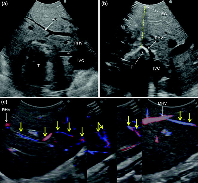
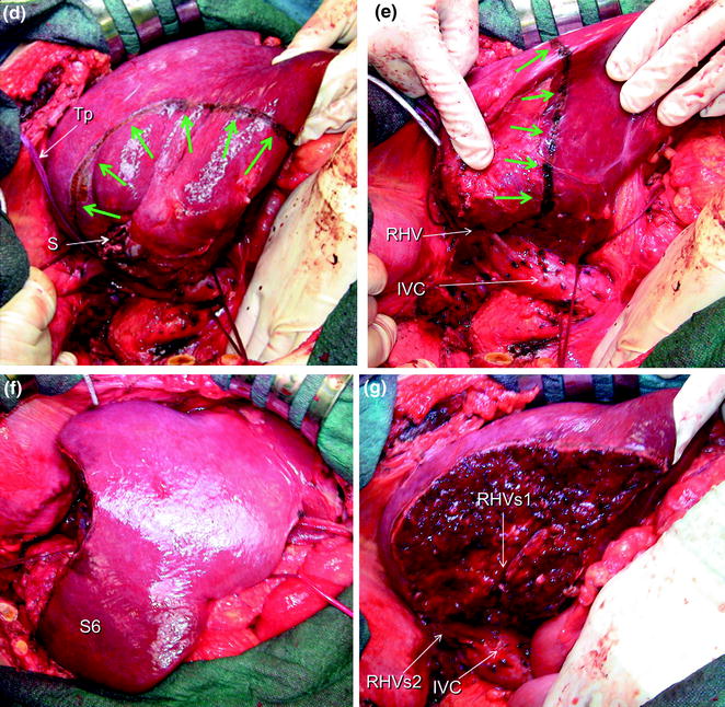
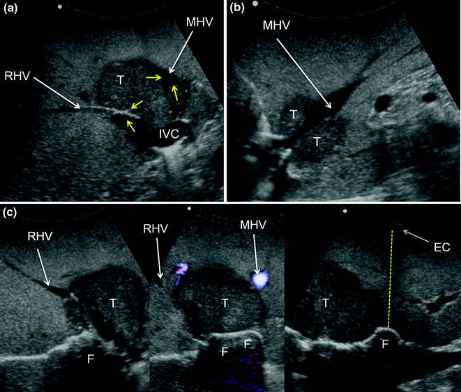
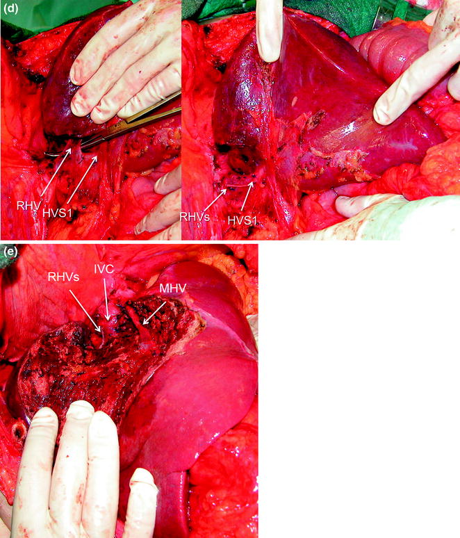
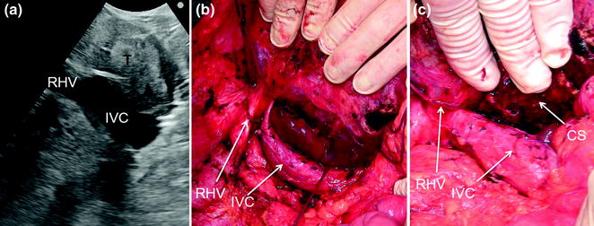
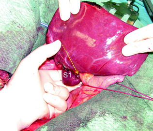
Fig. 8.13
a IOUS of a colorectal liver metastasis (T) previously treated and relapsed after thermal ablation and now invading the right hepatic vein (RHV) in proximity of its caval confluence; b upon adequate mobilization the surgeon’s fingertip (F) is placed between the tumor and the inferior vena cava (IVC) at the level of the RHV confluence, and together with the electrocautery (EC) being positioned on the opposite side, the virtual dissection plane is planned (dashed yellow line); c a communicating vein between the RHV and the middle hepatic vein (MHV) (yellow arrows); d, e the RHV is taped (Tp) and the resection area is drawn (green arrows); f, g the resection is carried out sparing segment 6 (S6) (f), which is drained by the communicating veins connecting the intrahepatic stump of the RHV (RHVs1) with the MHV (g); caval stump of the RHV (RHVs2); scar from previous thermal ablation (S); hepatic vein draining segment 8 and flowing into MHV (V8)
Fig. 8.14
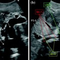
a IOUS of a colorectal liver metastasis (T) invading the right hepatic vein (RHV) and in wide contact with the middle hepatic vein (MHV) (yellow arrows); b a sagittal scan showing the MHV in another plan; c from left to right, these serial images show mobilization proceeding unless the fingertip (F) can be positioned on the left side on the tumor margin and together with the electrocautery (EC) on the opposite side of the liver the virtual dissection plane is drawn (dashed yellow line); d late phase of liver mobilization in which the RHV is taped and then resected preserving the vein draining the caudate lobe (HVS1); e resection is carried out sparing segments 5 and 6, and preserving MHV; inferior vena cava (IVC); stump of the RHV (RHVs)
Fig. 8.15
a IOUS of a tumor (T) occupying segment 1 (caudate lobe) and compressing and dislodging on the right the inferior vena cava (IVC); b the liver is then mobilized approaching it from both sides but preferentially on the right completely freeing the IVC; c resection is then carried out; cut surface (CS); right hepatic vein (RHV)
Fig. 8.16
Once the mobilization of segment 1 (S1) is completed by means of a right-sided approach, the left-hand fingertips are positioned at the edge between segments 2 and 1, where the Arantius’ ligament runs, somehow hooking the caudate lobe and the virtual dissection plane can be determined (dashed yellow arrow)
For segment 2 and 3 segmentectomies or subsegmentectomies, the left triangular ligament and the left coronary ligament are divided and with the surgeon’s left hand the left lobe is handled.
For lesions located at segment 4 superior at the hepatocaval junction, the mobilization combines the one described for lesions at segments 7 inferior and 8 ventral and for those in the left lobe. For these lesions once there is a relationship with the main trunk of the MHV, particular attention should be given to the fact that this vein is generally featured by a vertical confluence into the IVC (Fig. 8.17), which makes its length shorter than the others and its central position makes its compression more difficult. For these reasons, injury of this vein during dissection could be a source of massive bleeding and therefore preventive check of the control of the vein flow by finger compression (Fig. 8.18), or vein encirclement itself is always to be considered (Fig. 8.19).
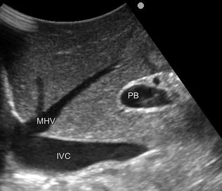
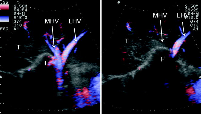
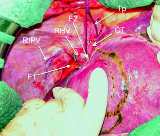
Fig. 8.17
IOUS shows the peculiarity of the middle hepatic vein (MHV) in most cases. It runs vertically toward its confluence into the inferior vena cava (IVC), and this has to be kept in mind during dissection in segments 4 and 5 seemingly far away from the hepatocaval confluence. Inversely, caval confluence is straight down a few centimeters, and consequently damaging the MHV may result in massive and usually unexpected bleeding, which may lead to panic unexperienced surgeons; portal bifurcation (PB)
Fig. 8.18
CFIOUS showing the aforementioned technique (see Chap. 7 and herein) for controlling backflow bleeding in those conditions in which the hepatic veins have not been encircled. Just before starting dissection, once the hepatocaval confluence has been prepared (as in Fig. 8.11) it is possible to verify under CFIOUS guidance the adequacy of finger compression (F) just checking the disappearance of the color-flow once the compression has been applied (from left to right); left hepatic vein (LHV); middle hepatic vein (MHV)
Fig. 8.19
Encirclement (Tp) of the common trunk (CT) and the sites for allocating the fingers for compressing the right hepatic vein (RHV) (F1) and the middle hepatic vein (MHV) (F2); right inferior phrenic vein (RIPV)
A particular trick that deserves to be mentioned is the use of IOUS to help mobilization when there are adhesions that may mask important structures to be recognized and preserved as the hepatic hilum, the IVC, and the hepatic veins. Just positioning the probe to localize these structures in relation to the dissection area and the distance between the latter and the structures themselves helps to avoid their damage and the severe consequences related to it (Fig. 8.20).
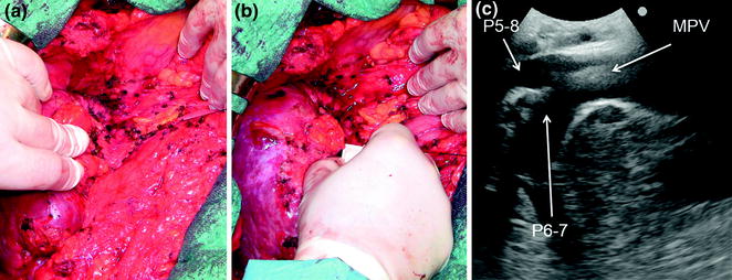
Fig. 8.20
a A surgical field with dense adhesions and an anatomy that, often due to previous operations and eventually previous resection too, has been modified; b the probe can be applied for better understanding the anatomy; c in this case it is useful to fix exactly the position of the hilar pedicle that has to be encircled avoiding its inadvertent damage; main portal vein (MPV); portal vein to the right anterior section (P5-8); portal vein to the right posterior section (P6-7)
8.2 IOUS-Guided Demarcation of the Resection Area
Demarcation of the resection area can be accomplished in an anatomical or nonanatomical fashion according to the type of the tumor, and the background liver. For anatomical demarcation the edges between adjacent portions of the liver having different inflow are outlined using various methods. However, before discussing these modalities, a brief comment on one of the most misleading uses of IOUS is required. The person with sufficient skills in IOUS within a surgical team usually is asked to disclose the plane containing the MHV by just contacting the probe with the liver surface. It is clear that any transverse or longitudinal scan merely viewing the MHV does not disclose the actual plane dividing the right and left liver in which the MHV itself is contained, since to define such a plane two landmarks are needed. Therefore, even for this purpose making apparent the demarcation line between the right and left liver on the hepatic surface is indispensable for identifying the only anatomical plane passing through the MHV (Fig. 8.21a, b).
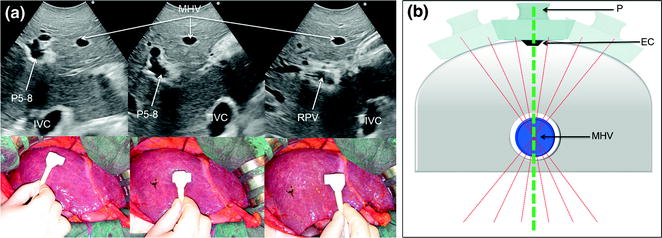
Fig. 8.21
a Comparison of different IOUS scans with related IOUS images, showing how it is misleading to consider the proper anatomical plan dividing the right and left liver anyone in which, by IOUS, the middle hepatic vein (MHV) is visualized. Here, three different scans are able to visualize the vein although other structures appear and disappear; b the elementary principle on which this finding is based: numerous plans (dashed red lines) pass through the single point represented by the MHV, but only one is adequate. To find the latter compulsorily requires another point as that represented by the demarcation line on the liver surface between the two hemilivers (Cantlie’s line), which can be marked with electrocautery (EC) and then allowing to disclose the proper line passing through the MHV (dashed green line); inferior vena cava (IVC); portal vein to the right anterior section (P5–8); probe (P); right portal vein (RPV)
8.2.1 Anatomical Resection
Selection of an anatomical resection for CLM seems not to be oncologically relevant [2], while its use for HCC is still controversial [3–8]: for the latter there are no studies comparing in a reliably randomized fashion anatomical and nonanatomical resections. However, reports show long-term benefits of the anatomical approach over the nonanatomical [3–6, 9, 10] both in a large series contest [5] and by a statistical analysis weighted to rule out the possible significant effect of selection biases that may afflict the reliability of the results [9]. The rationale for anatomic resection for HCC is based on its pattern of intrahepatic dissemination from the main lesion through the portal branches (Fig. 8.22). Thus, the resected specimen should include at least the portal area with the lesion (Fig. 8.23). On the other hand, the superiority of the anatomical resection seems more evident in those subgroups of patients with single HCCs larger than 2 cm in diameter [5] or with extranodular growth [10], which are usually those with higher risk of satellites and microvascular invasion.
Fig. 8.22
a Relation between an HCC (T) and its feeding portal vein (PV); b the HCC tends to disseminate within its segment, developing satellites (S); c later its attitude is to spread through the liver by disseminating through the portal tree, and invading it with tumor thrombi (TT)
Fig. 8.23
According to Fig. 8.22, the best local treatment for HCC (T) should be the removal, in addition to the nodule, also of the segmental or subsegmental area fed by the portal tree (PV)
However, no matter whether technical requirements for accomplishing truly anatomical sectionectomies and formal major hepatectomies are more uniformly accepted, the agreement on the requirements for defining a subsegmental resection as a real anatomical one is still vague, and thus a potential source of misunderstanding also in evaluating the data published in reports related to the topic. Indeed, recognition and demarcation of the segmental area to be removed in a fully anatomical way is still a matter of debate. The only certainty is that the segmental or subsegmental portal area feeding the tumor cannot be visualized on the liver surface without interventional techniques that allow their recognition. Almost all the proposed techniques are based on ultrasound guidance, especially in a cirrhotic liver where there are generally wide variations and abnormalities in the extension of the segmental areas. The first procedure described in this sense was the so-called systematic segmentectomy devised in the early 1980s [11]. The latter consists in the puncture of the portal branch feeding the tumor once the homolateral artery is clamped at the hepatic hilum: then the dye is injected into the punctured vein (Fig. 8.24a, b). More recently, alternatives to this approach have been devised.
Fig. 8.24
Performance of a systematic segmentectomy for an HCC (T), by identifying the portal vein (PV) feeding the lesion (a), and by injecting dye (generally indigo carmine) into PV once the homolateral hepatic artery is clamped at the hepatic hilum, allowing the selective coloring of the part to be removed (C), which corresponds to the segment or subsegment with the tumor (b)
The following paragraphs provide details concerning ultrasound-guided techniques for segmental and sectional resections.
8.2.1.1 Segmentectomies
Puncture of the Portal Branch
The portal branch feeding the tumor to be resected is punctured under IOUS-guidance through a free-hand technique or with a dedicated device, and then 3–5 ml of indigo carmine dye are injected into the vessel (Fig. 8.24a, b). The stained area becomes evident on the liver surface and is marked by electrocautery and the resection can be accomplished fully in an anatomical way. If the nodule is located between two adjacent segments, two portal branches afferent to the area should be punctured and injected. In this case, the deepest and most dorsal vessel must be punctured at first to avoid air bubbles contained in the dye from disturbing the ultrasonographic detection and puncture of the other branch. The portal branch is punctured 1–2 cm distally from its origin to avoid dye reflux and the direction and velocity of the infusion are controlled by IOUS. To prolong staining, the hepatic artery at the hilum is clamped before portal branch puncture. When there are numerous and thin vessels to be punctured or in the case of tumor thrombus in the segmental portal branch of the segment to be removed, the dye is injected in the portal branches afferent to the adjacent segments: this is the so-called counterstaining technique [12].
The above method remains the most precise way for segmental and subsegmental anatomical demarcation. Its main drawback, other than the required quite high skill of the surgeon in puncturing miniscule vessels, is the fact that if the ink regurgitates or is injected into the wrong portal branch, it could be then difficult to identify the proper area to be removed.
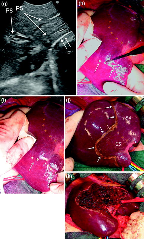
Compression of the Portal Branch
The procedure, as illustrated in Fig. 8.25a, b, initially was used for tumors located in the left hemiliver (see Fig. 1.10a in Chap. 1) [13], but more recently has been successfully extended to all segmental locations [14] and even to an entire sectional portion of the liver [15]. Once the feeding portal branch is identified by IOUS (Fig. 8.26a, e), it is compressed using the IOUS probe on one side of the liver and the finger on the opposite side (Fig. 8.26b, f), confirming the proper compression by IOUS real-time control (Fig. 8.26c, g). In this way it is possible to induce a transient ischemia of the portion of the liver distally to the compression site. This portion can be marked by electrocautery, the compression is released (Fig. 8.26d, h–j), and resection is carried out (Fig. 8.26k). This technique is simple, fast, noninvasive, and reversible. The possibility to modify the site of compression and then the resection volume allows tailoring the resection in function of the tumor features and the status of the background liver. Furthermore, the compression can be used in a countercompression perspective, alluding to the philosophy proposed by Takayama et al. of defining the adjacent segmental margins to disclose those of the targeted segment [12]. The latter was applied for complete and anatomical segment 1 resection using the aforementioned portal branches puncture technique. Indeed, for segments such as segment 8 and 4 superior for which direct compression of the feeding portal branch can be unfeasible, the compression of the adjacent segmental branch allows the definition of their segmental margins [14]. However, growing expertise has allowed to standardize the modality to perform a direct compression of segment 8 portal branch (P8) [16] (Fig. 8.27a–e), and even the selective compression of subsegmental branches feeding the ventral and dorsal portions of this segment (Fig. 8.28a–j), and that of the superior portion of segment 4 [17]. Briefly, the left hand of the surgeon together with the IOUS probe are positioned under IOUS guidance having P8 at the level selected for compression between them (Figs. 8.27a–e, 8.28a–j). A fundamental trick should be to select the compression site avoiding inadvertent compression of other vascular structures (Fig. 8.29a, b) that could mismatch the real segmental or subsegmental profile. Using the left fingertips and the IOUS probe itself, the surgeon compresses bilaterally the liver at the targeted position resulting in the compression of P8 (Fig. 8.27a–c) or its subsegmental ventral (P8v) (Fig. 8.28c–e) and dorsal (P8d) (Fig. 8.28f–h) branches; this maneuver is monitored constantly in real-time IOUS by means of the probe used for compression (Figs. 8.27a, 8.28c, e, f, h). For P8v, the probe compression sites are usually located on the superoanterior surface of the liver, and the finger compression sites are just in proximity and cranial with the hepatocaval junction (anterocranial approach). For the subsegmental dorsal area of segment 8, compression can be applied directly to its feeding portal branch (P8d) or on P7 as for a formal anatomical segmentectomy of segment 7 (Fig. 8.30a–e), but only in a countercompression manner. In both cases, the compression window on the IOUS scan is obtained by positioning the finger compression site on the posterior surface of the liver, which was previously mobilized (antero-posterior approach). Compression is maintained until the surface of the liver distal to the compression site starts to discolor (Figs. 8.26b, f, h, i, 8.27b, 8.28d, g, 8.30b). At this point, the assistant marks the discolored area by electrocautery and the compression is released (Figs. 8.26j, 8.27c, 8.28i, 8.30d).
Get Clinical Tree app for offline access
Fig. 8.25
Alternative approach for performing a systematic segmentectomy for an HCC (T) by identifying the portal vein (PV) feeding the lesion, and by compressing (red arrows) with the probe (P) and the finger (F) the feeding PV (a), determining a transient discoloring of the area (D), which can be marked with electrocautery (EC), and which corresponds to the segment or subsegment with the tumor (b)
Fig. 8.26
a IOUS scan identifying the common portal branch for segment 4 (P4); b once identified under IOUS guidance P4 compression is carried out by means of the probe (P) and the surgeon’s finger positioned on the opposite side, resulting in discoloring of the segmental portion to be removed (arrows); c the maneuver is monitored under continuous IOUS control; d the area is marked by electrocautery (arrows); e–i the same maneuver for the segment 5 portal branches (P5), which are identified in IOUS (e), then compressed revealing the discolored area (arrows) (f) under constant IOUS real-time control (g), and at the end the demarcation of the area (arrows) with electrocautery is performed (h, i); j
 Liver Transplantation from Living Donors
 Technical Tricks to Start Exploring the Liver with Ultrasound
 Diagnosis and Staging: Contrast-Enhanced Intraoperative Ultrasound (CEIOUS) Using Intravascular Contrast Agents
 Intraoperative Cholangio Ultrasound in the Study of the Biliary Tree
 Technological Requirements for Ultrasound-Guided Liver Surgery
 Exploring the Liver by Ultrasound Along its Anatomy


Related posts:
Liver Transplantation from Living Donors
Technical Tricks to Start Exploring the Liver with Ultrasound
Diagnosis and Staging: Contrast-Enhanced Intraoperative Ultrasound (CEIOUS) Using Intravascular Contrast Agents
Intraoperative Cholangio Ultrasound in the Study of the Biliary Tree
Technological Requirements for Ultrasound-Guided Liver Surgery
Exploring the Liver by Ultrasound Along its Anatomy
Stay updated, free articles. Join our Telegram channel
Full access? Get Clinical Tree
