
Robotic Microscopes
The ability to plan and perform complex neurosurgical procedures depends on the practical ability to navigate. Neuronavigation has progressed from a mental rendering of indirect anatomic reference points to a precise technology dependent on complex computational ability (i.e., computers). Like other types of navigation, neurosurgical navigation consists of two important elements. The first is the ability to plan a safe route from a starting point to a target destination. The second is the ability to determine current location in relation to the target and in relation to potential high-risk areas. In ocean navigation, the current location refers to the ship’s position. In most neuronavigational systems, the current location refers to the tip of a pointer. When a navigational microscope is used, the current position refers to the tip of a virtual pointer, the location of which is at the focal point of the microscope optical system.
The progression of computer science has allowed frame-based stereotaxy to evolve into frameless methods1,2 based on simple skin- or skull-based fiducial markers. Neural images, in the form of two-dimensional data such as computed tomographic (CT) scans, magnetic resonance imaging (MRI) scans, positron emission tomography (PET), or functional MRI (fMRI) can be obtained with a high degree of precision. These data can then be restructured into three-dimensional (3-D) views of the head and brain that can be registered for spatial orientation and manipulated by the surgeon. The surgeon can thus plan the starting point, target, and safest route prior to the actual surgery. This is equivalent to producing a navigational map for each procedure that can be individualized for the patient’s particular anatomy and pathology.
A robot is a mechanical device that follows instructions to accomplish a task usually done by a human. Robots are particularly appropriate when repetitive actions or extreme precision is needed. The advantage of a robotic microscope combined with frameless stereotaxy is that a number of functions normally dependent on the operator can be performed by computer-driven mechanisms. These actions, such as moving to the planned starting position, following a planned course, focusing accurately on the target point, and avoiding a preplanned risk area can all be done automatically with great precision. Further, the robotic control mechanisms allow specific movement patterns such as rotating the microscope around a predetermined focal point or rotating the viewing axis around a preselected point along the optical axis thus maximizing the amount of visible area through a small opening. This chapter describes the design and use of robotic microscopes with particular emphasis on the multicoordinate manipulator (MKM) robotic microscope and navigational system developed by the Carl Zeiss Corporation.
 Technical Features
The four principal components of a robotic stereotactic microscope system are the computer-based workstation, the robotic arm, the microscope itself, and the localizing system that allows monitoring of head or instrument location (Fig. 11–1).
At the heart of the system is the computer and workstation. It is the high-speed computer that allows manipulation of the 3-D image data in relation to the microscope virtual pointer. Additionally, merging or fusion of different types of images can be done to take advantage of the differing kinds of information available through different imaging modalities (i.e., CT, MRI, fMRI, PET). The workstation allows image manipulation and thus determination of complex volumetric shapes and precise spatial definition of anatomy and pathology. Using this image-based information, anatomically safe approaches can be developed. The computational power of the MKM system is provided by a DEC Alpha workstation, running STP software (Leibinger, Freiburg, Germany), on a UNIX-based platform or a PC Windows-based system. These systems are equipped with digital audiotape (DAT) drives and optical drives thus allowing image data entry when direct line connection is unavailable.
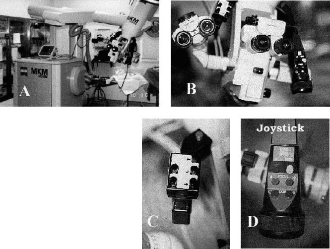
FIGURE 11–1. Some of the components of a robotic system. (A). The base of the microscope and the robotic arm used to position the microscope at the desired site. (B). The microscope, which is not unusual except for the two arms that are illustrated in C and D. (C). The left-hand grip of the robotic scope. This allows the user to leaf through many of the user menus, displayed in the heads-up display in the right ocular, without removing attention from the microscope. (D). The joystick, which allows operator movement of the microscope using the motors built into the robotic arm. Additionally, this handle contains a button that instructs the microscope to autofocus at the point of the crosshairs and buttons that allow operator-controlled focus and operator-controlled zoom (MKM Zeuss, Thornwood, NY).
The second component is the robotic mechanism. This is a positioning arm with six degrees of freedom (i.e., base rotation; translation in three primary axes: x, y, z; and two other rotational axes). The positioning mechanisms are motor driven and can be controlled either by an operator-maneuvered joystick or by computer-generated instructions. The operator-generated movements can be devolved into only orthogonal x, y, and z movements or only rotational movements centered on the focal point of the microscope system using permissive-selection buttons located on the joystick. The position of the arm is continually relayed back to the computer. The MKM microscope, base, and arm are motorized and internally encoded with an inherent accuracy of up to 0.75 mm. The robotic nature of the microscope also allows the scope to pivot around a point of focus, orient itself at any time along a planned trajectory, pivot around a cylinder (keyhole) to allow examination of a larger area when the surgical corridor is narrow, or go to any predetermined position under computer control.
The third component is the microscope itself, which is mounted on the robotic arm. The most important aspect of the microscope mechanism is the ability to accurately focus in response to operator-generated commands. This mechanism, based on laser matching, allows extremely precise and accurate focus. Currently, the Surgiscope by Leica (Allendale, NJ)3 and the MKM by Zeiss (Thornwood, NY)4 both use laser beams to provide the location of the focal point to their robotic microscopes. The MKM uses a Class I laser as its autofocus system with an accuracy of within 0.3 mm of its critical focus and with the 0.75 mm accuracy of the robotic arm gives an overall accuracy of 1.05 mm. The dynamic focus has a working range of 200 to 400 mm. This focal point location is relayed to the computer, which in turn computes the location of the area under focus and displays it on the monitor in the form of crosshairs on the three orthogonal planes of the image (CT or MRI) forming the navigational basis of the case as well as a 3-D rendering of the head. An added benefit is the ability to display the planned surgical approach, distance to target points, and outlines of predetermined important pathological or risk structures at the current plane of focus in one of the eyepieces as a heads-up display (HUD). This allows clear orientation for the surgeon without the need to continually look up from the point of surgical concentration. The microscope has a zoom ratio of 1:6. It is mounted with a stereo beam splitter to provide stereoscopic vision and 12.5× eyepieces. The microscope also has an attached microphone for verbal commands that can be programmed for up to 15 surgeons and allows manipulation of the microscope without removing either hand from the operative field. The microscope uses a xenon light source for constant temperature regardless of intensity. In addition to the microscope’s manual controls, there are foot controls allowing another means of altering focus, zoom, and movement. All that is then required for the system to be functional is a constant, or at least measurable, spatial relation between the target and the robotic arm base. This is accomplished by fixing the position of the microscope base and registering the spatial location of the head using fiducial markers.
The fourth component is a localization system that will allow the locations of various tools to be determined and will also allow changes in head position to be determined. Several different types of systems are currently available to locate the fiducial markers and pointing devices. There are magnetic systems,5,6 which develop a magnetic field around the head and, based upon its interference or modulation, reconstruct the 3-D localization data. However, they are subject to position degradation by nearby ferromagnetic materials such as most surgical instruments. Ultrasonic detectors7 have been used in a similar capacity with emitters based around the microscope objective along with receivers that calculate the speed and modification of returned sound waves to reconstruct the area under observation and obtain localizing data. This methodology is also fraught with complicating factors such as interference with reflectors or other objects in the operative field. In addition, the temperature of the room and its relative humidity may influence sound velocity and, thereby, the computational accuracy of this system. The sound transmitters and receivers can be influenced by the draping methods around the microscope. Mechanical arms can also be used as pointer devices.1,2,8,9 They rely on mechanical determination of position of the arm based on their articulated joint positions. Several systems are now available that rely on the optics of operating microscopes and their proximity to the intraoperative region of interest to generate localizing data that can be interpreted by the computing system and provide the surgeon with knowledge of his or her current position.10–14 As in the microscope system we describe, localizing technologies are frequently combined and used to advantage.
Optical digitizers use information from light that can be emitted and then captured using infrared or laser cameras.10,12–15 This avoids optical interference from ambient sources such as operating room lights. Infrared systems10,12,15,16 utilize light-emitting diodes (LEDs), which emit pulsed infrared signals and are attached to the patient’s head through the head clamp. This allows continuous monitoring of the head’s position in space. Similar systems have been used with nonrobotic microscopes such as BrainLAB’s VectorVision system.10,12,16 The initial head position in relation to the microscope is determined by registering the fiducial markers placed on the scalp or implanted in the skull. The registration can be done using either the microscope focal point as the virtual pointer or a real pointer located with attached LEDs. Once registration is completed, the relative position of the microscope to the head in space and hence all the points in the images are known. Like other navigational systems, it is this spatial relation that allows accurate use of the stereotactic information.
 Neuronavigation Procedure
Skin fiducials are placed on the patient’s scalp on the afternoon or evening before surgery. Bone-based fiducials are also available and have the apparent advantage of slightly higher accuracy. Positioning the fiducials is important. There should be at least six and preferably eight fiducials placed. They should be as widely separated on the head as possible, remembering that if the microscope is to be used to register the fiducials, they must be in a visable position (i.e., the person placing the fiducials must be aware of the head position to be used during surgery). Fiducials should not be placed in the low suboccipital area because the patient will be lying on this part of the head during scanning and thus may distort the positions of the fiducials. At this point appropriate images are obtained. If fMRI routines are to be performed, they must be accomplished prior to contrast administration.
 Imaging Protocols
Related posts:

Stay updated, free articles. Join our Telegram channel

Full access? Get Clinical Tree


