(1)
Department of MRI, Medical Center at Siegerland Airport, Burbach, Germany
For the installation of low-field MR systems, particularly with permanent magnets, certain special requirements have to be considered. The specific advantages of these systems influence the concept of the scan site and enable to realize MR imaging units in locations that are impossible to service with high-field systems. However, there are certain prerequisites that must be taken into account.
3.1 MRI System Components
A typical magnetic resonance system consists of a number of components. The components, their weight, and power consumption values for a Siemens Magnetom C! with a field strength of 0.35 T are given in Table 3.1.
Table 3.1
System dimensions Siemens Magnetom C!, 0.35 T. Source: Siemens Healthcare planning Dept., Erlangen/Germany
Component | Weight [kg] | Power consumption [W] |
|---|---|---|
Magnet | 16,308 | 2000 |
Patient table | 200 | |
RF cabin | ||
RF door | ||
RF window | ||
RF filter plate | 80 | 150 |
EFI pickup coil | ||
Electronics cabinet | 600 | 2000 |
Heat exchanger (gradient) | 310 | 9400 |
Power supply | 35 | |
User console | 20 | 200 |
Host PC | 22 | 700 |
Intercom | ||
Switch on box | 1 | |
Air conditioned |
3.2 Room Size and Conditions
Spatial requirements for most low-field systems are limited. A minimum room size of 30 m2 (325 sq. ft) would be sufficient (www.siemens.com/medical) (Fig. 3.1).
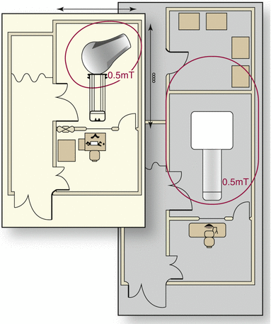

Fig. 3.1
Space requirements of a typical low-field MR setting (20–30 m2) compared to a high-field system (40–60 m2) (Courtesy: Esaote Inc.)
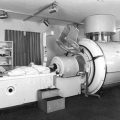
This enables installation in small buildings or, if a larger room is available, improves access to the patient, emphasizing the openness of the MR, which is important for claustrophobic or handicapped patients. The creation of an attractive and aesthetic design for the scan room (Fig. 3.2) is eased by permanent magnet systems.
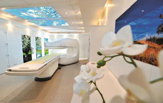

Fig. 3.2
Patient-oriented scan room design for open low-field MRI (Photography: Ulrich von Born)
Open design improves access to the patient for interventional or surgical MR-guided procedures (Petersilge et al. 1997; Yamada et al. 2015). Access to the patient is easier; positioning of instruments and medical equipment is facilitated. Additionally, anesthesiologists appreciate the reduced missile effects of ferromagnetic instruments (see below).
Since the need for air ventilation and cooling is limited, the room height can be reduced. The size of gradient amplifiers is smaller, and there are no cryogenic components (Helium compressor). Therefore, the technical components can be installed in a smaller cabinet, giving additional flexibility. Minimum height is typically only > 225 cm.
The examination room temperature is required to be between 21 and 27 °C, at a humidity of 40–80 %.
The technical room temperature is required to be between 18 and 24 °C, at a relative humidity of 40–80 %.
The operator room temperature has to be between 15 and 30 °C at a relative humidity of 40–80 %.
Heat production of the MR components is about 2 KW in the examination room, about 2 KW in the operator area, and maximally 11.4 KW in the tech room.
The scan room needs an antistatic floor.
To enable remote control and maintenance, a high-speed connection has to be provided. Ideally, an Ethernet connection with a data transfer rate of more than 100 MBit/s should be available.
3.3 Transport and Installation
For unloading of the system, particularly the magnet, sufficient space for truck and cranes has to be provided. The door openings have to be of adequate size. The magnet weight of 16 tons requires strong and stable transport ways (Fig. 3.3).
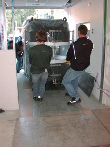

Fig. 3.3


Installation of a 0.35 T magnet (Siemens Magnetom C!, Siemens Healthcare, Germany). Important: protection of the floor by steel plates
Stay updated, free articles. Join our Telegram channel

Full access? Get Clinical Tree


