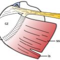
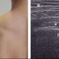
Figure 3-1. Rotator interval: proximal level. [A] Positioning of the probe for short-axis view of the LHBBT (see figure 1-11A for arm positioning). [B] Corresponding 12-5 MHz US image demonstrates the LHBBT (t), the coracohumeral ligament (arrowhead), the humerus (hum), and the capsular interface (asterisks).
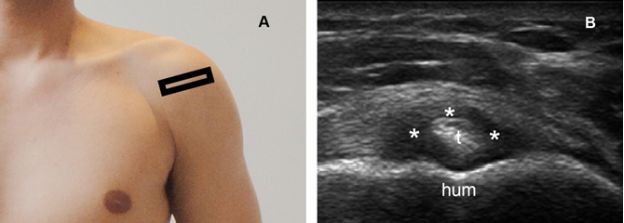
Figure 3-2. Rotator interval: distal level. [A] Positioning of the probe for short-axis view of the LHBBT (see figure 1-11A for arm positioning). [B] Corresponding 12-5 MHz US image demonstrates the LHBBT (t), the humerus (hum), and the biceps reflection pulley (asterisks). The medial cord of the coracohumeral ligament and the superior glenohumeral ligament form the biceps reflection pulley. The roof of the pulley is composed of the coracohumeral ligament, while the superior glenohumeral ligament comprises the deep fibers of the pulley that elevates the medial aspect of the undersurface of the LHBBT and causes the tendon to assume an oblique orientation relative to the bone cortex.

Figure 3-3. Intertubercular groove: proximal level. [A] Patient positioning. [B] Positioning of the probe. [C] Corresponding 12-5 MHz US image demonstrates the LHBBT (t), the lesser tuberosity (Lt), and the greater tuberosity (Gt).
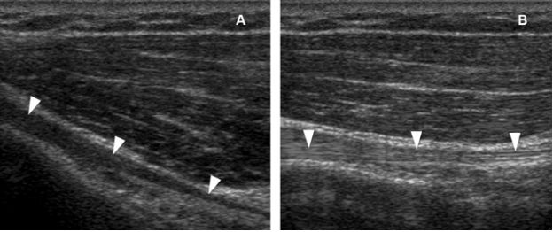
Figure 3-4. Sagittal anisotropy. [A] Long-axis 12-5 MHz US image shows anisotropy of the LHBBT (arrowheads) because the insonating beam is not perpendicular to the tendon fibers. [B] A small tilt on the inferior aspect of the probe corrects anisotropy and depicts normal hyperechoic fibrillar pattern of the tendon (arrowheads).

Figure 3-5. Axial anisotropy. [A] Short-axis 12-5 MHz US image shows anisotropy of the LHBBT (arrowhead). [C] Slight angulation of the probe greatly reduces anisotropy and depicts normal hyperechoic tendon (arrowhead). Lt= lesser tuberosity. Gt= greater tuberosity.
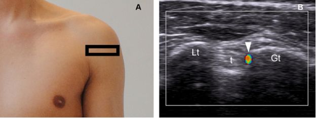
Figure 3-6. Ascending branch of the anterior circumflex artery. [A] Positioning of the probe. [B] Corresponding axial 12-5 MHz color Doppler image shows normal ascending branch of the anterior circumflex artery (arrowhead) adjacent to the LHBBT (t). Lt= lesser tuberosity. Gt= greater tuberosity.
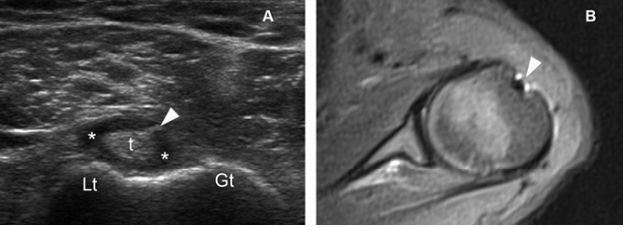
Figure 3-7. Mesotendon. [A] Axial 12-5 MHz US image shows the LHBBT (t). A small amount of synovial fluid (asterisks) makes the mesotendon more conspicuous (arrowhead). [B] Corresponding axial STIR MRI also shows the mesotendon (arrowhead). Lt= lesser tuberosity. Gt= greater tuberosity.

Figure 3-8. Intertubercular groove: distal level. [A] Patient positioning. [B] Positioning of the probe. [C] Corresponding 12-5 MHz US image demonstrates the LHBBT (t) and the pectoralis major tendon (arrowheads).
Stay updated, free articles. Join our Telegram channel

Full access? Get Clinical Tree


