
Sources of Error in Image Registration for Cranial Image-Guided Neurosurgery
Registration is the process of computing a mapping between coordinates in one space and those in another, such that points in the two spaces that correspond to the same anatomical point are mapped to each other. Registration of multimodal images makes it possible to combine different types of structural information [e.g., x-ray computed tomography (CT) and magnetic resonance (MR) images] and functional information [e.g., positron emission tomography (PET) and single photon emission tomography (SPECT) images] for diagnosis and surgical planning. Registration of images acquired with the same modality at different times allows quantitative comparison of serial data for longitudinal monitoring of disease progression/regression and postoperative follow-up. Registration of preoperative images with the physical space occupied by the patient during surgery is a fundamental step in interactive, image-guided surgery (IGS) techniques. Surgical navigation systems use the image-to-physical registration (IPR) transformation to track in real time the changing position of a surgical probe on a display of the preoperative images. Stereotactic procedures use the transformation to direct a needle (stereotactic biopsy) or energy (stereotactic radiosurgery) to a surgical target (e.g., tumor) visible in the images.
Many methods have been used to register medical images. Image-guided stereotactic surgical procedures have been performed since the early 1970s using stereotactic frame systems. Such systems generally include a reference frame that provides rigid skull fixation using pins or screws and establishes a stereotactic coordinate system in physical space, a method for stereotactic image acquisition, and a system for mechanical direction of a probe or other surgical instrument to a defined intracranial point. Most current systems relate image space to the physical coordinate space established by the reference frame by attaching a localizing system consisting of N-shaped fiducials during image acquisition. Frames permit neurosurgeons to perform biopsies and to resect deep-seated and previously inaccessible lesions. Frame-based techniques, however, have several limitations. The frames are bulky and may interfere with the surgical exposure. Patients complain about the weight of the frame and the pain associated with its application. The surgeon is typically limited to target points on a linear trajectory. And, perhaps most importantly, frame-based stereotactic systems do not provide real-time feedback to the surgeon about anatomical structures encountered in the surgical field. To address these limitations, a number of frameless IGS systems have been developed over the last decade.
For most types of monomodality and multimodality image-to-image registration (IIR), research has demonstrated that the most effective and accurate algorithms are those based on intensities. Point-based and surface-based methods can also be used for these applications, but they require a greater degree of user interaction and typically exhibit lower accuracy than intensity-based methods. Techniques based on points and surfaces do, however, play an important role in IPR, which is important in IGS and radiosurgery because the internal information necessary for intensity-based registration is typically unavailable in physical space intraoperatively.
In this chapter, we make a few general comments about image registration, note how it is related to image fusion, and present several applications of IIR and IPR transformations. Then we discuss three sources of error in image registration—geometrical distortion in preoperative images, error inherent in the registration process, and intraoperative brain deformation. We limit our discussion to frameless image registration (i.e., point-based, surface-based, and intensity-based registration).
 Registration, Fusion, and Surgical Navigation
As already described, registration is the determination of a one-to-one mapping or transformation between the coordinates in one space and those in another, such that points in the two spaces that correspond to the same anatomical point are mapped to each other. This concept is illustrated in Figure 2–1. The left picture shows the patient’s head during surgery; the middle and right pictures show CT and MR image slices of the patient’s head, respectively. The arrows represent the one-to-one mapping between the same anatomical point—in this case a point on the cortical surface in the left hemisphere—in physical space, CT, and MR. The simplest mappings are rigid-body transformations, which are transformations in which the distances between all pairs of points are preserved. A rigid-body transformation can be decomposed into a rotation and a translation. Most methods used to register head images compute a rigidbody transformation, which assumes that the head is approximately a rigid body, or a rigid-body plus anisotropic scaling transformation, which is used to correct for scaling error (image voxel dimension error).
To make the registration beneficial in terms of medical diagnosis or treatment, the transformation or mapping that the registration produces must be applied in a clinically meaningful way by a system that will typically include registration as a subsystem. For IIR, the larger system, which might be an IGS system, may combine the two registered images by producing a reformatted version of one image that can be combined or fused with the other. Image reformatting is the mapping of image intensities onto points in a space that has been rotated and/or translated relative to the space in which the image was originally acquired. A common example is the creation of sagittal and coronal image slices from an image volume that was acquired with transverse slices. Another example is the reformatting of an image after it has been registered to some target image such that each voxel in the reformatted image represents the same anatomical location as the corresponding voxel in the target image. Fusion of one image with another image to which it has been registered and reformatted may be accomplished, for example, by simply summing intensity values in the two images voxel by voxel, by superimposing outlines from one image on the other image, or by encoding one image in hue and the other in brightness in a color image. Regardless of the method employed, image fusion should be distinguished from image registration, which is a necessary first step before fusion can be performed successfully. Nonetheless, several manufacturers of IGS systems refer to image registration as image fusion. Alternatively, the larger system may use the registration simply to provide a pair of movable cursors on two views linked via the registering transformation so that the cursors are displayed at corresponding points.
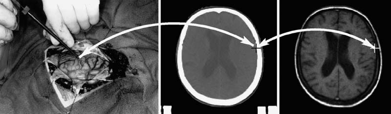
FIGURE 2–1. Concept of registration. Registration is the determination of a one-to-one mapping or transformation between the coordinates in one space and those in another, such that points in the two spaces that correspond to the same anatomical point are mapped to each other. The left picture shows the physical space occupied by the patient’s head during surgery. The middle and right pictures show CT and MR image slices of the head, respectively. The arrows represent the one-to-one mapping between the same anatomical point—in this case a point on the cortical surface in the left hemisphere—in physical space, CT, and MR.
Image registration and fusion is useful for combining complementary structural information (e.g., soft tissue from MR with bone from CT). This is illustrated in Figure 2–2. Image fusion is also very useful for interpreting functional imaging and incorporating it into an IGS system for navigation.1 When functional images such as PET, SPECT, functional MR (fMRI), and MR spectroscopy (MRS) are coupled with high-resolution anatomical images through image registration and fusion, the functional, metabolic, and biochemical properties can be linked to the anatomic structures in which they occur. Surgical navigation with an IGS system can then be employed to resect lesions on the basis not only of their structural abnormalities but also of their functional characteristics. Applications for structural–functional image fusion include the ability to differentiate between recurrent tumor and radiation necrosis, accurately identify a tumor’s boundaries (particularly those surrounded by edema), and determine a particular pathology’s relationship to eloquent cortex. The ability to identify eloquent cortex accurately is extremely beneficial, as these areas are often shifted greatly in the presence of a mass lesion. Registration of images acquired with the same modality at different times allows quantitative comparison of serial data for longitudinal monitoring of disease progression/regression and postoperative follow-up.
Surgical navigation systems use the IPR transformation to track in real time the changing position of a surgical probe on a display of the preoperative images, to direct a needle (biopsy) or energy (radiosurgery) to a surgical target located in the images, or to augment reality by superimposing information derived from the images (e.g., tumor contour) on the surgical scene viewed through a microscope2 or head-mounted display.3 Planning for a surgical procedure can be performed preoperatively with an IGS system. Intraoperatively, the surgeon can travel along the predetermined pathway to the desired target. Surgical navigation facilitates the use of smaller craniotomies for the complete resection of lesions. The location and size of the craniotomy can be determined exactly, and structures such as the frontal sinus, mastoid air cells, venous sinuses, and large draining veins can be avoided or at least anticipated. Once the bone flap is removed and the dura is opened, the IGS system can direct the surgeon to the area of the tumor, which may not be apparent from the overlying cortical surface. During cortical dissection to a tumor, vital vascular anatomy that is not necessarily grossly obvious can be identified and preserved. During gross total resection of a tumor, surgical navigation can demonstrate depth in relation to an instrument’s position (i.e., anatomy deep to the area of dissection) so that vital vascular and neural structures can be avoided; display the actual extent of the tumor on the basis of its contrast enhancement or metabolic activity in three dimensions, which may not be appreciated when the tumor is infiltrating and grossly resembles normal brain parenchyma; and provide a frame of reference to help with intraoperative orientation during dissection. During resection of an arteriovenous malformation (AVM), surgical navigation using an MR angiography (MRA) image can help identify arterial feeding vessels.
Figure 2–3 illustrates two surgical navigation applications of the IPR transformation. The top row shows a sample screen from an IGS system in which the IPR transformation is used to display in real time the changing position and orientation of a tracked endoscope on triplanar reformatted preoperative CT image slices (bottom three panels), the endoscope video image (top right panel), and a synthetic (virtual) perspective rendering generated from the same viewpoint as the endoscope using the CT image (top left panel). By changing opacity values when generating the rendering, the physically visible surface can be made transparent and structures below the surface can be visualized. In this case, the synthetic rendering shows the optic nerve (arrows). The bottom row shows two images obtained at different orientations from an augmented reality (AR) system.3 In the AR system, virtual objects, in this case a texture-mapped dot pattern representing the surface of a tumor segmented from an MR image and a cylinder representing an interactively manipulated biopsy needle, are overlaid on video images of the real-world scene viewed by the surgeon. Depth perception is provided by stereo disparity (each of these images is only one of a stereo pair seen by the surgeon in a head-mounted display), motion parallax, and perspective.
The application of a transformation produced by image registration for image fusion and surgical navigation is clinically useful only if coordinates in the two images or in the image and physical space that correspond to the same anatomical point are accurately mapped to each other. Registration error is the error of this mapping (registration error is defined more carefully in the section Error Inherent in the Registration Process). In Figure 2–3, the IPR transformation is used to correctly place internal anatomical objects onto the video images of the real-world scene. If there is error in the IPR transformation, the anatomical objects will appear in the wrong location. The rest of this chapter is concerned with three important sources of error in image registration: (1) geometrical distortion in preoperative images, (2) error inherent in the registration process, and (3) intraoperative brain deformation. There will always be some error. It is important for the surgeon to know the possible sources of registration error to minimize this error, to know the magnitude of registration errors typically obtained with different registration methods, and to better understand how IGS systems work and what some of their limitations are.
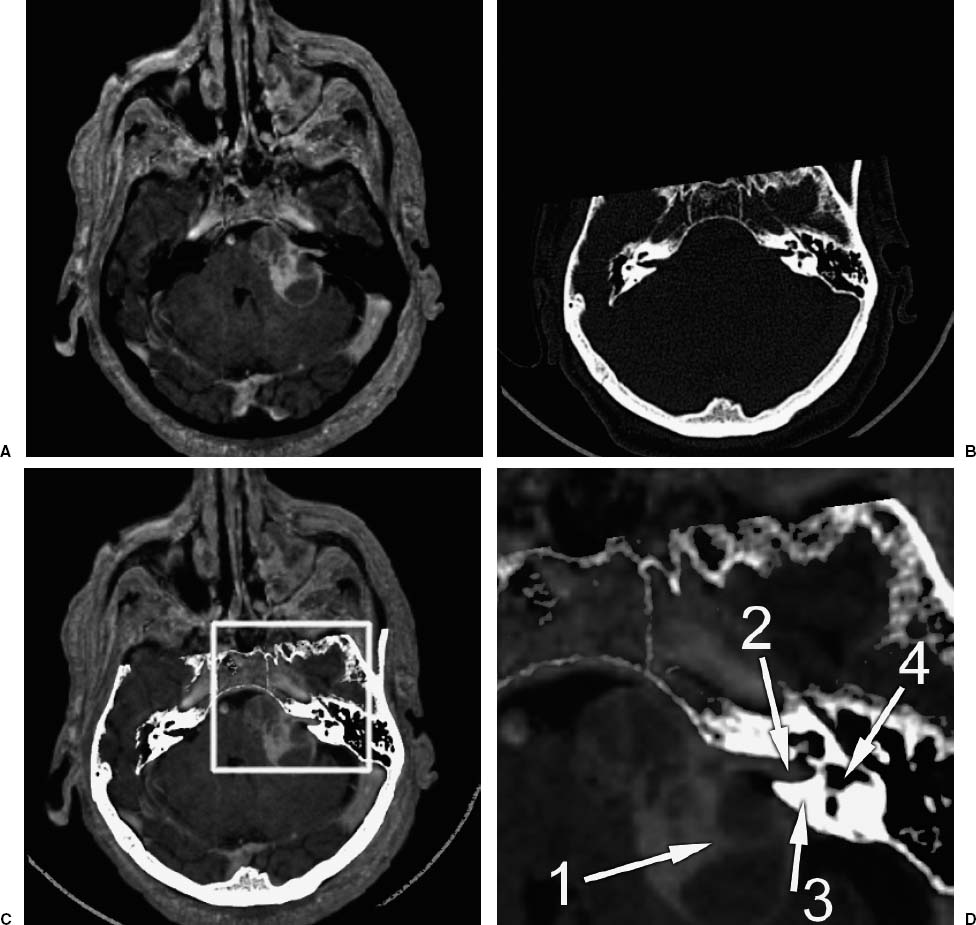
FIGURE 2–2. Example of image fusion. This is an application of the transformation determined by image-to-image registration (IIR). (A). A slice from an MR image (T1-weighted gradient-echo sequence) of a patient with an acoustic neuroma. (B). A slice from a CT image from the same patient that has been registered (i.e., the transformation from CT to MR has been determined), and reformatted (i.e., a new slice has been interpolated from the original image such that each voxel in the reformatted CT slice represents the same anatomical location as the corresponding voxel in the MR slice). (C). A fusion of the MR and CT images. The bone was segmented from the reformatted CT image by thresholding and combined with (added to) the MR image. (D). A magnified image of the region inside the box highlighted in (C). Arrow 1 points to the tumor. Arrow 2 points to the acoustic nerve and tumor running through the auditory canal in the petrous bone. Arrow 3 points to the petrous bone. Arrow 4 points to one of the semicircular canals in the bone. The fused image is useful because it combines complementary image information—soft tissue from MR with bone from CT. (Adapted from Rohlfing T. Multimodale Datenfusion fur die bildgesteurte Neurochirugie und Strahlentherapie [Ph.D. thesis]. Berlin: Technical University Berlin; 2000.)
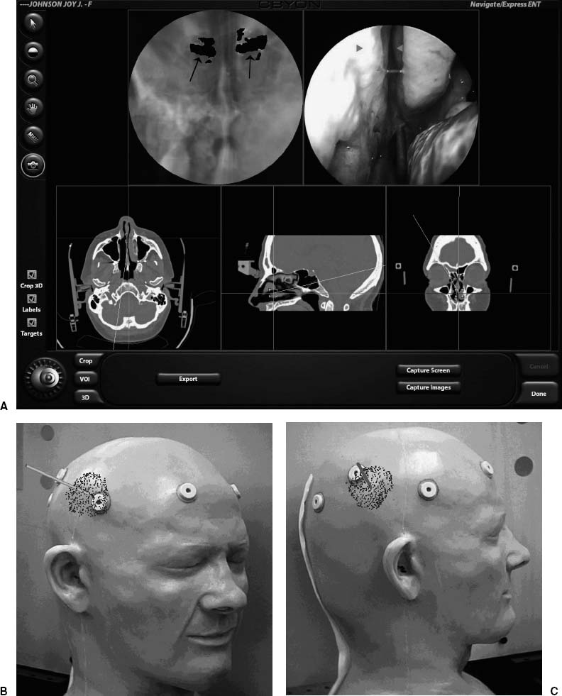
FIGURE 2–3. Applications of the transformation determined by image-to-physical registration (IPR). (A). A sample screen from a surgical navigation system in which the IPR transformation is used to display in real time the changing position and orientation of a tracked endoscope on triplanar reformatted preoperative CT image slices (bottom three panels), the endoscope video image (top right panel), and a synthetic (virtual) perspective rendering generated from the same viewpoint as the endoscope using the CT image (top left panel). By changing opacity values when generating the rendering, the physically visible surface can be made transparent and structures below the surface can be visualized. In this case, the synthetic rendering shows the optic nerve (arrows). (B,C). Two images obtained at different orientations from an augmented reality (AR) system.3 In this AR system, virtual objects, in this case a texture-mapped dot pattern representing the surface of a tumor segmented from an MR image and a cylinder representing an interactively manipulated biopsy needle, are overlaid on video images of the real-world scene viewed by the surgeon. Depth perception is provided by stereo disparity (each of these images is only one of a stereo pair seen by the surgeon in a head-mounted display), motion parallax, and perspective. The IPR transformation is used to correctly place internal anatomical objects on the video images of the real-world scene.
 Geometrical Distortion in Preoperative Images
The medical images we are interested in are three-dimensional (3-D) arrays of elements called voxels. Each voxel has an intensity value associated with it that represents the average value of some quantity. In CT, for example, the intensity represents the average x-ray attenuation coefficient over the region covered by the voxel. Spatial sampling (discretization) of the underlying continuous image constitutes a loss of information by partial volume averaging; structural information on the scale of the voxel dimension and smaller is lost. Point-based registration error is proportional to fiducial marker localization error, which decreases as the ratio of the fiducial marker size to voxel dimension increases. The effective total system accuracy, sometimes referred to as application accuracy, cannot be better than the voxel gresolution.a Thus it is helpful to acquire images for IGS that have small voxel dimensions. Fortunately, current CT and MR scanners can easily produce images with voxel dimensions on the order of 1 mm or better in each direction.
a It is possible with an image processing algorithm to determine the centroid of a fiducial marker in an image with subvoxel accuracy (e.g., Wang et al4). Such an algorithm can exploit knowledge about the marker (e.g., its shape and size). But it is generally not possible to manually identify a surgical target with accuracy better than the voxel dimension.
Geometrical distortion in CT images
There are two common types of intensity artifacts in CT images. The first is streak artifacts, which are caused by the presence of electron-dense materials with such high x-ray absorption that the attenuation is outside of the dynamic range of the scanner. Thick bone such as the skull base, dental fillings, and the pins of some stereotactic frame systems often cause such artifacts. The other is beam hardening artifacts, which are a consequence of the fact that the x-ray beam is composed of a spectrum of photon energies. As the polychromatic x-ray beam transits through the patient and is increasingly attenuated, the lower energies are preferentially removed, causing an increase in the effective or average energy of the beam, thereby decreasing the calculated attenuation coefficient. These artifacts do not affect the geometrical fidelity of the image, but they can interfere with fiducial marker localization or surgical target identification.
The spatial fidelity of CT image slices is determined largely by the number, position, and operating characteristics of detecting sensors, and is, therefore, relatively constant between studies and independent of the specific patient imaged. Slice thickness is determined from bThe N-shaped fiducial localization systems typically used in stereotactic frame systems are immune to image voxel dimension error and tilt angle error. The development and success of point-based and surface-based frameless IGS systems is due in large part to substantial improvement in the geometrical fidelity of images produced by current scanners. the table positions corresponding to the image slices. Table position is accurately measured and recorded in current CT scanners. In our experience at several major university hospitals, quality assurance testing of CT scanners is very good and geometrical distortion in routinely acquired clinical CT image slices is very low. Nonetheless, we have on rare occasions observed problems with linear scale distortion (image voxel dimension error) or tilt angle error.b
b The N-shaped fiducial localization systems typically used in stereotactic frame systems are immune to image voxel dimension error and tilt angle error. The development and success of point-based and surface-based frameless IGS systems is due in large part to substantial improvement in the geometrical fidelity of images produced by current scanners.
A CT image volume is a stack of two-dimensional (2-D) image slices. If a CT image is acquired with the gantry tilted, and the image slices are simply stacked without accounting for the nonzero tilt angle, then the image volume will have a type of geometrical distortion called shear. If the tilt angle is known, it is straightforward to generate an image volume that is free of shear distortion. Most, if not all, current CT scanners produce image file formats that contain the gantry tilt angle in the image header. Unfortunately, many current IGS systems cannot account for a nonzero tilt angle in their software, and for such systems it is important to acquire a CT image without gantry tilt.
Because CT image volumes are stacks of sequentially acquired slices, any patient movement between slices distorts the image. In addition to the normal difficulties of keeping a person still, head movement can be caused by inertial jerking during each table advance in conventional CT image acquisition. Helical CT image acquisition involves continuous patient translation during x-ray source rotation and produces a complete image volume in a relatively short period of time. Some current CT scanners feature multiple detector arrays; multislice helical CT image acquisition is extremely fast. These scanner improvements reduce the risk of significant head movement during scanning and thus are quite useful for cranial IGS scan acquisition.
Geometrical distortion in magnetic resonance images
A detailed description of MR imaging is beyond the scope of this chapter; however, some fundamental understanding of spatial encoding is required to understand the source of geometrical distortion in MR images. Many excellent books and review articles exist for the interested reader (e.g., Haacke et al5).
The resonance of hydrogen protons placed in a magnetic field produces radio waves. The frequency of the radio wave signal is proportional to the strength of the local magnetic field. The amplitude of the signal is proportional to the density of hydrogen protons. A large sample placed in a static and spatially homogeneous magnetic field produces a signal with only a single frequency. Images are created by encoding the spatial positions of the precessing hydrogen protons. This is accomplished by applying linear, orthogonal gradients on a static magnetic field. Because the resonant frequency is proportional to the strength of the local magnetic field, impressing a linear gradient on a static magnetic field will result in a proportional gradient of resonant frequencies.
Three different spatial encoding methods are used. The most important in terms of geometrical distortion is frequency encoding. A linear magnetic field gradient is applied while the MR signal is received. This gradient is commonly referred to as both the frequency-encoding gradient and the readout gradient. The spatial positions of precessing hydrogen protons are encoded by the frequencies of their emissions; the change in frequency is proportional to distance. The amplitudes (densities) and positions of the hydrogen protons in the object are decoded from the received signal using a Fourier transform.5 Inhomogeneity in the static magnetic field causes an error in the frequency at that position and thus results in a spatial error in the frequency-encoding gradient direction. The magnitude of the geometrical distortion is proportional to the error in the static magnetic field: Δx = ΔB0/Gx, where Δx is the spatial error in the frequency-encoding direction, ΔB0 is the error in the static magnetic field, and Gx is the strength of the frequency-encoding gradient.
Phase encoding is another spatial encoding method. In this case, a linear magnetic field gradient is applied, but instead of being applied while the MR signal is received, it is applied momentarily just before the signal is received. MR signals are complex quantities (i.e., they possess both magnitude and phase). The briefly pulsed gradient alters the phase of the signal; the change in phase is proportional to distance. The densities and positions of the hydrogen protons in the object are determined by applying multiple pulses of gradually increasing amplitude and receiving a signal for each pulse.5 Theoretically, there is no geometrical distortion due to static field inhomogeneity in the phase-encoding gradient direction. This is because the position of a hydrogen proton source depends on the difference in phase between pulsed phase-encoding gradients, which in turn depends on the difference in the strength of the magnetic field at that location. This change in the strength of the field is due only to the step increase in amplitude of the phase-encoding gradient and is independent of the strength of the static magnetic field at that location.
Spatial position in the third direction is achieved in two different ways. In the first way, a slice of interest is defined by applying a radio frequency (RF) excitation pulse while a slice-selection gradient is applied in the slice direction. The slice-selection linear magnetic field gradient defines a gradient in frequency that corresponds to a gradient in slice position. An RF pulse is applied with a range of frequencies that corresponds to the spatial range (position and thickness) of the image slice to be excited. An alternative method is to excite a thick slab (the size of the image volume) and encode position in the slice direction using phase encoding. In the first case, static field inhomogeneity causes a spatial error in the slice-selection gradient direction, and the magnitude of the geometrical distortion is: Δz = ΔB0/Gz, where Gz is the strength of the slice-selection gradient. However, the strength of the slice-selection gradient is typically much higher than the strength of the frequency-encoding gradient, and geometrical distortion in the slice-selection gradient direction is generally less than 1 mm, unless there are very large static field inhomogeneities. Slice position phase encoding has the same absence of geometrical distortion due to static field inhomogeneity that in-plane phase encoding has.
Accurate spatial localization requires a static and spatially homogeneous magnetic field and linear, orthogonal gradients. Spatial inhomogeneity in the static field causes geometrical distortion in the frequency-encoding gradient direction. Current clinical MR scanners are designed and manufactured such that they have a very uniform static magnetic field when no object is present in the scanner. Static magnetic field inhomogeneities and gradient nonlinearities can be corrected, or at least minimized, by using shims and electronic compensation circuits.6 The presence of an object in the scanner can cause static field inhomogeneity in several ways. Metal causes severe local warping of the static field, especially if the metal is ferromagnetic or has a ferrous component, as is the case with some types of stainless steel. Common sources of metal artifact in MR images of the head include dental fillings and appliances, implants (e.g., aneurysm clips), and shrapnel.7 An area of zero or low signal is generally prominent near the metal, and is often surrounded by a region with visually obvious spatial distortion. The intensity distortion gradually returns to normal, and far from the metal the image may appear spatially accurate. Nonetheless, there can be subtle yet clinically significant geometrical distortion in areas of the image that appear normal. A stereotactic targeting error of approximately 20 mm has been reported in a patient with dental braces.8 Severe geometrical distortion caused by a needle accidentally left in the scalp has been observed.9 Spatial distortion due to static magnetic field inhomogeneity caused by a metal hairpin located in the magnet has been noted.10
Objects consisting of media with different magnetic susceptibilities induce perturbations in the static magnetic field. The object-induced static field inhomogeneity causes geometrical distortion in the frequency-encoding gradient direction.11–12 Air and tissue have different magnetic susceptibilities, and the object-induced effect is strongest in regions near air—tissue interfaces. This includes the scalp and areas near air-filled cavities (e.g., the frontal sinus, ethmoidal air cells, sphenoid sinus, mastoid air cells, and nasopharynx). Object-induced static field inhomogeneity at the scalp surface can distort the image position of skin-affixed and bone-implantedc fiducial markers and the skin surface, and thus increase the error of point-based and surface-based registration methods that use this information. Figure 2–4 shows an example where the basilar artery is misregistered by approximately 3 mm because of geometrical distortion in the MR image. The cause of the registration error is probably object-induced geometrical distortion of both the fiducial points used to register the images and the position of the basilar artery. Since the magnitude of the distortion is inversely proportional to the frequency-encoding gradient strength, increasing the strength of the gradient will reduce the spatial error. The frequency-encoding gradient magnitude for this example was 1.5 mT/m. Many current MR image pulse sequences use a substantially higher gradient strength than that used for the image in Figure 2–4. Gradient-echo MR images are often acquired with frequency-encoding gradient magnitudes of approximately 5 mT/m; the object-induced geometrical distortion for such images would be approximately one-third of the distortion observed for the image in this figure. Spatial distortion due to magnetic susceptibility differences can also occur in the region surrounding a cavernous hemangioma because of hemosiderin deposits.15
c A bone-implanted marker typically has a base or post that is screwed into the outer table of the skull of the patient (see Fig. 2–5). An image marker, which is attached to the base during image acquisition, is located at or near the air–skin interface.
Hydrogen protons in fat have slightly lower MR frequencies than protons in water molecules because of the influence of neighboring carbon atoms. Such differences in resonance frequencies are the basis for MRS, but in standard clinical MR images these differences cause spatial error in the frequency-encoding gradient direction that is analogous to the error caused by static field inhomogeneity. The spatial error of fat relative to water is often referred to as chemical shift. Because the distribution of fat is relatively homogeneous throughout the brain, chemical shift is generally not important in MR images of the brain (the chemical shift of subcutaneous fat is visually obvious, but is rarely, if ever, important for cranial neurosurgery). However, it is important not to use fiducial markers containing fat (e.g., vitamin E capsules) because the position of such markers will be shifted relative to the brain. When chemical shift is important, selective saturation or selective excitation MR imaging methods can be used to produce water-only (fat-suppressed) or fat-only images.
To minimize the problem of spatial distortion in the frequency-encoding direction due to static magnetic field inhomogeneity and chemical shift, there are several simple guidelines to follow when acquiring MR images for IGS:
1. Use the highest frequency-encoding (readout) gradient strength possible. Since the magnitude of geometrical distortion due to static field inhomogeneity is inversely proportional to the frequency-encoding gradient strength, increasing the strength of the gradient will reduce the spatial error. Using the smallest field of view and highest matrix dimension possible will help maximize the gradient strength. There is a trade-off between gradient strength and signal-to-noise ratio (SNR) (i.e., increasing the strength of the gradient will increase the image noise). Though the SNR in an MR image is generally a more important factor than spatial fidelity in diagnostic imaging, the opposite is true for therapeutic imaging, and it is sometimes acceptable to sacrifice some SNR to improve spatial fidelity.
2. Consider using a volume gradient-echo pulse sequence. Theoretically, no geometrical distortion due to static field inhomogeneity is expected in the phase-encoding gradient direction. Such sequences apply phase encoding in two directions.
3. Use a global shim before each patient is scanned. Global shimming will reduce static field inhomogeneity and thus geometrical distortion. Current MR scanners provide automatic global shim procedures that are fast and reliable.
4. Avoid using fiducial markers containing fat or oil.
Several methods for correcting geometrical distortion in the frequency-encoding gradient direction due to static field inhomogeneity are available. One general approach involves creating a map of the static field inhomogeneity. This can be accomplished by acquiring two gradient-echo images with slightly different echo times (TE) and calculating the phase difference between the two images.16 The inhomogeneity map is used to compute the spatial error at each voxel and thereby undistort the image. This approach, which has been implemented at several institutions,17–19 requires an additional image and special software that is not commercially available and thus is not widely used. A different approach requires two spin-echo images that are acquired with the identical imaging parameters, except that the frequency-encoding gradient is reversed.14 A practical alternative to these correction methods is to acquire an MR image such as SPAMM (spatial modulation of magnetization).20 This imaging method uses special pulse sequences to superimpose a grid on the image. Static field inhomogeneity distorts the grid lines, which, without distortion, are parallel and perpendicular to each other. Although this type of image can be used for correcting geometrical distortion, it can also be used to quickly visually assess whether substantial static field inhomogeneity and the associated spatial distortion is present in the therapeutic image.
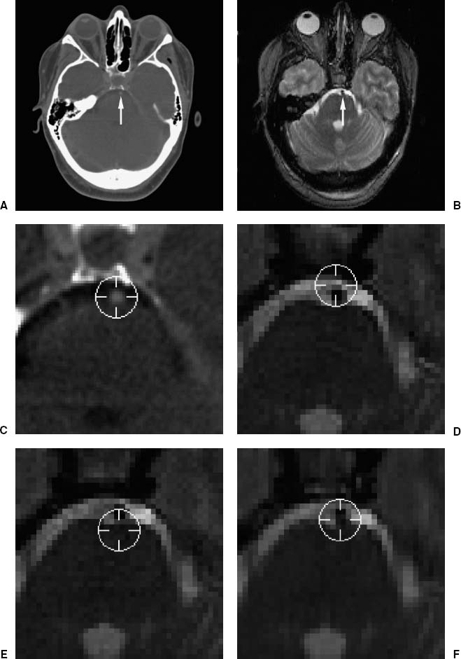
FIGURE 2–4. Example of the effect of geometrical distortion in MR on registration error. (A). Transverse CT and (B) MR image slices. The images were registered using five bone-implanted markers.13 The arrows point at the basilar artery. (C–F). Enlargements of the region about the artery, which lies ventral to the pons. The position of the artery was manually identified in CT, where the artery appears slightly brighter than its surroundings. Periscope cursors were drawn at the user-identified position in CT (C) and at the corresponding positions (computed using the IIR transformation) in MR (D–F), where the artery appears darker than its surroundings. (D,E). A distorted pair of normally acquired MR images that were acquired with identical imaging parameters except that the frequency-encoding gradient (oriented in the anterior–posterior direction) was reversed. (F). A rectified image generated from (D) and (E) using the method in Chang and Fitzpatrick.14 The cursor center is clearly anterior (D) or posterior (E) to the artery in the original (unrectified) images. It appears to be closer to the artery in the corrected image (F). The magnitude of TRE at the basilar artery due to geometrical distortion in the original (unrectified) MR images is approximately 3 mm. Geometrical distortion is substantial in this T2-weighted spin-echo MR image primarily because the frequency-encoding gradient magnitude is relatively low (1.5 mT/m). (Modified from Maurer CR Jr, Aboutanos GB, Dawant BM, et al. Effect of geometrical distortion correction in MR on image registration accuracy. J Comput Assist Tomogr 1996;20:666–679. With permission.)
Another type of geometrical distortion is scaling error (i.e., error in the image voxel dimensions), which results from error in the magnitudes of the linear gradients used for spatial encoding (miscalibration). This type of error is not uncommon and is extremely important when it occurs. The voxel dimensions of diagnostic images do not need to be known very accurately, and this may be why clinical MR scanners are sometimes poorly calibrated. In our experience with a variety of MR scanners at several institutions, scaling errors of 1 to 2% are not uncommon, and errors of 2 to 3% are not rare.d A scaling error leads to errors in the distances between points in the image. For example, if there is a 2% scaling error in an image with a 200 mm field of view, there is very little error in the distance between adjacent points, but an error of 4 mm between points at either side of the image. Scaling error is generally anisotropic (i.e., the scaling errors in the three dimensions are different from each other).
d Several examples of clinically relevant scaling error have been reported: 1.0% in-plane and 1.9% axial mean error, with a maximum error in one patient of 3.7%,21 a range of 0.4 to 1.7% in-plane and 1.3 to 3.0% axial error,22 a maximum error of approximately 1%.23 For eight patients who underwent stereotactic radiosurgery at the University of Rochester, scaling error determined using a nine DOF MR-to-CT image registration ranged from 0.6 to 1.9% in-plane and 0.9 to 2.4% axial error (unpublished data).
There are two major approaches for correcting scaling error in MR images. One obvious idea is to image a phantom (test object) of known shape and size.22–24
Related posts:
 Intraoperative Image Update by Interface with Ultrasound
Stay updated, free articles. Join our Telegram channel

Full access? Get Clinical Tree


