3.2 Sampling of Tissue Blocks (Location)
The aim of the sampling procedure is to allow every part of the lungs an equal chance of being represented in the analysis. Thus, in each step when the fraction of the reference volume that is being analyzed is reduced, an appropriate sampling technique needs to be applied. An efficient and reliable way to do this is referred to as systematic uniform random sampling, which is described in detail below (23). It should be noted, however, that there are several other sampling methods, e.g., fractionator, smooth fractionator (24, 25), stratified sampling, which may prove to be particularly useful for a specific scientific question (see Note 15). Here, we assume that the sampling procedure serves to provide an unbiased sample for three different purposes: methacrylate-, paraffin-, and epoxy resin-embedded samples.
1.
If the reference volume has been measured by fluid displacement, process the lungs according to Subheading 3.1.2, steps 3 and 4 of the Cavalieri method.
2.
Arrange the slices in their natural order (beginning with the first and ending with the last or vice versa) in a row and number them.
3.
Three systematic uniform random sets of slices are determined by a random start between 1 and 3 and a constant sampling interval of 3. Assign one of the numbers between 1 and 3 randomly to each of the embedding procedures.
Example: A total of 11 slices was sectioned. The random number assigned to glycol methacrylate is 2, to paraffin is 1, and to epon is 3. Then slices 2, 5, 8, and 11 are sampled for methacrylate, slices 1, 4, 7, and 10 are sampled for paraffin, and slices 3, 6, and 9 are sampled for epon embedding.
4.
In case of large lungs and epoxy resin embedding, the slice may be too large to be embedded as a whole. In these cases, a subsampling of the slices needs to be performed. Place an area sampling grid on the section and define how many specimens you would like to sample. Choose a random number k between 1 and n where n is the ratio between the number of possible samples, i.e., grid areas hitting lung tissue, and the desired number of samples. Starting with this random number take every nth specimen that is sampled by a grid area.
Example: 20 sampling areas of the grid hit the lung slices; you would like to obtain at least 5 samples for epoxy resin embedding. 20/5 = 4. A random number between 1 and 4 is chosen, e.g., 3, then every fourth area is sampled: 3, 7, 11, 15, 19.
3.3 Sampling of Tissue Blocks (Orientation)
Estimation of surface area or length requires the orientation of the sections to be isotropic uniform random (or at least the combination of the section and the test grid, see Note 16). In studies on the gas exchange region of the lungs, it is safe to assume global isotropy, whereas studies on the bronchial tree or larger blood vessels require the disorientation of the samples. Although not required for the stereological measurements described in the course of this chapter, we will shortly explain the use of two basic techniques to randomize the orientation, viz., the isector for small samples (26) and the orientator for larger samples (27).
3.3.1 Isector
1.
Embed the samples in small spherical moulds and allow the embedding medium to harden (see Note 17).
2.
Roll the spheres containing the samples on a table and pick them up at some random stop point.
3.
Embed the spheres containing the samples in the final embedding medium in the same orientation.
4.
Every central section of this sample will be isotropic uniform random.
3.3.2 Orientator
2.
Choose a random number between 1 and 99, which determines the angle in which the sample is to be cut; cut the sample at the given angle.
3.
Place the sample with the cut surface down on a cosine-weighted θ clock (e.g., 1–99).
4.
Again, choose a random number between 1 and 99. Cut the sample along the angle given by the random number.
5.
The newly generated surface is isotropic uniform random in 3D and so will be every section parallel to this surface.
3.4 Processing and Embedding
The following section compiles an exemplary protocol for each of the three different embedding media. It is gratuitous to say that a large number of protocols exist, and each of them may be equally useful for the purpose.
3.4.1 Paraffin Embedding
1.
Place the samples subsequently in:
(a)
70% ethanol for 12 h.
(b)
70% ethanol for 40 min.
(c)
80% ethanol for 40 min.
(d)
90% ethanol for 40 min.
(e)
100% ethanol for 40 min twice.
(f)
1:1 ethanol/xylol for 40 min twice.
(g)
Xylol for 30 min twice.
(h)
Paraffin oil for 30 min twice.
(i)
1:1 paraffin oil/paraffin (42°C) for 30 min twice.
(j)
Paraffin (42°C) for 30 min twice.
2.
Embed samples in paraffin at 60°C.
3.4.2 Glycol Methacrylate Embedding (Here: Technovit 7100)
1.
Place the samples subsequently in:
(a)
0.15 M Hepes buffer for 5 min twice.
(b)
0.1 M sodium cacodylate buffer for 5 min three times.
(c)
1% osmium tetroxide in 0.1 M sodium cacodylate for 2 h.
(d)
0.1 M sodium cacodylate buffer for 5 min four times.
(e)
Distilled water for 5 min twice.
(f)
Half-saturated watery uranyl acetate for 16–20 h (exclude light).
(g)
Distilled water for 5 min five times.
(h)
70% acetone for 10 min twice.
(i)
80% acetone for 10 min twice.
(j)
90% acetone for 10 min twice.
(k)
100% acetone for 10 min three times.
(l)
1:1 acetone/Technovit 7100 base liquid for 2 h.
(m)
Technovit 7100 base liquid plus hardener I overnight.
2.
Embed the samples in a medium containing Technovit 7100 base liquid plus hardener I and II at room temperature (1 h) and at 37°C (1 h). If not fully polymerized allow the blocks to harden overnight at room temperature.
3.4.3 Epoxy Resin Embedding (Here Araldite)
1.
Place samples in 1.5% glutaraldehyde, 1.5% paraformaldehyde in 0.15 M Hepes buffer for 2 h.
3.
Incubate the samples twice for 2 h in 1:1 acetone/araldite.
4.
Incubate the samples overnight in pure araldite.
5.
Embed the samples in araldite and polymerize at 60°C for at least 48 h.
3.5 Measurements
3.5.1 Light Microscopy
Alveolar Septal and Airspace Volume, Alveolar Duct Airspace Volume
1.
Prepare thin sections from the methacrylate-embedded samples (1–1.5 μm thick) and mount them on a glass slide.
2.
Stain sections with toluidine blue.
5.
Count the number of points hitting the alveolar septa (P(alvsep)), alveolar airspace (P(alvair)), and alveolar duct airspace (P(ductair)) which together comprise points on lung parenchyma. Also, count the number of points hitting non-parenchymatous regions of the lung (P(nonpar)).
6.
Estimate the volume fractions of the alveolar septa (V V (alvsep/lung)), the alveolar airspace (V V (alvair/lung)), the duct airspace (V V (ductair/lung)), and the total parenchyma (V V (par/lung)) from the following equations (see Note 21):
![$$ {V}_{V}\left(\frac{alvsep}{lung}\right)=\frac{P(alvsep\text{)}}{\left[P(alvsep)+P(alvair)+P(ductair)+P(nonpar)\right]}$$](/wp-content/uploads/2016/04/A212128_2_En_18_Chapter_Equb.gif)
![$$ {V}_{V}\left(\frac{alvair}{lung}\right)=\frac{P(alvair)}{\left[P(alvsep)+P(alvair)+P(ductair)+P(nonpar)\right]}$$](/wp-content/uploads/2016/04/A212128_2_En_18_Chapter_Equc.gif)
![$$ {V}_{V}\left(\frac{ductair}{lung}\right)=\frac{P(ductair)}{\left[P(alvsep)+P(alvair)+P(ductair)+P(nonpar)\right]}$$](/wp-content/uploads/2016/04/A212128_2_En_18_Chapter_Equd.gif)
![$$ {V}_{V}\left(\frac{par}{lung}\right)=\frac{\left[P(alvsep)+P(alvair)+P(ductair)\right]}{\left[P(alvsep)+P(alvair)+P(ductair)+P(nonpar)\right]}$$](/wp-content/uploads/2016/04/A212128_2_En_18_Chapter_Eque.gif)
7.
Calculate the total volume of these compartments by multiplying the volume fraction by the total lung volume as assessed by fluid displacement or Cavalieri principle (see Subheading 3.1).
Alveolar Epithelial Surface Area
Here we describe the estimation of alveolar surface area at the light microscopic level. We would like to mention that this parameter strongly depends on the resolving power of the microscopic system, i.e., estimations of alveolar surface area using the electron microscope will yield higher results than light microscopic measurements.
1.
Prepare thin sections from the methacrylate-embedded samples (1–1.5 μm thick) and mount them on a glass slide.
2.
Stain sections with toluidine blue.
3.
Sample FOV at an objective lens magnification of ×20 or ×40.
4.
Project a grid with equally sized line segments of known length l T onto the FOV.
5.
Count the number of intersections (I (alvepi)) of the line segments with the alveolar epithelium (see Note 22) and the number of endpoints of the line segments (P L (par)) hitting lung parenchyma.
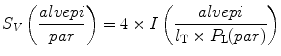
6.
Calculate the surface density of the alveolar epithelium related to the parenchyma as the reference volume (S V (alvepi/par)) by the following equation:
(see Note 23).
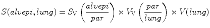
7.
The total surface area of the alveolar epithelium (S(alvepi, lung)) is given by the following equation:
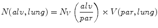
Alveolar Number
The background of alveolar number estimation is far beyond the scope of this chapter. Readers should refer to ref. (28–30).
![$$ {N}_{V}\left(\frac{alv}{par}\right)=\frac{B}{[2\times n\times a(frame)\times h]}$$](/wp-content/uploads/2016/04/A212128_2_En_18_Chapter_Equh.gif)
1.
Generate a row of consecutive thin sections of defined thickness (here: 1.5 μm) from the methacrylate-embedded samples (see Note 24).
2.
Choose the first and the fourth section and mount them in parallel on one glass slide. This pair of sections is considered a physical disector with a height (h) of 4.5 μm (distance from the top of the first to the top of the fourth section) (see Note 25).
3.
Perform an elastic fiber stain, e.g., orcein for staining the alveolar opening rings.
4.
Sample FOV at ×20 using systematic uniform random sampling on the first section. Note that the FOV consists of two corresponding images, one from each section.
5.
Project an unbiased counting frame with a defined area a(frame) onto the disector pair (see Note 26).
6.
Compare the two corresponding images and count bridges (B) defined as a complete juncture between the edges of two alveolar septa leading to a closure of the alveolus. As the alveolar entrance is surrounded by a ring of elastic fibers, the edges of these rings appear as dark stained profiles (alveolus open). Count in both directions, meaning that bridges on both images have to be taken into consideration (see Note 27).
8.
The numerical density of alveoli per unit reference volume (parenchyma) is given by the following equation:
9.
The total number of alveoli per lung is obtained by multiplication of the numerical density by the reference volume:
Alveolar Size: Number-Weighted Mean Volume
1.
Determine the total volume of alveolar airspace per lung V(alvair, lung) as mentioned above.
2.
Compute the number-weighted mean volume ( ) of alveoli using the following equation:
 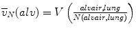 .
.
) of alveoli using the following equation: .Alveolar Size: Volume-Weighted Mean Volume
Determination of the volume-weighted mean volume of alveoli is based on the method of point-sampled intercepts (24). As larger alveoli have a greater chance of being analyzed by the point sampling process, this parameter is termed volume-weighted. This parameter also reflects heterogeneity in the distribution of alveolar volumes. The number- ( ) and the volume-weighted (
 ) mean volumes are related to each other by the equation:
 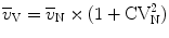 with CVN being the coefficient of variation.
) and the volume-weighted () mean volumes are related to each other by the equation: with CVN being the coefficient of variation.The theoretical background is beyond the scope of this chapter so that readers are referred to refs. (31, 32).
1.
Perform an elastic fiber stain, e.g., orcein to facilitate identification of the alveolar entrance rings.
2.
Sample FOV at an objective lens magnification of ×10.
3.
Project a test point located in the center of a test line on each FOV.
4.
If the test point hits an alveolar lumen, perform a measurement along the test line from one wall of the alveolus to the other (l i). Should the alveolar opening towards the alveolar duct be visible, a partitioning is needed. Draw a straight line between the dark stained elastic fibers located at the free edges of the septal walls, indicating the entrance to the alveolus. Perform a measurement from this entrance to the alveolar wall along the test line.
5.
Apply the following equation to estimate the volume-weighted mean volume of the alveoli: 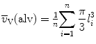 .
.
. 3.5.2 Transmission Electron Microscopy
Volume of Different Cell Types of Alveolar Septa
1.
Prepare ultrathin sections from the epoxy resin-embedded tissue blocks and stain them with uranyl acetate and lead citrate to enhance the contrast.
2.
 Histochemical Detection of Lipid Droplets in Cultured Cells
Environmental Scanning Electron Microscopy Gold Immunolabeling in Cell Biology
Histochemical Detection of Lipid Droplets in Cultured Cells
Environmental Scanning Electron Microscopy Gold Immunolabeling in Cell Biology
 Colocalization Analysis in Fluorescence Microscopy
 Atomic Force Microscopy Functional Imaging on Vascular Endothelial Cells
 Imaging Non-fluorescent Nanoparticles in Living Cells with Wavelength-Dependent Differential Interference Contrast Microscopy and Planar Illumination Microscopy
 Environmental Scanning Electron Microscopy in Cell Biology


Stabilize the sections in the TEM at low magnification for approximately 15 min. (see Note 29).
Related posts:
Histochemical Detection of Lipid Droplets in Cultured Cells
Environmental Scanning Electron Microscopy Gold Immunolabeling in Cell Biology
Colocalization Analysis in Fluorescence Microscopy
Atomic Force Microscopy Functional Imaging on Vascular Endothelial Cells
Imaging Non-fluorescent Nanoparticles in Living Cells with Wavelength-Dependent Differential Interference Contrast Microscopy and Planar Illumination Microscopy
Environmental Scanning Electron Microscopy in Cell Biology
Stay updated, free articles. Join our Telegram channel
Full access? Get Clinical Tree
