Fig. 8.1
The definition of GTV, CTV, ITV, and PTV. GTV gross tumor volume, CTV clinical target volume, ITV internal target volume, PTV planning target volume
8.2.2 Real-Time Tumor Tracking
The most commonly used method of real-time online tumor tracking is the CyberKnife Synchrony system. With real-time tumor tracking, the GTV is expanded to a CTV and then to a PTV and results usually in a total margin from the GTV to PTV of 5–8 mm. An ITV is not required. The CyberKnife (Fig. 8.2) is a frameless image-guided radiotherapy system involving a 6 MV x-band linear accelerator mounted on a robotic arm, which possesses six degrees of freedom of motion. The imaging system consists of 2 diagnostic X-ray sources mounted to the ceiling paired with amorphous silicon detectors to acquire live digital radiographic images of the tumor, or tumor localizing surrogates such as the skull, spine, or fiducial markers. The Synchrony system enables 4-dimensional real-time tracking of tumors that move with respiration. An advantage of the Synchrony subsystem is that the patients can breathe normally. Synchrony combines non continuous X-ray imaging of internal fiducial markers as surrogates for the tumor position, with a continuously updated external breathing signal. In more recent system versions, it is possible to track the tumor directly in the X-ray images (in certain very specific circumstances) using the contrast between tumor and surrounding lung tissue, thereby removing the need to implant fiducial markers. A correlation model that relates the external breathing signal with the motion of the tumor provides a real-time update of the beam position that is fed to the robotic arm on which the linear accelerator is mounted. In the treatment room, the patient is placed in a supine position on the couch in the vacuum mattress. Three light-emitting diodes (LEDs) are placed on the patient’s chest or abdomen to provide the external breathing signal. The motion of these LEDs due to respiration is registered by a digital camera array (the Synchrony camera) (Fig. 8.2). Initial patient alignment is conducted by the X-ray image-guidance system and the remotely controlled treatment couch, such that the extent of the respiratory motion is within the translational limits of the robot. The tumor is localized by reconstructing the 3D position of the tumor or the fiducial markers, which are automatically segmented in the X-ray images. The reconstructed position is compared with the position in the planning CT scan (Fig. 8.3). Just prior to the start of the irradiation, the correlation model is built by acquiring approximately 8 X-ray image pairs at different phases of the breathing cycle (Fig. 8.4). The Synchrony system makes a correlation model that relates the movement of the tumor or the fiducial markers and the LEDs. Non linear models are used to account for hysteresis in the tumor trajectory. Using this model, the linear accelerator can continuously track the motion of the tumor via the motion of the LEDs. The correlation model is intermittently validated and updated throughout treatment by acquiring new X-ray image pairs (typically every 1–6 min at our site). After each image-pair acquisition, the correlation model error is displayed on the system console. This measures the distance between the tumor position detected from the new images and the expected position based on the current correlation model. If the correlation model error is larger than 5 mm, a system interruption is generated and the operator has to build a new model. Otherwise, the new tumor position and corresponding LED positions are added as a new data point into the existing set of correlation model data points, and the model is regenerated such that the model adapts during each treatment fraction to changes in the internal external motion correlation [13–18]. Tumor tracking during respiration can be done in two ways using the CyberKnife system: one way is with the use of digital radiographic images of the tumor with the Xsight lung system and the other way is with the use of fiducial markers. The Xsight lung system was commercially released in 2006 and has been updated twice since then by the vendor. Clinical experience with the latest algorithms is currently limited. On the other hand, several CyberKnife users did report on the technique to place fiducials based on extensive clinical experience. In total, five different techniques are available to place markers: (1) bronchoscopic, (2) percutaneous intrapulmonary, (3) percutaneous extrapulmonary, (4) intravascular, and (5) bronchoscopic with electromagnetic navigation.
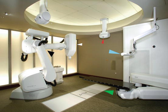
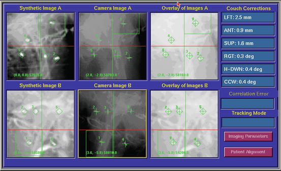
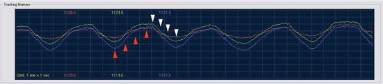
Fig. 8.2
The CyberKnife. White arrow, linear accelerator; black arrow, robot; red arrow, one of the 2 X-ray tubes; green arrow, one of the 2 flat panels; blue arrow, Synchrony camera
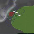
Fig. 8.3
Alignment of the tumor with the use of implanted fiducial markers. A screen dump of the digital display at the CyberKnife treatment console taken before treatment in order to align the tumor. In the first column, the DRR is shown. In the green cubes, the markers on the DRRs are shown. In the second column, 2 orthogonal images of the patient are shown. The green crosses indicate the marker positions detected automatically by the tracking software. The offsets between the target centroid position in the treatment plan and that calculated from the live X-ray images are shown under the heading “Couch Corrections.” Initially this information is used to automatically adjust the couch position. Once treatment starts, the couch remains static and all tracking is performed using the robotic arm and LINAC. The third column shows an overlay of the DRRs and the X-ray images after the calculated offsets are applied
Fig. 8.4
The timing of imaging to calculate tumor trajectory in three dimensions. Green, blue, and purple lines: breathing cycle as recorded with the Synchrony camera; red arrows, imaging during expiration; white arrows, imaging during inspiration. In reality the image acquisitions are spaced over multiple breathing cycles and can be timed automatically by the Synchrony system to ensure that the entire respiratory cycle is evenly sampled
8.2.3 CT-Based Internal Gross Tumor Volume (ITV)
The movement of tumors in the lung depends on their location within the lung. These tumors often move by more than 1 cm and sometimes as much as 3 cm during deep inspiration or expiration. The reduction of margins with a CT-based ITV is based on the individual movement of the tumor. A tumor that is moving less than one centimeter will thus get a smaller margin than a tumor that is moving more than 1 cm. A CT-based ITV is preferably outlined on the expiratory phase of the 4 D images and registered with the outline on other respiratory phases to create a union of target contours enclosing all possible positions of the target (an ITV). Another method is to create an image of maximum intensity projection by combining data from the multiple CT data sets with data from the whole-breath cycle and modify tumor volume by visual verification of the target volume throughout the breathing phases. In this case, the ITV should consist of the GTV plus a margin to account for microscopic disease (8 mm). Even with 4D-CT, the free-breathing simulation is only a snapshot and a single stochastic sampling of the patient’s respiratory cycle. Attention should be paid to irregular breathing and variations in the patient’s breathing pattern over the course of each treatment session and the entire treatment course and to the effects of these irregularities on the ITV margin [19]. If 4 D CT is not available, an ITV can be developed based on breath-hold spiral CT images that require the patient to hold his/her breath once during the simulation at the end of expiration and once at the end of inspiration, but not during treatment delivery. In this procedure, images are acquired through the use of a standard extended temporal thoracic CT protocol. In this protocol, patients are asked to breathe normally, and the extended temporal CT images are acquired at the beginning of the simulation; the isocenter is then set. Subsequently, images are obtained by using a fast CT simulation protocol while at the end of inspiration and expiration. Separate GTVs and CTVs should be delineated by a physician both on the end of expiration CT image set and on the end of inspiration image set. An ITV is then generated by combining the two CTVs on the extended temporal CT scan to form an ITV that includes the entire path of the CTV as it moves from inspiration to expiration. Normal tissues should be contoured in the extended temporal CT images as well. The ITV will be superimposed on the slow CT images, which will serve as the basis for treatment planning [20].
8.2.4 Forced Shallow Breathing with Abdominal Compression
The patient is immobilized in a stereotactic body frame (Fig. 8.5). This usually consists of a vacuum pillow and a rigid frame with a laser system attached for positioning and a diaphragm control device. Several small tattoos are placed on the patient’s chest for repeated positioning. A pressure can be applied to the upper abdomen using the diaphragm control device. This device consists of an abdominal plate and a screw that is attached to the body frame (Fig. 8.6). The pressure on the upper abdomen is regulated by adjusting the height of the plate with the screw (Fig. 8.7). The patient is now only able to have shallow breathing. Margin reduction from CTV to PTV is possible because on one hand the tumor will move less than 1 cm due to the shallow breathing and on the other hand due to the exact immobilization with the whole body frame and the abdominal compression [21–24].
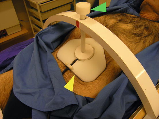
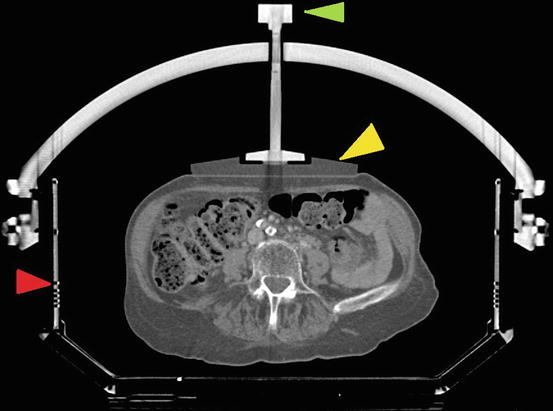
Fig. 8.5
The whole body frame with abdominal immobilization. Green arrow, the whole body frame; red arrow, the abdominal compression plate
Fig. 8.6
A detailed picture of the whole body frame with abdominal immobilization. Yellow arrow, abdominal plate; green arrow, screw to regulate the degree of abdominal compression
Fig. 8.7
A CT scan slice through the whole body frame. Red arrow, the whole body frame; yellow arrow, abdominal plate; green arrow, screw to regulate the degree of abdominal compression
8.2.5 Breath-Hold Methods
With the breath-hold methods, the CTV to PTV margin is reduced because radiation is only delivered when the tumor is not moving during the breath hold. This method is also called the deep inspiration breath-hold technique (DIBH). Barnes et al. found that, on average, self-gated DIBH decreased the percent of lung volume receiving 20 Gy (V20) from 12.8 to 8.8 % with GTV-to-PTV margin reduction [25].
In the DIBH technique, the patient is initially maintained at quiet tidal breathing, followed by a deep inspiration, a deep expiration, a second deep inspiration, and breath hold. At this point the patient is at approximately 100 % vital capacity, and simulation, verification, and treatment take place during this phase of breath-holding. Different methods have been implemented based on this principle. To monitor lung inflation levels, the patient breaths through a mouthpiece connected to a differential pressure pneumotachograph spirometer or modified ventilator interfaced to a laptop computer to monitor the air flow. A nose clip is used to prevent nasal breathing [26–28]. If the patient is at the right inspiration level, the therapist can turn on the beam. With another method, the patient controls an interlock of a modified linear accelerator if he/she reaches the right inspiration level. The therapist turns on the beam when the patient judges that he/she has attained the correct breath-hold level (=self-gated DIBH). To familiarize the patient with the procedure, a training session is given a few days before the planned simulation. Breath-holding techniques may be poorly tolerated by patients with mediocre lung function, and active patient and therapist participation is often required [29].
8.2.6 Respiratory Gating Methods
The ITV is smaller because irradiation of the tumor only occurs during a certain phase in the breathing cycle. A device monitors patient breathing and allows delivery of radiation only during certain respiratory phases, synchronous with the patient’s respiratory cycle. Several devices have been developed; however, the real-time position management respiratory gating system (RPM) is most commonly used [30–32]. This system uses two passive reflective markers that are placed on the patient’s chest or abdomen. An illuminator sends infrared light to the reflective markers and the markers send the light back to a video camera. The respiratory movement is tracked by the upper marker; the lower marker calibrates the system. A computer processes the video signals and sends on-off control signals to the linear accelerator. The patient has to breathe regularly and stably during simulation and treatment. At the start of the simulation and the irradiation, the minimum and maximum position of the upper marker is determined by recording a few breathing cycles [33]. The planning CT scan must be acquired in the same phase of the breathing cycle as the treatment.
8.3 Simulation, Treatment Planning, Constraints, and Prescription
The simulation depends on the radiation therapy technique as is explained in Chap. 6. Usually, the patient is simulated and treated in the prone position with or without a vacuum mattress to minimize motion of the patient. The treatment planning CT scan is performed with intravenous contrast, usually with a wide-bore multi-slice computed tomography (CT) simulator. The use of 4D CT scans, exhale or inhale CT scan combined or not combined with a contrast enhanced planning CT scan, depends on the radiation technique (see Chap. 6). The patient is scanned from his/her teeth to the middle of his/her abdomen, and the trans axial imaging has a slice thickness of 1.5–3 mm.
The planning CT is transferred to the treatment planning system (TPS). The tumor and organs at risk (OAR) are then contoured. The gross tumor volume (GTV) is contoured using the lung window. Margins to the GTV are added depending on the radiation technique (see Chap. 6). The OAR consist of both lungs, esophagus, the heart, and the spinal cord.
Usually, inverse treatment planning is used; however, the treatment plan can also be calculated using forward planning, and depending on the radiation technique, the number of beams varies between 7 and 15 using conventional IG-IMRT techniques or up to 150 beams using stereotactic radiotherapy with the CyberKnife. The total dose is prescribed to the isodose surface that covers 95 % of the volume of the PTV. The total dose depends on the fractionation scheme (see Chap. 5 and 6). The dose to normal tissues (lungs, heart, spinal cord, etc.) should be within the constraints. An example of dose constraints to the OAR using different treatment schedules is shown in Table 8.1. Two opposite (90°) digitally reconstructed radiographs (DRRs) are generated to align the patient correctly; however, also this depends on the radiation technique.
Table 8.1
Dose constraints
Dose constraints for | 1 fraction | 3 fractions | 5 fractions | 7 fractions | |
|---|---|---|---|---|---|
Organ | Volume | Dose (Gy/fr) | Dose (Gy/fr) | Dose (Gy/fr) | Dose (Gy/fr) |
Spinal cord | Any point | 12.5 | 6 | 5.5 | 4.5 |
Esophagus | Any point | 13 | 7 | 7 | 6 |
Heart | Any point | 15 | 12 | 10 | 8 |
Trachea and main bronchus | Any point | 16 | 10 | 10 | 8 |
Plexus brachialis | Any point | 14 | 8 | 6 | 5 |
Liver | Any point | 30 | 20 | 12 | 8 |
Lung | V20 (EQD2) | <31 % | <31 % | <31 % | <31 % |
8.4 Clinical Outcome of Primary Lung Tumors
8.4.1 Introduction
Stereotactic body radiotherapy (SBRT) targets and delivers high ablative doses of radiation to sites within the body while applying methods to reduce the effects of tumor motion to help assure accuracy and precision, as described in Chap. 6. However, caution must be taken if the tumor is close to organs at risk such as the trachea, mainstem bronchus, esophagus, or heart. Serious complications, including death following bacterial pneumonia, pericardial effusion, radiation pneumonitis, or massive hemoptysis, have been reported [34, 35]. Therefore, the tumors are classified into two groups: the peripheral tumors and the central tumors. Although there are several definitions, central tumors are tumors located <2 cm from the trachea, mainstem bronchus, main bronchus, or esophagus, as well as tumors located close to the heart and tumors located in the mediastinum.
SBRT to peripheral tumors has resulted in high local tumor control rates [9–11]. An example of an excellent local control in one patient is shown in Fig. 8.8. Less experience exists in SBRT for central lung tumors because they are relatively rare and because common SBRT dosing schedules, such 3 fractions of 20 Gy, cannot be safely used due to the proximity of the trachea, mainstem bronchus, esophagus, or heart. By increasing the number of fractions to 5, 8 or even 10 and reducing the fractional dose, some groups have reported successful treatment of central lung tumors with minimal complications [36]. However, some authors did report grade 5 toxicity related to the treatment [34, 37–39].
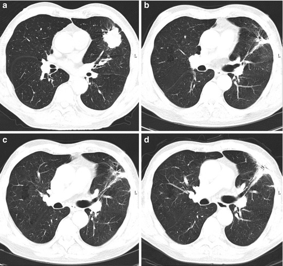
Fig. 8.8
T2 N0 NSCLC before the treatment (a) and the clinical result after 1 year (b), 2 years (c), and 3 years (d). Note pulmonary fibrotic change
8.4.2 Peripheral Tumors
Although many articles did report the outcome of stereotactic radiotherapy of peripheral tumors, a randomized trial comparing surgery or different methods of radiation delivery has not been done. Treatment schedules with single fractions were mainly used in the beginning but are still used by some radiation centers. Whyte was one of the first to report his/her results with a single fraction of 15 Gy in a phase I clinical trial [40]. Later on, dose escalation studies were done [30, 34]. Hara et al. reported a 2-year local control rate for patients receiving a single fraction of 30 Gy or more of 83 % compared to 52 % in those treated with a single fraction less than 30 Gy [30]. However, Hof et al. concluded that single fraction SRT was a safe and effective treatment option for patients with small tumors but that the application to larger tumors was unclear [41]. While these articles did appear, other articles did report the outcome of multiple fractions. The most commonly used schedule for peripheral tumors is one with 3 fractions of 18-20Gy, but schedules with 4 or more fractions also exist.
The first three most important articles are from Timmerman et al., Onishi et al., and Wulf et al. [9, 42, 43]. Timmerman et al. performed a dose escalation study with inoperable early-stage lung cancer patients. He started with 24 Gy in 3 fractions and escalated the dose at 2 Gy per fraction [42]. Patients with T1 vs T2 tumors underwent separate independent dose escalations. Thirty-seven patients were enrolled and both T-stage groups ultimately reached and tolerated 60 Gy in 3 fractions. The maximum tolerated dose for this therapy in either T-stage group was not reached. Tumors responded to treatment in 87 % of patients (complete response, 27 %). After a median follow-up period of 15 months, 6 patients experienced local failure, all of whom had received doses of <18 Gy per fraction since February 2000. One patient experienced grade 3 pneumonitis and another patient had grade 3 hypoxia. Onishi et al. reported in 2004 the clinical outcome of a Japanese multicenter study [9]. Two hundred forty-five patients with stage I NSCLC (T1N0M0, n = 155; T2N0M0, n = 90) were treated with hypofractionated high-dose stereotactic radiotherapy in 13 institutions. Stereotactic three-dimensional treatment was performed using non-coplanar dynamic arcs or multiple static ports. A total dose of 18–75 gray (Gy) at the isocenter was administered in 1–22 fractions. The median calculated biologic effective dose (BED) was 108 Gy (range, 57–180 Gy). Local progression after a median follow-up of 24 months occurred in 14.5 %, and the local recurrence rate was 8.1 % for BED ≥100 Gy compared with 26.4 % for <100 Gy (p < 0.05). The 3-year overall survival rate of medically operable patients was 88.4 % for BED ≥100 Gy compared with 69.4 % for <100 Gy (P < 0.05).
Wulf et al. compiled the results of several studies. They included both lung metastases (n = 56) and primary lung tumors (n = 36) [43]. Twenty-four patients receiving 3 × 10 Gy, 22 patients receiving 3 × 12.5 Gy, and thirty-one patients receiving 1 × 26 Gy had 2-year local control rates of 71, 92, and 100 % respectively. After a median follow-up of 14 months (2–85 months), 11 local recurrences were observed with significant advantage for higher doses. These 3 studies did show the efficacy of a biologically effective dose (BED) of 100 Gy or more, and therefore, these are the most used schedules with 3 fractions of 17–20 Gy. With the current techniques as described in Chap. 6, the 2-year local control is 93 % or more (see Table 8.2). The 2-year overall survival varies between 58 and 91 %, but depends on patient selection as most treated patients are not candidates for surgery due to their comorbidities as cardiovascular and pulmonary diseases (see Table 8.3).
Table 8.2
Local control after treatment for early-stage lung cancer, peripherally located
Technique | Number of patients | Total dose | Number of fractions | Local control at 2 years (%) | Author |
|---|---|---|---|---|---|
Real-time tumor tracking | 70 | 60 | 3 | 96 | Van der Voort et al. [10] |
Real-time tumor tracking | 20 | 42–60 | 3 | 95 | Vahdat et al. [44] |
CT-based ITV
Related posts: Stereotactic Body Radiotherapy for Oligometastasis
Stereotactic Body Radiotherapy for Bone and Soft Tissue Sarcoma Stereotactic Body Radiotherapy for Oligometastasis
Stereotactic Body Radiotherapy for Bone and Soft Tissue Sarcoma
 Stereotactic Body Radiotherapy (SBRT) for Pancreatic Cancer Stereotactic Body Radiotherapy (SBRT) for Pancreatic Cancer
 Planning and Dosimetry for Stereotactic Body Radiotherapy Planning and Dosimetry for Stereotactic Body Radiotherapy
 Stereotactic Body Radiation Therapy to Liver Stereotactic Body Radiation Therapy to Liver
 Stereotactic Body Radiotherapy in Head and Neck Cancer Stereotactic Body Radiotherapy in Head and Neck Cancer
Stay updated, free articles. Join our Telegram channel
Full access? Get Clinical Tree
 Get Clinical Tree app for offline access

|