3
Technical Aspects of Brachytherapy
Mandar S. Bhagwat, Ivan M. Buzurovic, Antonio L. Damato, Scott A. Friesen, Jorgen L. Hansen, Desmond A. O’Farrell, Emily Neubauer Sugar, and Robert A. Cormack
Although brachytherapy with radium sources was the original form of radiation therapy, radiation therapy has grown to use a variety of radioactive materials and radiation-producing devices, leaving brachytherapy as a relatively small subspecialty of radiation oncology. This section reviews a number of technical components of a brachytherapy practice.
SOURCES
Brachytherapy can use any variety of radioactive materials to create sources to deliver radiation. Radioactive sources, or seeds, can be permanently or temporarily placed inside the tumor to give a therapeutic dose. The dose is deposited when the radioactive isotopes decay. Medical isotopes are constructed with a radioactive core inside a sealed capsule. The properties of isotopes used in brachytherapy sources are listed in Table 3.1 (1–5).
Radium was the first isotope used in brachytherapy and for a long time brachytherapy doses were prescribed in terms of the equivalent radium dose. The loading of radium needles formed the basis of interstitial implant dosimetry. Needles were made with uniform activity or with higher activity at one or both ends (1). The radium could be distributed uniformly, which would result in higher dose in the center of a treated volume (known as the Manchester system), or nonuniformly to create a uniform dose distribution (known as the Paterson−Parker system) (2).
These philosophies of how to place the sources continue today when other isotopes are used. Iodine-125 (125I) and palladium-103 (103Pd) are often placed nonuniformly in the prostate to achieve full coverage of the gland by the prescription dose. In permanent prostate implants, seeds are often loaded peripherally to achieve this coverage while keeping the urethra, at the center of the gland, from getting too much dose.
Table 3.1 includes the characteristics that determine how brachytherapy sources are deployed. The energy predominantly determines whether the sources will be used as a permanent implant or temporary implant. The attenuation of the low-energy photons by patient tissue allows some isotopes, such as cesium-131 (131Cs), 125I, or 103Pd that emit low-energy photons when they decay, to be permanently placed without creating a radiation safety hazard for medical staff or the general public. Isotopes such as 137Cs, iridium-192 (192Ir), and cobalt-60 (60Co) release high-energy photons that are much more penetrating. These isotopes are used in a temporary implant approach where the sources are placed in an applicator and removed after the time needed to deliver the therapeutic dose. Temporary implants should occur in an environment where adequate shielding is present to meet radiation safety goals (6).
Table 3.1 The relevant characteristics of a number of isotopes used in brachytherapy sources

PERMANENT IMPLANTS
Manual Implants
Brachytherapy sources may be permanently placed in the area of the tumor after resection. Sources may be placed individually, in groups as part of a suture, or stitched into a mesh. Both suture and mesh may be used to ensure the desired spacing as seen in Figure 3.1. Placement is done in the operating room without treatment planning. After sources have been deployed, dose can be evaluated by reconstructing the distribution of sources from CT scans. Postoperative treatment planning allows evaluation of the dose distribution achieved during the process and doses received by surrounding organs at risk (OAR).
Image-Guided Prostate Implants
Permanent prostate implants represent one of the more advanced image-guided approaches to brachytherapy. Prostate implants are usually guided by transrectal ultrasound. An ultrasound probe is inserted in the rectum in order to visualize the prostate, urethra, and anterior rectal wall while implanting sources. A template is set up against the perineum and the clinician places needles containing seeds and nonactive spacers, which are used to separate the seeds and help create a specific pattern of seeds. Real-time ultrasound visualization of the needles allows the clinician to verify that the needles are placed according to plan.

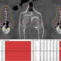
Figure 3.1 A permanent implant involves the placement of sources during a surgical procedure. The surgeon and brachytherapist determine the appropriate size of the implant. (A) 125I brachytherapy sources are incorporated in biodegradable strands at 1 cm spacing. The strands are stitched onto a biodegradable mesh to ensure spacing between strands. The mesh is then placed in the patient. (B) A digitally reconstructed radiograph created from a CT acquired after the procedure. The CT is used to determine the final configuration of the sources in the patient. (C) The CT is used to determine the location of the brachytherapy sources and calculate the achieved dose. The sources also provide a means of registering CT and MR images, which allows dose to be displayed on MR images.
Prostate implants are generally indicated for patient with a gland size of 20 to 60 cc. Using a two-stage planning technique, the volume of the prostate can be determined prior to implant via a volume study, where an ultrasound is taken with the patient in the same position he will be in for the brachytherapy treatment. A measurement of the height, width, and length of the prostate can be used, or a contour from a three-dimensional (3D) ultrasound scan of the prostate can be used to calculate the volume.
Once the volume is determined, the activity and number of seeds that will be necessary can be calculated using a nomogram. Nomograms are usually linear (y = ax + b) or power (y = axb) equations that predict the number of seeds used or total activity implanted based on the preimplant volume. These are developed by collecting data for a set of patients and plotting the number of seeds used or total activity versus volume and fitting a function to the data. In this way, individual institutions may develop their own nomograms (7). After the volume study, a preplan can be developed on the ultrasound. The doctor contours the prostate, urethra, and rectum in the treatment-planning system. Afterward, a dosimetrist plans needle and seed positions, based on a model of the template that will be used for the implant. The depth of each needle is determined with respect to the deepest implantable slice or plane in the prostate, called the base plane.
With a preplan, the seed and spacer configurations can be ordered from the vendors as preloaded needles. The advantage is that the needles can be built with stranded seeds, which have been shown to prevent seed migration (8). This method then requires precise placement of the needles during the implant so that the planned dosimetry is achieved in the patient.
An alternate to the preplanning method is to live plan in the operating room (9,10). This requires the ability to build the needles during the procedure. For a live plan, an ultrasound scan is taken with the template in place. The clinician draws contours on the scan and a live plan is generated. Many planning systems contain optimization algorithms that choose needle and seed positions based on the dose constraints given for coverage versus OAR (in this case, the urethra and rectum). This allows for quick optimization of the plan while under the time pressure of an operating room environment. Once the plan is approved by the doctor, the needles can be built.
Several systems on the market can be used for building and delivering the needles. These include the Mick applicator,a the BARDb source link, and the Nucletron SeedSelectron.TMc The Mick applicator has a magazine where seeds are placed for insertion into the needle. Cartridges are used to load the magazine during the procedure. Then the applicator is attached to the needle and the seeds are pushed inside. The physician retracts the needle and uses a plunger to deposit each seed into position inside the prostate (2). The BARD source link uses cartridges of seeds and linkable spacers that put together seed trains that are linked like stranded seeds. The clinician then manually places each needle in the patient. If the clinician does not wish to manually deliver the seeds a remote afterloading device like the SeedSelectron can be used. The SeedSelectron can be connected to the needle via a sterile tube after placement, and its motorized capability can build seed spacer trains from cartridges and push them into the needle with a guidewire through the tube.
Regardless of the ways in which the seeds are deposited, the goals for planning are generally the same. Dose distributions are often summarized in terms of the dose that 90% of the prostate receives (D90), and the high-dose regions of the normal structures such as the volume of a structure receiving either 100% or 150% of the prescription dose (V100 or V150).
TEMPORARY IMPLANTS
Temporary implants can be either low dose rate (LDR), pulsed dose rate (PDR), or high dose rate (HDR). In the modern era, sources are generally placed using an afterloading approach where an applicator is placed in the region of interest and the sources are then deployed into the applicator. The applicator may be as simple as a single catheter used for an endobronchial treatment, a series of interstitial needles placed for a volume implant or a tandem, and ovoids where the applicator is composed of a number of parts with adjustable geometry as seen in Figure 3.2. In each case, the applicator is placed in the region of concern and dose is delivered by a source introduced into the applicator some time after applicator placement.
Low Dose Rate
LDR implants typically involve introducing afterloaded sources into the patient for periods of hours to days. Typical doses rates are 40 to 70 cGy/hr. Isotope-containing devices are introduced into the patient and are positioned under visual or image guidance. Such applicators or catheters can be placed by interstitial, intralumenal, or intracavitary surgical methods. Plans are then generated either via software or by the use of published tables or nomograms, optimizing the isotope positions and source activity. When the source configuration appears dosimetrically satisfactory, sources may be placed. An LDR technique is a tandem and ovoid treatment for cancer in an intact cervix using 137Cs. The tandem is placed transvaginally through the cervical os and into the uterus. The length and angulation of the tandem are determined by the individual’s anatomy. Concurrently, ovoids are placed in the lateral vaginal fornices. Dummy markers acting as inert proxies for the isotope are placed and the patient is imaged. Target areas and normal tissues are defined as the virtual positions of the sources. LDR sources selected from the available inventory are virtually added to the dummy positions until the resultant dose configuration is satisfactory to the physician. The appropriate sources can be manually afterloaded into the tandem and ovoid device with the patient in a room with appropriate shielding.

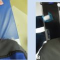
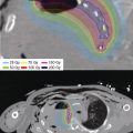
Figure 3.2 (A) A CT and MR compatible tandem and ovoid applicator composed of plastic and carbon fibers. The applicator has variable configurations with different tandem lengths and curvature as well as variable ovoid separation and multiple ovoid sizes. (B) A coronal CT scout of the applicator in place. The applicator itself is not well visualized on planar images, but dummy markers are placed to assist in localizing the applicator and source locations. (C) A tandem and ovoid visualized in the treatment planning system. The applicator channels are represented in light blue, and potential source locations are within the channels. The target volume, bladder, rectum, and sigmoid are red, yellow, brown, and blue, respectively. The treatment planner has determined the time the source spends at each dwell location to meet the clinician’s dosimetric goals.
High Dose Rate
HDR is delivered with a single high-activity source as opposed to using a number of LDR sources. The source is delivered by a computer-controlled afterloader, which can position the source at a number of different locations within the applicator. Each of these positions is known as a dwell location, and the time that the source spends at that location is known as the dwell time.
From the planning standpoint, HDR is similar to LDR. However, the time the HDR source spends at a particular position can be controlled in the planning process. One can increase or decrease the dwell time of a source position to modulate the dose in a very local fashion. Although, as with all forms of brachytherapy, good geometry is essential for good outcomes, HDR can compensate, within reason, for slightly less than optimal geometry. Consider two needles intended to be inserted into a patient 1 cm apart. If at planning it is noticed that the needles bow out in the middle and get closer at the tips, dwell times can be increased where they bow out and decreased at the tips to achieve the originally planned dose distribution.
Pulsed Dose Rate
Technically, a PDR implant may be considered an HDR implant using a source of lower strength. From a radiobiological view, it is an attempt to approximate an LDR treatment schedule and radiobiology, but HDR treatment in terms of optimization. As in HDR, the source is delivered to a series of dwell locations for the appropriate dwell time. However, instead of a small number of fractions of a few Gray each, PDR uses numerous small fractions to mimic the average dose rates seen in LDR implants, but with the computer control available in HDR methods. The unit allows the delivery of time-modulated dose distribution in short bursts typically a few minutes per hour. Although the treatments must be delivered in a shielded environment, the treatment source is shielded most of the time. This delivery pattern facilitates patient care over the duration of the implant.
APPLICATORS
Over the years, brachytherapists and equipment manufacturers have developed an extensive array of applicators for use in afterloading techniques. In most cases, the applicator is imaged after insertion for treatment-planning purposes. All reusable applicators should be quality assessed on a regular basis. Plastic applicators may have a shorter useful life than metal applicators and be more prone to radiation damage. In busy practices, budgets should be planned to be able to accommodate an ongoing applicator replacement program. Four common applicator types are briefly described to highlight some aspects of their use.
Fixed Geometry: Vaginal Cylinder
Because vaginal cylinders are a fixed geometry and the relevant treatment region may be defined with respect to the applicator surface, treatment plans are often developed without imaging of the applicator in the patient, based on cylinder diameter and treatment length. Cylinders are used to create a reproducible geometry so that the treatment is characterized by the dose delivered at the surface of the applicator, or at a depth in tissue from the applicator. The bulk of the applicator is plastic surrounding a source channel of plastic or metal. As cylinders come in a limited number of diameters, a library of treatment plans may be used to facilitate the treatment-planning process. Because the geometry of the applicator should not change from fraction to fraction, a single treatment plan can be used for multiple applications. Given the high-dose gradient in brachytherapy, care must be taken to ensure the same diameter applicator is used with the appropriate treatment plan. Diameter verification can be provided by independent physical measurement of the cylinder, placing radiopaque markers in the applicator to indicate size in conjunction with magnification rings and planar imaging, or measuring the applicator diameter from volumetric scans such as CT as shown in Figure 3.3.
Fixed Geometry: Surface Devices
For small, flat superficial lesions the use of standard rigid applicators that come with diameters of 2 to 5 cm may be possible. These are cone shaped and are clinically placed over the lesion and a peripheral margin. The source may be an electronically generated low-energy X-ray of 50 to 80 kV as used in electronic brachytherapy (EBT) or an HDR 192Ir 380 keV source. For the former, look-up tables of exposure times versus depth dose can be developed. Similarly, for HDR, which is often used for larger lesions, plans can be accumulated in a library of standard configurations using treatment-planning software. Additional optimization will be necessary to deal with curve- or complex-shaped surfaces and depths.
Variable Geometry: Tandem and Ovoids
Most applicators are not like cylinders, and require imaging and planning due to variations in applicator geometry from placement to placement.
Tandem and ovoids were historically used with LDR implants. The devices were made of metal and could include shielding in the ovoids to reduce high-dose regions in the midplane of the applicator. As brachytherapy has moved toward more image-based treatment planning, a number of plastic CT- and MR-compatible applicators have appeared on the market. To remain image compatible, these applicators do not usually have any shielding. A variant on the tandem and ovoid is the tandem and ring. The tandem component of the applicator is used to treat the uterus, while either ovoids or the ring are used to provide appropriate coverage to the cervix. Prescription dose often extends up to 2 cm from the source channel implying significantly higher central dose regions within the prescription dose envelope.
Custom Applicators: Surface Applicators
Where setup and reproducibility become a challenge, the use of custom-built applicators is appropriate (11,12). These applicators use normal anatomy both as positional landmarks and as anchor points for the treatment apparatus. One such applicator is a Freiburg Flap,d a swatch of regularly spaced flexible silicone stranded balls with a central channel through which a source-accommodating catheter can be threaded. This applicator can be cut to size and placed on the patient’s skin. Precut standard swatches in reserve ranging from 3 × 3 cm to 24 × 24 cm can quickly accommodate curved and complex clinical targets.

Figure 3.3 Sagittal plane reconstructed from the CT of a patient after cylinder placement. The CT is acquired for verification of size and position, but is not used for treatment-planning purposes.

Figure 3.4 Custom surface applicator. The process of constructing a surface applicator is shown progressing from upper left, right, lower left panels. The mold is built up and catheters are laid between layers of thermoplastic. The hand is scanned with the applicator in place for treatment planning purposes as shown in the lower right panel.
For more complex surfaces, the treatment catheters can be incorporated into a thermoplastic mold, commonly used in radiation oncology clinics and familiar to most practitioners. The catheters are placed on the outer surface of the mold and secured by adding extra strips or sheets of thermoplastic. An example of the construction process can be seen in Figure 3.4. Care should be taken to lay the catheter in such a fashion that nonnegotiable curves in the trajectory are not introduced. This can be checked by running a guidewire through the catheter and assessing resistance. Curvatures down to the curvature of a small coin will likely be accommodated. The inner surface of the mask anneals discreetly to the nose, forehead, and chin of the patient. Care to fit the mask with catheters to the patient’s face allows for faithful delivery of the planned dose over this highly variably shaped area.
TREATMENT PLANNING
A distinctive difference between teletherapy and brachytherapy is that, in the latter, sources are positioned in some configuration inside or nearby a tumor, and the geometrical relationship among sources, tumor, and OAR is essential to obtaining a satisfactory dose distribution. In this respect, one may say that the most important aspect of patient-specific treatment planning in brachytherapy is the satisfactory implantation of the needles or positioning of the applicator (intracavitary or surface). Historically, no other customized planning was performed in brachytherapy aside from deciding the source geometry. The use of a standard loading plan for a given catheter geometry provided good results, but was largely due to necessity: a lack of 3D information of tumors and OAR, and constraints on the optimization of dose rate from different source locations. The wider adoption of imaging with ultrasound (13), CT (14), and MR (15,16), and the easier optimization of source strength afforded by the different dwell times in HDR have removed these limitations and improved the therapeutic ratio. At the same time, planning systems allowing for the visualization of isodose lines and calculation of dose metrics based on tumor and organ delineations have become commonplace. More recently, commercial solutions to improve the calculation of dose in tissue by taking into account inhomogeneity have been released (17). Thanks to all these advances, it is now possible given catheter geometry to shape isodose lines to the particular needs of each patient, instead of using a formulaic approach. Nevertheless, there is still a role in some cases for standard plans, either as a starting point for customized plans, or for cases not requiring customization. Treatment planning with advanced computerized optimization strengthens and complements the applicator and implant design.
Optimization allows the shaping of the isodose lines to conform the prescription dose to the targeted area and avoid the contoured OAR. For instance, many studies in cervix brachytherapy with PDR and HDR found that patient-specific optimization results in better tumor coverage and OAR dosimetry than standard plans (18–21). Nevertheless, treatment planning cannot substitute for inaccurate catheter placement. Attempts to increase some dwell times to compensate for poor catheter placement is not feasible for two reasons. The high-dose region nearby a source would receive an unacceptably high dose, with a loss of conformity to the targeted area likely resulting in an unacceptably higher dose to normal tissue. In the previous example of cervix brachytherapy, if the lateral extension of the tumor is too large, optimization alone cannot compensate for the loss in tumor coverage, and additional needle insertion laterally should be considered (22). In HDR, PDR, and LDR procedures requiring the loading of the sources after the implantation procedure, treatment planning can be described as composed of digitization, normalization, optimization, and dose prescription. Digitization is the act of identifying possible source positions. Normalization serves to select the general size of the treatment area (eg, point A in cervix brachytherapy). Optimization modulates the source strength (LDR) or dwell time (HDR and PDR) at various locations, thus changing the shape of the isodose lines. Dose prescription selects the physical dose to associate with the 100% isodose line. Before treatment planning catheters or applicators will have been implanted, inserted, or placed, and a simulation (CT, MR, or ultrasound) will have been performed. During this session, it is crucial to create diagrams, clinical photography, and labeling to ensure the verification and reproducibility of the catheter configuration between planning and treatment delivery. After treatment planning and physician review, quality assurance of the final plan and the treatment must be performed prior to dose administration.
Treatment plans can be image based or nonimage based. In image-based treatment plans, catheters are identified in an image and digitized, and isodose lines are displayed. Image-based planning simplifies the evaluation of a plan by showing the dose distribution overlaid to the patient images; calculation of dose metrics is also possible. If standard plans are used, image-based treatment planning allows an easier evaluation of the expected normal tissue complication probability and tumor control probability. Real-time evaluation of the relationship between isodose distribution and surrounding anatomy also makes the process of plan optimization intuitive, enabling patient-specific treatment planning. Nonimage-based plans only require digitization of the correct catheter geometry. In this case, digitization is usually performed in a virtual image with no anatomic features. Nonimage-based plans are usually standard plans, as the effect of optimization on the patient cannot be easily evaluated, and involve fixed catheter geometries. Indication for image-based planning is a need for conformity to a target and/or avoidance of OAR, usually associated with prescription doses higher than the OAR tolerances; nonfixed catheter geometry (eg, an interstitial implant, a surface applicator conforming to an irregular surface); or need or desire to document the dose received by certain organs. An example of nonimage-based plans may be vaginal cuff brachytherapy with a vaginal cylinder (23): the catheter geometry is fixed (a straight line), and due to the high tolerance of the OAR compared to the prescription dose, normalization and optimization may be decided only based on applicator diameter and treatment length. When a higher dose prescription is required, as is the case for the treatment of some vaginal recurrences with a vaginal cylinder, an image-based plan would be preferable. Another example of nonimage-based plans may be a flat surface applicator prescribed 3 mm in tissue in treating a square target.
Aside from the considerations mentioned previously, the different aspects of quality assurance involved in image-based and nonimage-based planning need to be understood. Quality assurance (including a verification of correct digitization) of image-based plans is usually more time consuming than that of nonimage-based plans (which are usually standardized, and for which fixed catheter geometries are used). For this reason, moving a practice from nonimage-based planning to image-based planning will require a review of the quality management program and additional training for the staff. Conversely, the lack of anatomical information in a nonimage-based plan may be a cause of concern in some cases, as the effect of the dose distribution to the patient may be more difficult to evaluate. Each clinic needs to weigh the need for image-based planning for every treatment site taking into consideration published guidelines, available expertise, clinical practice, and optimal resource management. A detailing of the process map involved in each treatment by a multidisciplinary team may help identify possible risks associated with image-based and nonimage-based treatment planning, and may also indicate opportunities to increase efficiency in the use of clinic resources (24).
Image-Based Treatment Planning
Image-based planning allows the visualization of isodose lines overlaid on a patient’s scanned anatomy, and may be used to optimize the dose distribution to conform to the targeted area and to spare normal tissue. Clinical target volume and OAR delineation may be performed, and are commonly used in some cases such as cervix brachytherapy. All modern brachytherapy planning systems allow for the calculation of dose volume histograms and dose metrics to improve the evaluation of a plan and facilitate treatment optimization. Guidelines for various sites recommend the analysis of patient-specific dose metrics during planning. In particular, the dose distribution can be tailored to a contoured clinical target volume (CTV). Given clinical positioning of the catheters in or by the tumor, the use of additional planning margins around the CTV akin to planning target volume (PTV) margins for external beam planning is not recommended. Furthermore, the use of planning margins in planes perpendicular to the brachytherapy catheters may reduce the ability to spare OAR and is discouraged (25). Use of planning margins in the direction of the catheters (typically in the superior–inferior direction for interstitial insertions) is not associated with an increase in heterogeneity. Some authors (26,27) have reported using margins in the superior–inferior direction for prostate and for gynecological HDR brachytherapy. Although there is no consensus on the need and on the appropriate extent of such margins, the potential lack of conformity to the CTV should also be weighed against possible consequences to the normal tissue. Image-based HDR and PDR plans can be optimized to achieve a desired dose distribution, and the high-dose gradient typically involved in brachytherapy may result in significantly different dose metrics if the isodose distributions are moved just a few millimeters. Nevertheless, evaluation of a plan should not only take into consideration the dose distribution provided by the planning system, but also an understanding of the uncertainty associated with the planning process.
These uncertainties have been discussed in the literature (28,29). Their magnitudes should be evaluated in each clinical application. Corrective actions can and should be taken to minimize some of the uncertainties. Surface applicator setup uncertainty can be reduced by detailed documentation, the use of clinical photography, and the potential use of molding techniques such as the use of thermoplastic masks. Interstitial catheter motion can be minimized by proper fixation and monitoring before each treatment (30). Digitization uncertainty (29) can be minimized with the use of radiopaque markers, which increase the visibility of the catheters; by the use of small slice thickness; and by the use of autoradiograph commissioning data to confirm the location of the source inside the catheters. Finally, contouring uncertainties (31) can be minimized by the use of the imaging modality that best visualizes the desired tissue (eg, MR imaging for the cervix), and by optimizing the imaging parameters (MR sequence, CT mA/kVp), possibly in collaboration with an expert in diagnostic imaging (32). Finally, for multifractionated treatments, changes in anatomy due to OAR filling, tumor response, and edema can be minimized by the use of bladder filling protocols and/or rectal tubes. Rescanning and replanning may be necessary in some circumstances. In particular, a new plan on a new image should be obtained every time a new applicator insertion is performed, as the use of the same plan across multiple insertions has been associated with suboptimal results (33,34). Although many uncertainties can be removed or minimized, some are intrinsic and cannot be removed. For example, some uncertainty in the exact source position inside a brachytherapy catheter exists. For HDR, a tolerance of 1 mm in the daily variation of source position is mandated by the Nuclear Regulatory Commission and widely adopted by the agreement states in the United States. An additional uncertainty in the location of the source inside a catheter exists, due to the larger diameter of the catheter compared to the source. This effect is of particular importance for curved catheters, where the exact trajectory of the HDR source inside the catheter path from one location to the next may be unclear.
From a physicist’s perspective, one crucial aspect of image-based planning is to correctly digitize the catheters. Due to high-dose gradients in brachytherapy, a difference in catheter digitization of a few millimeters may result in different dose metrics for the tumor and OAR, which may translate to different optimization choices. Therefore, a correct and consistent practice in catheter digitization must be established. Catheter digitization can be performed either manually, by identifying the central channel of the catheter where the source will be located, or using a model, by registering a digital model of the applicator to the applicator on the 3D image (Figure 3.5). Manual digitization can be performed when the central channel of the catheter is clearly visible in the images. This process requires the correct identification of the location of the tip dwell position inside the channel and of the path of the source inside the channel. Identification of the tip dwell position inside the channel can be facilitated by the use of dummies with special markers at that position. The agreement of the dummy tip position and the tip source position needs to be verified at commissioning by comparison of radiographic images of the dummy marker and self-radiograph of the sources. Identification of the source path can be complicated by poor applicator visibility due to image modality (eg, MR) and the presence of multiple catheters in close proximity. Errors in catheter digitization have been identified in failure mode and effect analysis as difficult to detect, and having potentially clinically meaningful consequences (35). Therefore, the importance of rigorous quality assurance of catheter digitization cannot be overstated. Systems based on active tracking of catheters have been proposed to enhance digitization QA (36–38). Most modern planning system offers functionality for model-based catheter digitization, in particular for gynecological applicators. The user identifies a set of points in the scan (eg, the ring center, the ring channel tip, and the tandem tip), and a digital model of the outer features of the applicator is overlaid over the 3D images. In general, adjustment must be made to this preliminary fusion; if the configuration of the applicator is not rigid (eg, variability in the relative position of the ring and the tandem), adjustment of each subcomponent should be considered. Model-based digitization has the advantage of allowing correct digitization in cases where the source path visibility is poor, but the outer features of the applicator can be easily distinguished. Moreover, model-based digitization helps reduce variability in the digitization, especially in cases where the source path is ambiguous, as in the example of a ring applicator. Models used for digitization need to be commissioned and the source locations in the model need to be compared to autoradiographs obtained during applicator commissioning. Vendors allow for custom modification of the models based on a clinic’s applicator commissioning data.

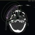
Figure 3.5 View of a treatment-planning system. A tandem and ring applicator with interstitial needles are placed under MR guidance. At the end of the implant procedure, both MR and CT scans are acquired and fused for planning as seen in the upper right panel. The tandem and ring applicator are well suited to the use of modeling to determine applicator configuration as shown in the upper right panel. The interstitial needles must be digitized and care must be taken to associate the appropriate needle with the correct treatment channel and ensure the needles are digitized to the appropriate depth. The model and needles are shown in the bottom right panel.
Evaluation
The criteria for evaluating a brachytherapy implant differ from external beam in some major respects. Brachytherapy plans, in addition to tumor and normal tissue coverage, need to be reviewed in multiple thin orthogonal planes.
Seeds, needles, catheters, and applicators need to be appropriately identified and be evaluated for position and orientation. Brachytherapy doses are typically prescribed as the minimum dose delivered to a well-defined target volume and have much greater heterogeneity than typically seen in external beam dose distributions (39–41). Targets may have very large dose gradients. Hot spots in excess of 200% can and do occur close to seed or dwell positions. Professional society guidelines or institutional standards should be followed in managing these hot spots. Large coherent hot spots may increase the likelihood of necrosis and complicate the treatment and recovery of the patient. However, well-managed hot spots may yield a tumor-kill advantage, provided the hot spot is controlled in size and corralled to an appropriate area within the tumor and is positioned away from normal tissues. Knowledge of the effect of brachytherapy fractionation and the radiobiologic implications is required to convert to normal dose regimen equivalences.
When evaluating the plan, the physicist must evaluate the plan on its robustness and reproducibility and ask the following and similar questions:
• Anatomy
– Is the anatomy likely to change over the course of treatment, for example, swelling or shrinkage?
– Will changes in normal tissue size and position alter the dosimetry adversely?
• Hardware
– How stable is the implant?
– Are the seeds likely to drift or bunch?
– Is a planar implant well secured?
– Can interstitial needles slip in a template prior to subsequent fraction delivery in HDR?
• Optimization
– Is the plan overoptimized? Is the plan over reliant on too few seed or dwell locations?
– What would the dosimetry be like if an overutilized region is misaligned or if a catheter becomes kinked and unusable?
• Verification
– Can the principal elements of the plan—dose, time, activity, source, and reference point positions—be extracted, recalculated, and verified? Such verifications will need a second calculation engine either commercial or in-house, or a direct measurement technique, preferably performed by a second qualified person.
Related posts:


Stay updated, free articles. Join our Telegram channel

Full access? Get Clinical Tree


